1
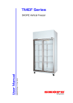
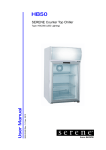
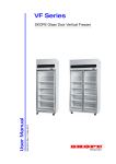
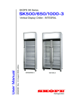
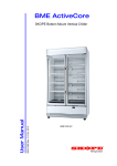
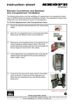
Display Series
SKF Range
PRN7691 Rev. 4.0 April 2008 edition
User Manual
SKOPE Top Mounted Vertical Freezers
ASSEMBLY INSTRUCTIONS
1.
Lift the SKOPE Cyclone ® Freezer unit onto the cabinet top. Steps or
platform about 1 metre high are suggested. NOTE: Cyclone ® unit
weights are: SKF650 = 57.5 kg, SKF1000 = 78.5 kg.
2.
Remove wooden packing from unit where applicable.
3.
Take care to avoid damaging sealing strips & cabinet supply flex.
4.
Fix unit to cabinet top by screwing the two fixing screws provided
firmly down. The unit should be flush with the back of the cabinet
when positioned correctly.
Check seal against cabinet top - ensure there are NO gaps!
5.
6.
Fit side panels onto cabinet by sliding the two slots under the screws
on the cabinet top. These screws should be raised approx. 1.5mm off
the cabinet top.
7.
Fit mains flex through the exit hole in the top of the sign back.
8.
Clip sign back into place, and connect ‘cabinet’ and ‘sign’ plugs into
power supply sockets, where applicable.
Fit the Microprocessor cable and four coloured cables into
processor, where applicable.
9.
10. Connect illuminated sign into sign power socket. Clip sign unit or
plain facia panel into place.
11. Proceed with installation as outlined in ‘Positioning of Machine’.
Mains Flex
Sign Back
Sign Side Panel
Sign Side Panel
Cyclone® unit
securing screw
and Clip
Cyclone® unit
securing screw
Compressor
Sign Securing Screws
Light and Sign
Power Sockets
Sign Unit or Plain Facia Panel
Microprocessor Display
Figure 1: Top view of Cabinet (SKF650 shown)
2
SKF Range
SKOPE Top Mounted Vertical Freezers
POSITIONING OF MACHINE
The mains flex exits below the rear panel behind the refrigeration unit. The
flex should be retrieved before the machine is positioned, when walls and
partitions may make access difficult.
When positioning the machine, a gap must be left between the top of the
sign panels and ceiling, of at least 200mm. Adequate ventilation must be
provided above the SKOPE Cyclone ® unit for efficient operation. The air
surrounding the unit must not exceed 40°C.
Avoid direct sunlight, warm draughts etc. When siting the machine
adequate allowance should be made for door opening. The doors have
internal torsion bars which are pre-tensioned at the factory and the
machine must be positioned on a level surface for the door/s to shut and
seal correctly and to prevent the condensate tray from overflowing.
The operation of this machine is controlled by a pre-programmed
Microprocessor Controller. For more detailed service information please
refer to the relevant SKOPE service manual.
VENTILATION
Adequate ventilation is essential. Freezer cabinet must have the Sign Back
or Duct Kit fitted. This ensures that fresh air is drawn through the
condenser. Failure to fit either of these components will void warranty.
Positioning the cabinet back closer than 100mm to wall will result in freezer
unit failure.
Ceiling
200mm min.
Airflow
Front of cabinet
100mm
Wall
Figure 2: Ventilation
SKF Range
SKOPE Top Mounted Vertical Freezers
3
OPERATION OF MACHINE
Plug in machine and check operation of refrigeration unit and lights.The
condenser fan runs continuously through out all operations of the machine.
(this may be verified by checking for air movement around the top right
hand side of the cabinet).
The compressor should switch off when cabinet internal air reaches the
preset “set point” temperature.
The evaporator fan/s which circulate the cabinet air will not operate until the
defrost thermostat bulb senses a temperature of -8°C. On initial start up the
fan should come on after a delay of approximately 4 minutes (verified by air
blowing out of the bottom duct and the green LED.
Defrost
The first defrost will occur in 6 hours. During a defrost cycle (indicated by
the green defrost LED (item 7) on the control panel) the compressor and
the evaporator fan will switch off. Four elements inside the evaporator box
will then melt away any ice build up.
The duration of a defrost cycle depends on the quantity of ice build up
(usually about 10 minutes). A maximum of 20 minutes is preset. Defrost
cycles are pre-programmed at 6 hour intervals.
During and after each defrost, the display will read the temperature
detected before the defrost cycle. The display will then show the return air
temperatures as the machine cycles during normal operation.
Defrosts should occur during off-peak periods to maximise the efficiency of
the machine. This can be achieved by switching the power off, then on
again, so that the subsequent 6 hourly cycle defrosts will not coincide with
peak periods.
Notes:
•
•
•
•
4
A power cut would reset the defrost cycles.
This machine has an over temperature cut-out inside the refrigeration
unit evaporator box. This is to safe guard the possibility of the defrost
elements remaining on under fault conditions (set at 55°C).
The lights which illuminate the top sign and cabinet interior are
permanently on, where applicable.
Ensure the door gasket/s form a good seal with the cabinet.
SKF Range
SKOPE Top Mounted Vertical Freezers
LOADING
Shelves may be positioned at different heights to suit various products.
Always ensure that the shelf clips are securely engaged in each of the shelf
support strips. Support strips are marked ‘+’ for easy location of shelf clips.
For even cooling and efficient operation, allow air space around packages
etc. Do not allow products to overhang the front of the shelf as this could
prevent the door from shutting or cause glass breakage. Leave an airspace
of at least 75mm (3") above packages etc. on the top shelf.
CLEANING
When necessary, wash both interior and exterior of cabinet with soapy
water. Exterior of cabinet may be waxed with automobile polish for extra
protection.
Caution:
The machine must be disconnected from the mains supply before cleaning
the condenser.
Important:
Condenser coil MUST be kept clean for efficient and reliable operation.
Clean with a brush and vacuum cleaner regularly.
Access to the condenser coil is gained over the top of the sign, or by
removing the sign. To remove the sign, undo the two screws which hold the
top of sign to the sign side panels. The sign unit can then be lifted vertically,
unplugged and removed.
SERVICE INSTRUCTIONS
Servicing should be carried out by an authorized Service Agent. Brief
instructions are located on top of the refrigeration unit.
SKF Range
SKOPE Top Mounted Vertical Freezers
5
CAREL ELECTRONIC CONTROLLER
Display and Key Functions
9
10
11
1
3
8
7
Figure 3: Controller Display
6
5
2 4
Silences alarm buzzer.
Allows entry to frequent parameters section, if pressed for 5 seconds.
Allows entry to configuration parameters section, if pressed
simultaneously with ‘SEL’ for 5 seconds.
1
Locks in new parameters, and exits parameter sections.
Activates reset procedure.
Displays setpoint in run mode.
Displays selected parameter in parameter mode.
2
Allows entry to configuration parameters section if pressed
simultaneously with ‘PRG’ for 5 seconds.
Adjustment locked out
3
Alters parameters in parameter mode.
Activates and deactivates continuous refrigeration mode with ‘def’ key.
Adjustment locked out
Activates manual defrost cycle.
4
Alters parameters in parameter mode.
Activates and deactivates continuous refrigeration mode with ‘aux’ key.
6
5
Decimal point indicator.
6
Unused.
7
Defrost cycle on indicator
8
Evaporator fan on indicator.
9
Continuous refrigeration mode on indicator (fast freeze).
10
Compressor on indicator.
11
Remote controller indicator.
SKF Range
SKOPE Top Mounted Vertical Freezers
CAREL ELECTRONIC CONTROLLER
Operation of Controller
The operation of this cabinet is controlled by a pre-programmed
microprocessor. The Microprocessor display indicates the temperature of
the cabinet ambient probe, except during a defrost where the temperature
of the cabinet probe is locked in, and during an alarm condition.
The display also has LED indicators showing the activation of the
compressor, the fan and the defrost. At alarm activation, the display
indicates the type of alarm signal; and an audible alarm sounds. The alarm
can be muted at the controller.
Controller Components
•
•
Component
Description
Microprocessor:
Located behind ventilated unit cover.
Controller Module:
Located in control box. Performs processor
switching.
Module Connector
Cable:
Flat black cable connecting module to
microprocessor.
Probes:
2 x NTC probes are used.
A controlling probe located on a receptacle in the evaporator box,
called a ‘Cabinet Ambient Probe’.
An evaporator probe located within the evaporator coil, referred to as a
‘Defrost Probe’.
SKF Range
SKOPE Top Mounted Vertical Freezers
7
CAREL ELECTRONIC CONTROLLER
Alarms and Signals
SIGNAL
DESCRIPTION
EO on
Indicates faulty ambient probe.
El blinking
Indicates faulty defrost probe.
IA blinking
Indicates unit has high pressure fault.
Note: At alarm initiation, check condenser radiator for blockage,
and clean if necessary. To reset alarm, cabinet must be
replugged into power supply.
LO blinking
Indicates low temperature alarm.
HI blinking
Indicates high temperature alarm.
EA, EB or EE blinking
Indicates data acquisition failure.
The controller requires re-programming.
Ed blinking
Indicates defrost timed out.
Note:
Alarm HI may activate during cabinets initial pull down cycle, after being
first powered up. Alarm may be muted; and will automatically reset when
cabinet passes alarm setpoint.
Changing Controller Settings
Access / Entry:
1. Press and hold PRG and SEL simultaneously for more than 5 seconds,
until 00 is displayed.
2. Press aux (up) until 22 is displayed.
3. Press SEL to confirm selection. The first parameter /C is displayed.
Turn Keypad On:
1. Follow Access / Entry above, until the first parameter /C is displayed.
2. Press def (down) two times, until H2 is displayed.
3. Press SEL to display the ‘value’ of the parameter.
4. Press aux (up) to increase or def (down) too decrease, until 01 is
displayed.
5. Press SEL to accept the ‘value’.
6. Press PRG to lock in new value and to exit program.
8
SKF Range
SKOPE Top Mounted Vertical Freezers
CAREL ELECTRONIC CONTROLLER
Setpoint
•
•
•
Factory setting:
-21°C
Maximum:
-18°C
Minimum:
-21°C
Press SEL key for 1 second and the ‘Setpoint’ will be displayed. On
releasing the key, the display will flash.
To alter the ‘Setpoint’, press aux (up) or def (down).
Press SEL to lock in the value and return to cabinet temperature.
Manual Defrost
Press def (down) key for more than 5 seconds to manually initiate a defrost.
Continuous Refrigeration
Press aux (up) and def (down) together, (down key first) to initiate a
‘Continuous Refrigeration’ mode. The compressor will run without
interruption to the parameter ‘cc’ (6 hours: SKOPE programme). Its
purpose is to achieve a fast product pull-down.
Display Function
During run mode, the display shows the value measured by the ‘Cabinet
Ambient Probe’. In alarm status, the display indicates the relative alarm
code.
Buzzer Off
Press mute key to silence the buzzer. The alarm display remains while the
alarm condition exists.
Parameters
Warning:
•
•
•
The following parameters (Table 1: pp.10,11) are set exclusively for
the SKOPE freezer program, with its dedicated CAREL controller.
Any alteration from this program may adversely effect the operation of
the freezer.
For full specifications, a detailed CAREL controller manual is available.
SKF Range
SKOPE Top Mounted Vertical Freezers
9
CAREL ELECTRONIC CONTROLLER
Parameters
SKOPE Parameters for CAREL Controller IR32POLBRO
SETPOINT: -21°C (cycling -21°C to -18°C)
SKOPE Settings
PA
22
Type
Min
Max
Def
C
00
199
22
PARAMETER
n.a.
0
1
0
Type of probe used (NTC or PTC). Available after ‘Reset
Procedure’
Password
PROBE PARAMETERS
/0
0
NTC probe
/C
2.0
2°C
F
-20
20
0
Calibration offset for cabinet temperature display
/2
04
-
C
1
15
4
Probe reading stability (lower the number, faster the
response)
/3
08
-
C
1
15
8
Probe reading speed (lower the number, slower the
response)
/4
00
probe
C
0
100
0
Designation as controlling probe
/5
00
°C
C
0
1
0
Units of temperature measurement
/6
00
Yes
C
0
1
0
Decimal point display
rd
3.0
3°C
F
0.1
20
2
r1
-26
-26°C
C
-40
r2
-40
Minimum allowable setpoint
r2
-16
-16°C
C
r1
199
90
Maximum allowable setpoint
r3
01
Yes
C
0
1
0
Enabling of ED alarm (defrost interrupted because maximum
duration has been reached, parameter dP) 0=No, 1=Yes
r4
3.0
3
C
0
20
3
Not used. Must be 3
r5
01
Yes
C
0
1
0
Enabling of minimum / maximum temperature monitoring
rt
-
-
F
0
199
-
Actual interval in maximum / minimum temperature reading
rH
-
-
F
-50
+90
-
Maximum temperature reading in the ‘rt’ interval
rL
-
-
F
-50
+90
-
Minimum temperature reading in the ‘rt’ interval
c0
01
1 minute
C
0
15
0
Compressor and evaporator fan start delay at power on
c1
03
3 minutes
C
0
15
0
Minimum time between compressor starts
c2
03
3 minutes
C
0
15
0
Minimum compressor OFF time
c3
00
0
C
0
15
0
Minimum compressor ON time
c4
99
99 minutes
C
0
100
0
Compressor backup for ‘Ambient’ probe failure (On for c4, off
for 15 min)
CYCLE PARAMETERS
Refrigeration differential
COMPRESSOR PARAMETERS
cc
04
4 hours
C
0
15
4
Duration of ‘Continuous Refrigeration Mode’
c6
02
2 hours
C
0
15
2
Duration of alarm override after ‘Continuous Refrigeration
Mode’
d0
00
Electric
C
0
1
0
Type of defrost
dl
06
6 hours
F
0
199
8
Time interval between defrosts
dt
12
12°C
F
-40
199
4
Defrost termination temperature
dP
22
22 minutes
F
1
199
30
Maximum defrost time
d4
00
No
C
0
1
0
Defrost at cabinet plug in
d5
00
No
C
0
199
0
Defrost delay at cabinet plug in
d6
01
Yes
C
0
1
1
Lock in temperature display during defrost
dd
03
3 minutes
F
0
15
2
Defrost drip time, before compressor and evaporator fan
start
d8
01
1 hour
F
0
15
1
Continuation of d6 at defrost end (until setpoint or d8
elapses)
d9
00
No
C
0
1
0
Compressor protection times observed at defrost (c1, c2, c3)
d/
-
-
F
n.a
n.a
n.a
dC
00
hrs / mins
C
0
1
0
DEFROST PARAMETERS
Evaporator temperature (via defrost probe) is displayed
Time basis for parameter ‘dl’ and ‘dp’
Table 1: CAREL Controller Parameters - continued on next page
10
SKF Range
SKOPE Top Mounted Vertical Freezers
CAREL ELECTRONIC CONTROLLER
Parameters
SKOPE Parameters for CAREL Controller IR32POLBRO
SETPOINT: -21°C (cycling -21°C to -18°C)
SKOPE Settings
Type
Min
Max
Def
PARAMETER
ALARM PARAMETERS
AO
1.0
1.0°C
C
0.1
20
0.2
Alarm and fan differential
AL
10
-32°C /-31°C
F
0
199
10
Low temp alarm (On=Setpoint -AL-A0) (Off=Setpoint -AL)
AH
09
-11°C /-12°C
F
0
199
10
High temp alarm (On=Setpoint +AH+A0) (Off=Setpoint
+AH)
Ad
60
60 minutes
C
0
199
120
Alarm delay time
A4
01
On
C
0
5
0
Immediate external alarm i.e. High pressure switch trip*
A5
00
-
C
0
5
0
Not used. must be 0
A6
99
99 minutes
C
0
100
0
Compressor run lock time due to A4 function.
Compressor will still cycle with HP switch
A7
00
-
C
0
199
0
Not used. must be 0
F0
02
On
C
0
1
0
Evaporator fan control type (controlled by Evaporator
Defrost Probe). Must be 2
F1
14.0
-8°C /-7°C
F
0
20
5
Evaporator fan start temperature (On=Setpoint +F1 -A0)
(Off=Setpoint +F1)
F2
00
No
C
0
1
1
Evaporator fan off while compressor is off
F3
01
Yes
C
0
1
1
Evaporator fan off during defrost
Fd
01
1 minute
F
0
15
1
Evaporator Fan delay after defrost
H0
00
-
C
0
15
0
Serial address
H1
00
-
C
0
1
1
Not used. Must be 0
H2
00
No
C
0
3
1
Enable keypad and remote control (must be ‘01’ to
enable)
H3
00
00
C
0
199
0
Password for remote control
FAN PARAMETERS
OTHER SELECTIONS
* High Pressure trip is maintained as alarm status by latching relay. To
reset, the freezer must be unplugged and then replugged into the power
supply.
Parameter Modification (if keypad is enabled)
1. Press aux (up) or def (down) to show the code of the parameter that
has to be changed.
2. Press SEL to display the selected parameter value.
3. Press aux (up) or def (down) to increase or decrease the value.
4. Press SEL to temporarily confirm the new value, and display its code.
5. Repeat above procedures to alter further parameters.
Press PRG to lock in the new parameters and exit parameter modification
procedure.
SKF Range
SKOPE Top Mounted Vertical Freezers
11
CONTACT ADDRESSES
New Zealand
SKOPE INDUSTRIES LIMITED
PO Box 1091, Christchurch
New Zealand
Freephone: 0800 947 5673
Fax: (03) 983 3896
Email: [email protected]
Website: www.skope.co.nz
Australia
SKOPE AUSTRALIA PTY LTD
A.C.N. 000 384 270
PO Box 7543, Baulkham Hills
NSW 2153, Australia
Freephone: 1800 121 535
Freefax: 1800 121 533
Email: [email protected]
Website: www.skope.com.au
SKF Range
User Manual
PRN7691
Rev. 4.0 April 2008 edition
Published by
SKOPE Industries Limited,
Christchurch, New Zealand.
Copyright © 2002
SKOPE Industries Limited.
All rights reserved.
SKOPE is the registered trademark of
SKOPE Industries Limited.
SKOPE Industries Limited reserve the
right to alter specifications without notice.
12
SKF Range
SKOPE Top Mounted Vertical Freezers