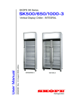
1
BME ActiveCore MAN11080 Rev. 3.2 Oct. 2015 User Manual SKOPE Bottom Mount Vertical Chiller BME1200-AC SKOPE Warranty Protection Register now for peace of mind It’s quick and simple. Take a few minutes to register your SKOPE product and enjoy more efficient support plus other warranty benefits. When registering, make sure you have your cabinet serial number at hand. To register online: Visit our website at www.skope.com/warrantyprotection then complete and submit the online registration form. Or freephone: 1800 121 535 (Australia) 0800 947 5673 (New Zealand) SKOPE 1-year Extended Warranty Extend your Warranty Protection by 1 year during registration. Please check you have not already organised an extended warranty through your dealer at time of purchase. For pricing information on an extended warranty visit www.skope.com/warrantyprotection Service & Support We know you will get years of satisfaction from your new SKOPE product when you follow a few simple preventative maintenance guidelines. Helpful information is available on our website www.skope.com/serviceandsupport Thank you for purchasing a SKOPE refrigeration product. CONTENTS 1 Installation Safety First . . . . . . . . . . . . . . . . . . . . . . . . . . . . . . . . . . . . . . . . . . . 4 Positioning the Cabinet . . . . . . . . . . . . . . . . . . . . . . . . . . . . . . . . . . . . 5 Climate Class . . . . . . . . . . . . . . . . . . . . . . . . . . . . . . . . . . . . . . . . . 5 Chiller Location . . . . . . . . . . . . . . . . . . . . . . . . . . . . . . . . . . . . . . . 5 Power Cord . . . . . . . . . . . . . . . . . . . . . . . . . . . . . . . . . . . . . . . . . . 5 Ventilation . . . . . . . . . . . . . . . . . . . . . . . . . . . . . . . . . . . . . . . . . . . . 5 Before Operating. . . . . . . . . . . . . . . . . . . . . . . . . . . . . . . . . . . . . . . 5 Door Handles . . . . . . . . . . . . . . . . . . . . . . . . . . . . . . . . . . . . . . . . . . . 6 Fitting Door Handles . . . . . . . . . . . . . . . . . . . . . . . . . . . . . . . . . . . 6 Removing Door Handles . . . . . . . . . . . . . . . . . . . . . . . . . . . . . . . . 7 Shelves . . . . . . . . . . . . . . . . . . . . . . . . . . . . . . . . . . . . . . . . . . . . . . . . 8 Shelf Clips . . . . . . . . . . . . . . . . . . . . . . . . . . . . . . . . . . . . . . . . . . . 8 Repositioning Shelves . . . . . . . . . . . . . . . . . . . . . . . . . . . . . . . . . . 9 2 Operation Automatic Start-Up . . . . . . . . . . . . . . . . . . . . . . . . . . . . . . . . . . . . . . 10 Lighting . . . . . . . . . . . . . . . . . . . . . . . . . . . . . . . . . . . . . . . . . . . . . . . 10 LED Tube Side Light . . . . . . . . . . . . . . . . . . . . . . . . . . . . . . . . . . 10 LED Modular Shelf and Side Lighting . . . . . . . . . . . . . . . . . . . . . 10 Sign Light . . . . . . . . . . . . . . . . . . . . . . . . . . . . . . . . . . . . . . . . . . . 10 Loading Product . . . . . . . . . . . . . . . . . . . . . . . . . . . . . . . . . . . . . . . . 11 Electronic Controller . . . . . . . . . . . . . . . . . . . . . . . . . . . . . . . . . . . . . 12 Introduction . . . . . . . . . . . . . . . . . . . . . . . . . . . . . . . . . . . . . . . . . 12 Faceplate . . . . . . . . . . . . . . . . . . . . . . . . . . . . . . . . . . . . . . . . . . . 12 Normal and Energy Saving Modes . . . . . . . . . . . . . . . . . . . . . . . 13 Lights . . . . . . . . . . . . . . . . . . . . . . . . . . . . . . . . . . . . . . . . . . . . . . 13 Door Switch . . . . . . . . . . . . . . . . . . . . . . . . . . . . . . . . . . . . . . . . . 14 Temperature Setpoint . . . . . . . . . . . . . . . . . . . . . . . . . . . . . . . . . 14 Messages and Alarms . . . . . . . . . . . . . . . . . . . . . . . . . . . . . . . . . 14 3 Servicing Isolating Electrics . . . . . . . . . . . . . . . . . . . . . . . . . . . . . . . . . . . . . . . 15 Cleaning . . . . . . . . . . . . . . . . . . . . . . . . . . . . . . . . . . . . . . . . . . . . . . 16 Cabinet . . . . . . . . . . . . . . . . . . . . . . . . . . . . . . . . . . . . . . . . . . . . . 16 Condenser Coil & Filter . . . . . . . . . . . . . . . . . . . . . . . . . . . . . . . . 16 Lighting . . . . . . . . . . . . . . . . . . . . . . . . . . . . . . . . . . . . . . . . . . . . . . . 18 LED Tube Side Lighting . . . . . . . . . . . . . . . . . . . . . . . . . . . . . . . . 18 LED Modular Shelf and Side Lighting . . . . . . . . . . . . . . . . . . . . . 18 Sign Light . . . . . . . . . . . . . . . . . . . . . . . . . . . . . . . . . . . . . . . . . . . 18 Troubleshooting. . . . . . . . . . . . . . . . . . . . . . . . . . . . . . . . . . . . . . . . . 19 SKOPE BME ActiveCore User Manual iii SKOPE BME ActiveCore 1 Installation Safety First Always observe safety precautions when using any electrical appliance. Read these instructions carefully and retain them for future reference. When the appliance is used by or near young children or infirm persons, close supervision is necessary, especially to ensure children do not play with it. Do not use this appliance for other than its intended use. Do not cover the grilles or block the entry or exhaust of airflow by placing objects up against the refrigeration unit. Do not probe any opening. Only use this appliance with the voltage specified on the cabinet rating label affixed to the refrigeration unit. Ensure the appliance has adequate ventilation as this is essential to economical, high performance. Be careful not to touch moving parts and hot surfaces. For your own safety and that of others, ensure that all electrical work is done by authorised personnel. If the power supply flexible cord becomes damaged, it must be replaced by an authorised service agent or similarly qualified person in order to avoid a hazard. Ensure all necessary safety precautions are observed during installation or removal of the refrigeration unit. The appliance is not designed to be stable while in motion. Use extreme caution when moving or transporting it. Do not store explosive substances such as aerosol cans with a flammable propellant in this appliance. Please contact SKOPE Customer Services for advice regarding disposal of this appliance. CAUTION Never overload the power supply, which could damage the chiller and product. See the rating label inside the cabinet for the safe power supply and current draw. WARNING Always disconnect the chiller from the mains power supply before cleaning or maintenance. 4 Installation User Manual SKOPE BME ActiveCore Positioning the Cabinet Climate Class The chiller is designed to operate within a climate class 5 environment (40°C @ 40% RH). We recommend that you put the chiller in the coolest place possible because it will use less power and last longer. Chiller The location of the chiller may be the single most important decision that will Location extend its life and ensure economical, high performance. Allow adequate space for the door/s to open and close properly. Self-closing doors have internal torsion bars pretensioned at the factory. Ensure the cabinet sits on a level surface so that the door shuts and correctly seals, and that the doors are unobstructed. Level footing also prevents the condensate tray from overflowing. Power Cord The chiller has a flexible power cord fitted with a 3-pin plug, which exits the rear of the cabinet at floor level. Locate the power cord before the cabinet is moved into position so that it is not trapped behind the cabinet. Ventilation Ensure there is always at least a 50mm gap around the back, top and underside of the cabinet. Keep the ventilation slots in the lower front panel clear at all times. Never store cardboard cartons or other objects in front of the chiller. CAUTION To prevent over heating and conserve energy, ensure air flows freely all around the chiller - including front, back, top and underside (minimum 50mm gap). Before Ensure both rear spacers are fully extended outwards and locked into place. Operating This will provide the necessary air gap at the rear of the cabinet for correct operation. Back of chiller Rear spacer Installation User Manual 5 SKOPE BME ActiveCore Door Handles Fitting Door For transit purposes the door handles may be packed separately inside the Handles cabinet. If the door handles are packed separately, follow the steps below to fit them to the door/s. To fit a door handle 1. Remove the handle/s from inside the cabinet by carefully cutting the cable ties securing the handle, and remove the packaging. 2. A metal spring clip is fitted inside the handle mounts at each end of the handle. Rotate the handle so that the spring clips point up. Spring clip (pointing up) Handle mount Bracket 3. Locate both of the handle mounts onto the brackets on the front of the door, and push the handle down onto the brackets until an audible click is heard and the handle locks into place. Front of door Handle Bracket If the handle does not lock into place, check the orientation of the handle and try again. If only one end of the handle locks into place, follow the steps over the page to remove the door handle, and refit ensuring both of the handle mounts are located onto the brackets before pushing the handle down and locking into place. 6 Installation User Manual SKOPE BME ActiveCore Removing The door handles can be removed for transporting and moving the cabinet Door Handles through doorways. To remove a door handle 1. Open the door, and peel back the door gasket from behind the handle mounts on the inside of the door frame. 2. Unscrew the handle mounts through the holes on the inside of the door frame, and remove the handle. 3. Remove the bracket/s from the handle mount by pressing the bracket in and down until it unclips from the handle mount. 4. Fit and screw the bracket/s back onto the door. Ensure the catches are pointing up as pictured. Handle Handle mount Bracket Catch Bracket Catch 5. Refit the door gasket by clipping it back into place on the inside of the door frame. If the gasket is out of shape after refitting it, a hair drier can be used to heat and reshape it. Installation User Manual 7 SKOPE BME ActiveCore Shelves The chiller is fitted with wire shelves, which may be positioned at different heights to suit various products, and solid bottom shelf/ves. Solid bottom shelves are held in place by brackets attached to the floor of the chiller. It is important that solid bottom shelf/ves are always in place as they direct the interior air circulation. IMPORTANT For correct chiller operation, the bottom shelf/ves must always be in place at the bottom of the chiller. Interior shelf lit cabinets incorporate cabinet interior lights on the front of each shelf (see “LED Modular Shelf and Side Lighting” on page 10). Shelf Clips Each wire shelf is held in place with four shelf clips, which engage in the shelf support strips and slide up and down to the desired shelf position. The support strips are numbered for easy location of shelf clips. View the numbers in the bottom LH corner of the shelf clip. To fit a shelf clip 1. The shelf clip twists onto the shelf support strip. Position the shelf clip with the flat side up against the shelf support strip and the two prongs pointing up. Twist the top of the clip anticlockwise onto the shelf support strip until it locks in place. Prongs Shelf clip Shelf support strip To slide a shelf clip up and down 1. Pull the shelf clip tab up and slide the shelf clip up or down as required. Once in position, ensure the shelf clip is locked into place. Shelf clip Tab To remove a shelf clip 1. Pull the shelf clip tab up and twist the top of the clip clockwise off the shelf support strip. 8 Installation User Manual SKOPE BME ActiveCore Repositioning When repositioning standard shelves, unload and remove the shelf, Shelves establish the desired position and slide the shelf clip in each of the shelf support strips to the desired position (see “To slide a shelf clip up and down” on page 8). Sit the shelves on the shelf clips. When repositioning shelves fitted with shelf lights, the height is adjusted as per normal with the shelf clips. The shelves can be repositioned as far as the shelf light cable reasonably allows via the fixed cut out in the side channel cover (see procedure below). To reposition shelves fitted with lights 1. Isolate the chiller from the power supply (see “Isolating Electrics” on page 15). 2. Remove product from the shelf required to be moved, and from the shelf immediately above it. 3. Establish the desired shelf position. 4. Support the weight of the shelf and lift it up off the shelf clips. Be careful not to damage the connected shelf light cables running through the front shelf clips. 5. Slide the shelf clip in each of the shelf support strips to the desired position (see “To slide a shelf clip up and down” on page 8). The shelves can be repositioned as far as the shelf light cable reasonably allows. 6. After the shelves have been securely positioned, connect cabinet to the power supply and check for correct operation. 7. Reload the shelves with product. Installation User Manual 9 SKOPE BME ActiveCore 2 Operation Automatic Start-Up After the cabinet has been positioned in a suitable place, plug it in and check the following activity. Item Activity Electronic Controller An electronic controller runs the chiller and is visible behind the front panel. The display panel first flashes start-up messages before stabilising on the cabinet temperature. Lighting The lights that illuminate the sign and cabinet interior will come on approximately five seconds after the chiller is turned on. The compressor and condenser fan will start approximately one minute after the chiller is turned on. Compressor and Condenser Fan Evaporator Fan To verify, listen for the compressor and check that the COMPRESSOR light is lit on the electronic controller. The compressor and condenser fan will turn off when the product temperature reaches around +2°C, and on again when it reaches about +4°C (SKOPE BME ActiveCore default settings). The evaporator fan starts approximately three seconds after the compressor and condenser fan. To verify, check that the FAN light is lit on the electronic controller. Lighting The cabinet interior lighting will consist of either LED tube side lights, or LED modular shelf and side lighting. The cabinet may also be fitted with a top sign assembly which is lit by an LED tube. The cabinet lighting will automatically switch on and off depending on chiller usage. The lights can also be manually switched on and off using the light button on the electronic controller faceplate (see page 12). LED Tube Side Cabinets with LED tube side lights are fitted with LED tube/s which can be Light replaced without moving shelves or product (see page 18 for replacement instructions). LED Modular Cabinets with LED modular shelf and side lighting are lit by shelf lights Shelf and Side mounted on the front of the shelves (two lights per shelf), and LED side Lighting lights. LED modular light components are all non-serviceable items and must not be tampered with in any way. If a component is suspected of being faulty, a service call should be arranged so that a replacement component can be fitted. Sign Light Cabinets with a lit sign are fitted with an LED tube, located inside the top sign assembly. In the event of sign light failure, a service call should be arranged so that a replacement LED tube can be fitted. 10 Operation User Manual SKOPE BME ActiveCore Loading Product Let the chiller run 30 minutes before loading it with product the first time. When loading the shelves with product: Allow adequate air space around each item to ensure even cooling and efficient operation of the chiller. Do not exceed a maximum load of 20kg per shelf. Remove some product if the shelves are flexing. Do not let anything overhang the shelves because this might stop the doors from shutting or even break something. For security, there is a lock bracket above the door where you can attach a padlock and secure the door. Operation User Manual 11 SKOPE BME ActiveCore Electronic Controller Introduction The chiller is fitted with a Carel S4 electronic controller which is visible through a cutout in the cabinet front panel. The electronic controller is preprogrammed and requires no initial setup or additional programming. SKOPE does not recommend that the settings be changed unless it is absolutely necessary. CAUTION The electronic controller must only be adjusted by an authorised service agent. To achieve energy efficient operation, the electronic controller uses temperature probes and door switches to monitor chiller usage and switch the chiller between ‘Normal’ and ‘Energy Saving’ modes, control and display the chiller temperature, collect data, signal temperature alarms and force a defrost cycle when required. Faceplate Because the electronic controller plays such an important role, it’s helpful to know the parts of the faceplate you may use. 2 6 8 1 ES 7 5 3 4 No. 12 Item Description 1 Digital display of cabinet temperature or messages. The temperature is what the sensor inside the chiller detects, and not necessarily the product temperature. However, they may be very close depending on how the controller is set to sense temperature. 2 Energy Save (up): Button. Press to view the current chiller mode. ‘ECO’ = Energy Saving and ‘nor’ = Normal. Press and hold for 3 seconds to switch the chiller between ‘Energy Save’ and ‘Normal’ mode. ES 3 Set (mute): Button. Press to mute the alarm. Press and hold to access parameters. 4 Light (down): Button. Press and hold to switch the cabinet lights on and off. 5 Defrost: Indicator. ON when the defrost is activated. Flashes when the activation of the defrost is temporarily delayed due to procedures in progress. 6 Compressor: Indicator. ON when the compressor and condenser fan starts. Flashes when activation of the compressor is temporarily delayed. 7 Fan: Indicator. ON when the internal cabinet fans are activated. Flashes when activation of the fans is temporarily delayed. 8 Alarm: Indicator. ON when alarm is signalled. Operation User Manual SKOPE BME ActiveCore Normal and The electronic controller is programmed to run the chiller in ‘Normal’ mode Energy Saving or ‘Energy Saving’ mode. Modes When plugged in, the chiller will run in ‘Normal’ mode. If the front door/s are not opened for a specified time period (default setting is three hours), the electronic controller will switch the chiller from ‘Normal’ mode to ‘Energy Saving’ mode and the cabinet lights will turn off. The electronic controller will switch the chiller back into ‘Normal’ mode when a door is opened, or after a specified time period (default setting is nine hours) in ‘Energy Saving’ mode. To manually switch the chiller between ‘Normal’ and ‘Energy Saving’ modes, press and hold the Energy Save (up) button on the electronic controller faceplate. To change the default times for automatic switching between ‘Normal’ mode and ‘Energy Saving’ mode, follow the procedures below. To change the time between ‘Normal’ and ‘Energy Saving’ modes 1. Press and hold the set button for 3 seconds until PS is shown on the display, indicating entry into the controller settings menu. 2. Press the down button to scroll the menu until r6 is shown on the display. The r6 value is the time (in hours) without the door being opened. When this time is reached (during store closing hours or quiet periods) the electronic controller will switch the chiller from ‘Normal’ mode to ‘Energy Saving’ mode. The r6 value must be ≥1 hour. IMPORTANT Do not set r6 to 0. 3. Press the set button. The current r6 value (in hours) is shown on the display. 4. Press the up or down button to increase or decease the value (in hourly increments). 5. Press the set button to temporarily save the new r6 value. 6. Press the down button to scroll the menu until r7 is shown on the display. The r7 value is the maximum time (in hours) that the chiller will stay in ‘Energy Saving’ mode. When this time is reached the electronic controller will switch the chiller from ‘Energy Saving’ mode to ‘Normal’ mode. 7. Press the set button. The current r7 value (in hours) is shown on the display. 8. Press the up or down button to increase or decease the value (in hourly increments). 9. Press the set button to temporarily save the new r7 value. 10. Press and hold the set button for 3 seconds to permanently save the new values and exit the controller settings menu. Lights When in ‘Normal’ mode the cabinet lights are on. When in ‘Energy Saving’ mode the cabinet lights are off. Press the Light button on the electronic controller faceplate to manually switch the cabinet lights on and off. Operation User Manual 13 SKOPE BME ActiveCore Door Switch Each door is fitted with a door switch which tells the electronic controller when the door is opened and closed. If the door is opened for over two minutes an alarm will sound. Press the set (mute) button on the electronic controller to mute the alarm. Temperature The chiller temperature setpoint is factory set at 2.5°C for storage of Setpoint perishable products (all shelves maintain temperatures below 5°C). The cabinet setpoint can be adjusted between 1°C and 15°C for other specialist applications if required (see below). SKOPE do not recommend that the setpoint be changed unless it is absolutely necessary, and then only by small increments at a time. To view and adjust the temperature setpoint 1. Press and hold the set button for 3 seconds until PS is shown on the display, indicating entry into the controller settings menu. 2. Press the up or down button to scroll the menu until St is shown on the display. 3. Press the set button. The current setpoint value is shown on the display. 4. Press the up or down button to increase or decease the setpoint value to the required temperature. 5. Press the set button to temporarily save the setpoint value. 6. Press and hold the set button for 3 seconds to permanently save the setpoint value and exit the controller settings menu. Messages and The following table explains messages and alarms that the electronic Alarms controller displays. Display Description Message: The chiller is in ‘Normal’ mode and the electronic controller displays the chiller temperature. Message: The chiller is in ‘Energy Saving’ mode. When in Energy Saving mode the temperature inside the chiller is moderated and the cabinet lights turn off. The lights can be switched on and off by pressing the light button on the controller faceplate, and the chiller can be switched into ‘normal’ mode by pressing the Energy Saving button on the electronic controller faceplate. Alarm: The front door has remained open for over two minutes. An alarm sounds, and the compressor and evaporator fan turn off. Alarm: Probe failure. A temperature probe has failed and an alarm sounds. Contact a service agent. Alarm: There is a refrigeration system error and the controller turns the chiller off to avoid damage. An alarm sounds, and the compressor and evaporator fan turn off. Contact a service agent. 14 Operation User Manual SKOPE BME ActiveCore 3 Servicing Isolating Electrics The chiller MUST be isolated from the power supply before attempting any maintenance. Either unplug the cabinet from the wall or use the isolation switch to turn off electrics to the cabinet and refrigeration unit. The isolation switch is located behind the cabinet front kick panel, on the right-hand side of the refrigeration unit compartment. To isolate the electrics 1. Open the door and undo the fixing screws from the top of the front kick panel. Pull the kick panel out to remove. Note: The electronic controller is attached to the front kick panel. Take care of cables when removing the front kick panel. Door (open) Isolation switch Electronic controller Front kick panel (removed) 2. Switch off (O) the power at the isolation switch, located on the right-hand side of the refrigeration unit compartment. 3. Once the maintenance work has been completed, remember to turn the isolation switch back on (I) before refitting the front kick panel. Servicing User Manual 15 SKOPE BME ActiveCore Cleaning Cabinet Periodically wipe the inside and outside of the cabinet with a damp cloth, taking care to keep moisture away from electrical parts. As with any maintenance, ensure the chiller is isolated from the power supply before cleaning. Condenser To ensure trouble-free performance, we strongly urge monthly cleaning with Coil & Filter a soft brush to remove dust and fluff. A more thorough cleaning is required by qualified service personnel every six months. The condenser and filter must be kept clean for efficient and reliable operation. The condenser coil is located on the front of the refrigeration unit. The optional filter is located on the front panel in front of the condenser coil. The optional filter is disposable and should be replaced when it shows signs of wear. Do not apply hot water, blow dry or place in dishwasher. WARNING Isolate the chiller from the power supply before cleaning the condenser coil (see page 15). To clean the optional filter 1. Rotate the grille at the bottom of the front kick panel out to gain access to the filter. Front kick panel grille Front kick panel grille (rotated out) 2. To remove the filter, use the finger loops to pull the filter up and detach from the front kick panel. Finger loop 3. Clean the filter with a vacuum cleaner, wash with cold water and shake excess water off before refitting. Do not apply hot water, blow dry or place in dishwasher. If necessary, discard and refit new air filter. 4. To refit the filter, insert it up into the front kick panel vent with the finger loops facing out. Then clip the into the slots on the bottom face of the front kick panel vent. 16 Servicing User Manual SKOPE BME ActiveCore To clean the condenser coil 1. Remove the front panel and isolate the chiller from the power supply (see “Isolating Electrics” on page 15). 2. Brush the condenser coil with a soft brush to remove any dust and fluff. Condenser coil 3. Turn the isolation switch back on (I) and refit the front panel. Servicing User Manual 17 SKOPE BME ActiveCore Lighting This chiller is designed for use with LED tube lights and is not compatible with fluorescent tubes. IMPORTANT DO NOT use fluorescent tubes. LED Tube Side LED tube side lit cabinets are lit by one or two T8 LED tube side lights, which Lighting can be replaced without moving shelves or product. See the table below for light tube specifications. Interior light tube specifications Item Description Interior light Eco-Point 20 Watt T8 LED tube (Ø26mm x1350mm) To replace an LED tube side light 1. Remove the front kick panel and isolate the chiller from the power supply (see page 15). 2. Remove the diffuser by squeezing it until it is released from the aluminium housing, and then push the diffuser out of the way. 3. Rotate the LED tube until the pins on the ends of the tube align with the slots, then slide it out. 4. Fit a new LED tube. Ensure the LED tube is fitted with the ‘Power’ end at the top (usually marked ‘POWER’ or similar). Note: If present, the pointer at each end of the tube should be set to the “0” position. Diffuser LED Tube Lamp holder Pins LED tube 5. Refit the diffuser by slipping the back section into the housing, then squeezing and snapping the front section of the diffuser into place as you work down the length of the light. LED Modular Cabinets with LED modular shelf and side lighting are lit by LED shelf lights Shelf and Side mounted on the front of the shelves (two lights per shelf), and LED side Lighting lights. LED modular light components are all non-serviceable items and must not be tampered with in any way. If a component is suspected of being faulty, a service call should be arranged so that a replacement component can be fitted. Sign Light BME600-AC and BME1200-AC chillers are fitted with a lit sign. In the event of sign light failure, a service call should be arranged so that a replacement LED tube can be fitted. 18 Servicing User Manual SKOPE BME ActiveCore Troubleshooting For questions about the electronic controller, see page 12. For problems with the cabinet and refrigeration unit, use the following table. Problem Possible Cause Suggestions • Cabinet not operating. • Loss of power supply. • Check mains power supply. • Isolating switch turned • Check isolating switch is turned on (I) (see page 15). off. • Controller alarm. • Refer to “Messages and Alarms” on page 14 • No controller display. • Loss of power supply. • Check mains power supply. • Isolating switch turned • Check isolating switch is turned on (I) (see page 15). off. • Light not on. • Electronic controller • Switch the light on while keeping the chiller in night displays ECO mode by pressing the light button on the electronic indicating the chiller is controller faceplate. in ‘Energy Saving’ • Change the chiller into ‘normal’ mode by pressing and mode. holding the Energy Saving button on the electronic controller faceplate, or open the door. • Lights switched off. • Switch light on by pressing the light button on the electronic controller faceplate. • Failed LED tube. • Replace LED tube (see page 17). • Failed LED shelf light. • Contact an authorised service agent to replace it. • Blown cabinet fuse. • Contact an authorised service agent to replace it. • Power consumption is • unit operating too hot. • Clean or replace the condenser filter (see page 16). higher than expected. • Clean the condenser (see page 16). • Ensure the cabinet is in a cool spot (see page 5). • Ensure the cabinet has good ventilation around the refrigeration unit (see page 5). • Product is too warm. • Cabinet doors are opened excessively. • Ensure doors are closed more often. • Restricted airflow to cabinet. • Ensure product is not blocking airflow slots. • Ensure there is space around individual product pieces. • Warm cabinet • Blocked condenser. temperatures. • Compressor operating • Poor ventilation for long periods (more around refrigeration than 1 hour). unit. Servicing User Manual • Clean or replace the condenser filter (see page 16). • Clean the condenser (see page 16). • Ensure the cabinet has good ventilation around the refrigeration unit (see page 5). 19 SKOPE Contacts SKOPE Industries Limited NEW ZEALAND CONTACT Head Office PO Box 1091, Christchurch New Zealand Freephone: 0800 947 5673 Fax: (03) 983 3896 E-mail: [email protected] Website: www.skope.co.nz AUSTRALIAN CONTACT A.B.N. 73 374 418 306 PO Box 7543, Baulkham Hills B.C. NSW 2153, Australia Freephone: 1800 121 535 Fax: 1800 121 533 E-mail: [email protected] Website: www.skope.com.au Trademark Infringement The SKOPE trademark on this product is infringed if the owner, for the time being, does any of the following: • Applies the trade mark to the product after their state, condition, get-up or packaging has been altered in any manner • Alters, removes (including part removal) or obliterates (including part obliteration) the trade mark on the product • Applies any other trade mark to the product • Adds to the product any written material that is likely to damage the reputation of the trade mark Notice of the above contractual obligations passes to: • Successors or assignees of the buyer • Future owners of the product BME ActiveCore SKOPE Bottom Mount Vertical Chiller User Manual MAN11080 Rev. 3.2 Oct. 2015 © 2015 SKOPE Industries Ltd. All rights reserved. ® SKOPE and the SKOPE logo are registered trade marks of SKOPE Industries Ltd. ActiveCore and the ActiveCore logo are trade marks of SKOPE Industries Ltd.