1
3
4
5
6
7
BIT 4
BIT 3
BIT 2
BIT 1
8
9
BIT 0
LSB
2
BIT 5
Transmitter
Data
Output
1
BIT 6
SMBCLK
From
Master
BIT 7
MSB
System Management Bus (SMBus) Specification Version 3.0
Receiver
Data
Output
S
NACK
START
Condition
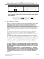
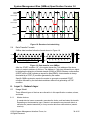
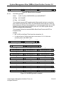
NACK: SMBDAT Is High During
The Ninth Clock Pulse
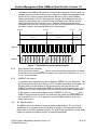
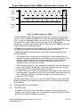
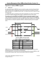
Figure 14. NACK signaling on SMBus
The acknowledge-related clock pulse is generated by the master. The transmitter,
master or slave, releases the SMBDAT line (HIGH) during the acknowledge clock
cycle. In order to acknowledge a byte, the receiver must pull the SMBDAT line LOW
during the HIGH period of the clock pulse according to the SMBus timing
specifications. A receiver that wishes to NACK a byte must let the SMBDAT line remain
HIGH during the acknowledge clock pulse.
A SMBus device must always acknowledge (ACK) its own address. SMBus uses
this signaling to detect the presence of detachable devices on the bus.
A SMBus slave device may decide to NACK a byte other than the address byte in the
following situations:
• The slave device is busy performing a real time task, or data requested are not
available. The master upon detection of the NACK condition must generate a STOP
condition to abort the transfer. Note that as an alternative, the slave device can
extend the clock LOW period within the limits of this specification in order to
complete its tasks and continue the transfer.
• The slave device detects an invalid command or invalid data. In this case the slave
device must NACK the received byte. The master upon detection of this condition
must generate a STOP condition and retry the transaction.
• If a master-receiver is involved in the transaction it must signal the end of data to the
slave-transmitter by generating an NACK on the last byte that was clocked out by the
slave. The slave-transmitter must release the data line to allow the master to
generate a STOP condition.
The latter mechanism is one way for a device to detect whether a slave transmitter
implements Packet Error Checking. See Section 6.4 for more information on Packet
Error Checking.
5.3
5.3.1
Clock Generation And Arbitration
Synchronization
A situation may occur in which more than one master is trying to place clock
signals on the bus at the same time. The resulting bus signal will be the wired AND
of all the clock signals provided by the masters.
© 2014 System Management Interface Forum, Inc.
All Rights Reserved
30 of 85