1
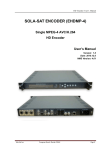
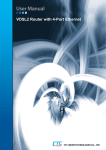
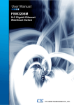
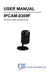
IFC-Serial, IFC-Serial-E
Industrial Fiber Converter
LEGAL
The information in this publication has been carefully checked and is believed to be entirely accurate at the time of
publication. CTC Union Technologies assumes no responsibility, however, for possible errors or omissions, or for any
consequences resulting from the use of the information contained herein. CTC Union Technologies reserves the right to
make changes in its products or product specifications with the intent to improve function or design at any time and
without notice and is not required to update this documentation to reflect such changes.
CTC Union Technologies makes no warranty, representation, or guarantee regarding the suitability of its products for
any particular purpose, nor does CTC Union assume any liability arising out of the application or use of any product
and specifically disclaims any and all liability, including without limitation any consequential or incidental damages.
CTC Union products are not designed, intended, or authorized for use in systems or applications intended to support or
sustain life, or for any other application in which the failure of the product could create a situation where personal injury
or death may occur. Should the Buyer purchase or use a CTC Union product for any such unintended or unauthorized
application, the Buyer shall indemnify and hold CTC Union Technologies and its officers, employees, subsidiaries,
affiliates, and distributors harmless against all claims, costs, damages, expenses, and reasonable attorney fees arising
out of, either directly or indirectly, any claim of personal injury or death that may be associated with such unintended or
unauthorized use, even if such claim alleges that CTC Union Technologies was negligent regarding the design or
manufacture of said product.
TRADEMARKS
Microsoft is a registered trademark of Microsoft Corp.
HyperTerminal™ is a registered trademark of Hilgraeve Inc.
WARNING:
This equipment has been tested and found to comply with the limits for a Class A digital device, pursuant to Part 15 of
the FCC Rules. These limits are designed to provide reasonable protection against harmful interference when the
equipment is operated in a commercial environment. This equipment generates, uses, and can radiate radio frequency
energy and if not installed and used in accordance with the instruction manual may cause harmful interference in which
case the user will be required to correct the interference at his own expense. NOTICE: (1) The changes or modifications
not expressively approved by the party responsible for compliance could void the user's authority to operate the
equipment. (2) Shielded interface cables and AC power cord, if any, must be used in order to comply with the emission
limits.
CISPR PUB.22 Class A COMPLIANCE:
This device complies with EMC directive of the European Community and meets or exceeds the following technical
standard. EN 55022 - Limits and Methods of Measurement of Radio Interference Characteristics of Information
Technology Equipment. This device complies with CISPR Class A.
WARNING:
This is a Class A product. In a domestic environment this product may cause radio interference in which case the user
may be required to take adequate measures.
CE NOTICE
Marking by the symbol CE indicates compliance of this equipment to the EMC directive of the European Community.
Such marking is indicative that this equipment meets or exceeds the following technical standards: EN55022 Class A,
EN61000-4-2 ESD Level 3, EN61000-4-3 RS Level 3, EN61000-4-4 EFT Level 3, EN61000-4-5 Surge Level 3,
EN61000-4-6 CS Level 3.
CTC Union Technologies Co., Ltd.
Far Eastern Vienna Technology Center (Neihu Technology Park)
8F, No. 60, Zhouzi St.
Neihu, Taipei, 114
Taiwan
Phone: +886-2-2659-1021
FAX: +886-2-2799-1355
IFC-Serial, IFC-Serial-E
Industrial Grade RS-485 / RS-422 / RS-232 Fiber Media Converter
User Manual
Version 1.1 December 23, 2013 (Update Release)
This manual supports the following models:
IFC-Serial
IFC-Serial-E
This document is the current official release manual. Please check CTC Union's website for any updated manual or
contact us by E-mail at [email protected]. Please address any comments for improving this manual or to point out
omissions or errors to [email protected]. Thank you.
©2012~2013 CTC Union Technologies Co., Ltd.
All Rights Reserved
The contents of this document are subject to change without any prior notice.
Table of Contents
CHAPTER 1. INTRODUCTION ....................................................................................................................................7 1.1 WELCOME ..................................................................................................................................................................7 1.2 PRODUCT DESCRIPTION .............................................................................................................................................7 1.2.1 Features .............................................................................................................................................................7 1.2.2 Specifications .....................................................................................................................................................7 1.2.3 Block Diagram ...................................................................................................................................................8 1.2.4 Theory of Operation...........................................................................................................................................9 1.2.5 Applications .......................................................................................................................................................9 1.2.6 RS-485 4 wire vs. 2 wire ....................................................................................................................................9 1.2.7 RS-485 Termination ...........................................................................................................................................9 1.2.8 RS-485 Pull High, Pull Low.............................................................................................................................10 CHAPTER 2. INSTALLATION....................................................................................................................................11 2.1 DIN RAIL MOUNTING ...............................................................................................................................................11 2.1.1 Bracket Mounting.............................................................................................................................................11 2.1.2 Rail Mounting ..................................................................................................................................................11 2.1.3 Rail Dismounting .............................................................................................................................................12 2.2 WALL MOUNTING .....................................................................................................................................................12 2.3 ELECTRICAL INSTALLATION.....................................................................................................................................13 2.3.1 DC Power.........................................................................................................................................................13 2.3.2 Alarm Contact ..................................................................................................................................................13 2.4 RS-485/422 CONNECTIONS ......................................................................................................................................14 2.5 RS-232 CONNECTIONS .............................................................................................................................................14 2.6 FIBER CONNECTION .................................................................................................................................................14 CHAPTER 3. CONFIGURATION AND OPERATION.............................................................................................15 3.1 CONFIGURATION ......................................................................................................................................................15 3.1.1 DIP Switch .......................................................................................................................................................15 3.1.2 Pull High/Low ..................................................................................................................................................16 3.1.3 LED Definitions ...............................................................................................................................................16 3.2 OPERATION ..............................................................................................................................................................17 3.2.1 Two Unit Point-to-Point...................................................................................................................................17 3.2.2 One-way Daisy Chain ......................................................................................................................................17 3.2.3 Three or more units Ring Topology .................................................................................................................18 i
Table of Contents
This page left blank intentionally
ii
Chapter 1 Introduction
Chapter 1. Introduction
1.1 Welcome
Thank you for purchasing our IFC-SERIAL fiber port serial media converter. This media converter is an "industrial
strength" product that employs rugged mechanical materials and construction, component selection for wide
temperature, highly reliable and long life operation and an electrical design that prevents internal damage or data
disruption from surges, power spikes or other electromagnetic interference.
1.2 Product Description
The IFC-SERIAL are industrial grade fiber media converters that provides a fiber connection to extend asynchronous
RS-232, RS-485 or RS-422 serial transmissions over a distance of up to 2km using multimode fiber or up to 60km
using single mode fiber. The duplex fiber provides point-to-point connections. Single fiber simplex connections allow
connecting multiple devices in a cascaded or "daisy chain" fashion with a single fiber ring architecture. However, no
redundancy is provided and any break can disable the entire ring. The converter is capable of selecting interface modes
for connection to RS-232 (3 wire), RS-485 (2 wire, half duplex) or RS-422/485 (4 wire, full duplex).
The IFC-SERIAL Series secures asynchronous serial data transmissions over EMI resistant fiber at speeds up to
1024kbps. IFC-SERIAL Series media converters feature an alarm relay contact and two redundant DC power inputs.
The IFC-SERIAL Series reliable industrial design is perfect for keeping your industrial automation applications running
smoothly and continuously. The IFC-FCD Series media converters are available in two operating temperature ranges, a
standard -10° to 60°C commercial temperature range or an extended -40° to 75°C range (IFC-SERIAL-E).
1.2.1 Features
Extends serial transmissions up to 2km, 30km or 60km
Supports fiber daisy chain or ring connections (half-duplex)
Redundant dual power inputs 12/24/48VDC
Supports RS-422, RS-485(2/4 wire), and RS-232 transmission to dual fiber connections.
Enhanced serial baud rate up to 1024kpbs (RS-422/485) or 230.4kbps (RS-232)
2.5KV isolation for serial signals
Supports relay output for power or fiber link failure warning
Hardened housing with IP30 protection
Fan-less and DIN-Rail design for harsh industrial environments
Adjustable pull high/low resistor and terminator for RS-422/485 transmission
1.2.2 Specifications
Optical Interface
Connector : SC or ST
Fiber Optical data rate : 50.000Mbps
Fiber Optical line coding : 4B5B + NRZI
Fiber Port : One duplex fiber port
Fiber Type : MM 2km or SM 30km/60km (duplex fiber)
Wavelength : MM 1310nm, SM 1310, 1550nm
Point to Point Transmission : Half or Full duplex
Ring Transmission : Simplex, Half duplex
Electrical Interface
Serial Connectors : RS-422/RS-485(5 pin terminal)
RS-232(DB9 Female)
RS-485 : 4, 2 wires, RS-422 : 4 wires
RS-485 direction : Automatic detection
Copper Baud rate : 50 up to 1024Kbps (RS-422/485), 230.4Kbps (RS-232-CH1), 115.2Kbps (RS-232-CH2)
Serial Isolation : 2.5KV for serial signals
Surge Protection : 8KV ESD for serial signals
Pull High/ Pull Low : selected by 10 position rotary switches
120 ohm terminator : Option by Dip switch
7
Chapter 1 Introduction
Alarm Contact
One relay output with current carrying capacity of 0.5A @ 125VAC or 1A @ 30 VDC (resistive)
Power
Power Input : 12, 24, 48 VDC (9.6 ~ 58VDC absolute)
Power Consumption : 5W
Power Reversal Protection : Yes
Over Current Protection : Signal Short Together Protected
Terminal Block for Power and Alarm : Yes
Physical Characteristics
Metal Housing
Water & Dust : IP30 Protection Rating
Dimensions : 106 x 39 x 142mm (D x W x H)
Net Weight : 720g
Mounting : DIN-Rail mounting, Wall Mounting (kits included)
Environmental Limits
Operating Temperature:
Standard IFC-SERIAL Model: -10°C ~ 60°C (14 to 140°F)
Wide Temp. IFC-SERIAL-E Model: -40°C ~ 75°C (-40 to 167°F)
Storage Temperature -40 to 85°C (-40 to 185°F)
Relative Humidity: 5 ~ 95%
Certifications
Safety : UL508 (Pending)
EMC : CE, FCC
EMI : EN55022 Class A
EMS: EN61000-4-2 ESD Level 3
EN61000-4-3 RS Level 3
EN61000-4-4 EFT Level 3
EN61000-4-5 Surge Level 3
EN61000-4-6 CS Level 3
Free Fall : IEC 60068-2-32
Vibration : IEC 60068-2-6
Shock : IEC 60068-2-27
Green : RoHS
MTBF : 797,101 Hrs
1.2.3 Block Diagram
The IFC-SERIAL has a configurable 2-wire / 4-wire RS-485/422 interface and two RS-232 3-wire interfaces. The
two RS-232 interfaces share a common ground but are isolated from power ground and from the RS-485/422 interface
by 2.5KV isolation. The RS-485/422 interface is also isolated from power ground and from the RS-232 signals by
2.5KV isolation.
A triple way interface converter, with isolation, is created between the RS-422/485 and Channel 1 RS-232. The
second RS-232 channel is independent and can carry data separately from the first channel.
Basic block diagram of IFC-SERIAL (for reference only)
8
Chapter 1 Introduction
1.2.4 Theory of Operation
The IFC-SERIAL uses control logic to connect an RS-485/422 interface, two RS-232 3-wire interfaces to a single bidirectional optical fiber channel. IFC-SERIAL units are interconnected by the fiber port in point-to-point applications.
A simplex fiber can form a ring topology, but without protection. The IFC-SERIAL uses Master/Slave hierarchy where
only one master unit exists and all other units are slave in the application. In an 'idle' condition, all interfaces are in a
listening state. When any one receive interface receives data transmission, IFC-SERIAL will broadcast and transmit out
across all units and transmit interfaces. The IFC-SERIAL operates completely at the physical layer, transparent to
communication protocols. The communication protocols are required to handle bi-directional data flow control and
device addressing.
1.2.5 Applications
RS-485 signals are used in a wide range of computer and automation systems. RS-485 is used for low-speed data
communications and the physical layer underlying many standard and proprietary automation protocols used to
implement Industrial Control Systems, including the most common versions of Modbus and Profibus. The Profibus
(Process Field Bus) protocol uses RS-485 physical medium when deploying field bus solutions in factory and process
automation environments. Since RS-485 signals are differential, they resist external electromagnetic interference from
motors and welding equipment.
In theatre and performance venues, RS-485 networks are used to control lighting and other systems using the
DMX512 protocol.
In surveillance, RS-485 is used to control pan tilt zoom (PTZ) cameras via Panasonic, Pelco D/P, Samsung and Sony
protocols.
RS-485 is also used in building automation as the simple bus wiring where long cable length is ideal for joining
remote devices. RS-485 may be used to control video surveillance systems or to interconnect security control panels
and devices such as alarm sensors, intrusion devices or access control card readers.
The IFC-SERIAL uses a complete galvanically isolated full duplex RS485/RS422 transceiver. Coupled inductors and
an isolation power transformer provide 2500VRMS of isolation between the line transceiver and the logic interface.
This converter is ideal for systems where the ground loop needs to be broken to allow for large common mode voltage
variation.
1.2.6 RS-485 4 wire vs. 2 wire
RS-485 is a multipoint specification and uses a half-duplex, 2-wire communication connection. RS-485 drivers need
to be put in transmit mode explicitly by asserting a signal to the driver. When not transmitting, the drivers present a high
impedance on the wire pair. The protocol layer must handle transmission to avoid two devices "talking" at once.
When switching the RS-485 to 4-wire mode, we actually are making an RS-422 interface which is full duplex and
with separate TX and RX wire pairs. In 4-wire mode, the transmit drivers are always enabled. This means that 4-wire
mode is only applicable for point-to-point applications and cannot be used in multipoint applications.
1.2.7 RS-485 Termination
Depending on the wire gauge of the cable and the materials used in the insulation, twisted-pair wire has
"characteristic impedance" associated with it that is usually specified by the cable manufacturer. The RS-485
specification recommends, but does not specifically dictate, that this "characteristic impedance" be 120Ω.
Because of the high frequencies and the distances involved, proper attention must be paid to transmission-line effects.
A detailed discussion of transmission-line effects and proper termination techniques is well beyond the scope of this
user manual. With this in mind, terminations will be briefly discussed in their simplest form as they relate to RS-485.
9
Chapter 1 Introduction
A terminating resistor is simply a resistor placed at the extreme end or ends of a cable. The value of the terminating
resistor is ideally the same value as the characteristic impedance of the cable. In the IFC-SERIAL, this value is fixed at
120Ω.
When no termination resistance is applied to the wiring, reflections will occur as the signal travels down the cable.
Although some reflections are inevitable due to cable and resistor tolerances, large enough mismatches can cause
reflections big enough to cause errors in the data.
Knowing this, it is important to match the terminating resistance and the characteristic impedance as closely as
possible. The position of the terminating resistors is also very important. As a general rule, termination resistors should
be placed at both far ends of the cable. Although properly terminating both ends is absolutely critical for most system
designs, it can be argued that in one special case only one termination resistor is needed. This case occurs in a system
when there is a single transmitter and that single transmitter is located at the far end of the cable. In this case there is no
need to place a termination resistor at the end of the cable with the transmitter, because the signal is intended to always
travel away from this end of the cable.
1.2.8 RS-485 Pull High, Pull Low
Somewhere along the set of wires, pull up or pull down resistors are established to fail-safe bias of each data
line/wire when the lines are not being driven by any device. This way, the lines will be biased to known voltages and
nodes will not interpret the noise from un-driven lines as actual data. Without biasing resistors, the data lines may float
in such a way that electrical noise sensitivity is greater when all device stations are silent or unpowered.
The IFC-SERIAL uses rotary switches to select from ten different bias resistor values. The factory default setting is
at position 4. The factory default provides bias resistors of 1KΩ in the pull high and pull low positions. When changing
the rotary switches, it is important to maintain the same setting on both switches.
The following electrical circuit shows the locations of the pull high, pull low bias resistors, the terminating resistor
and the relationship of transmitter and receiver in a 2-wire half duplex RS-485 application.
VCC
Pull High
TX
terminator
Pull Low
1KΩ (default)
120Ω
1KΩ (default)
RX
Pull High / Pull Low Bias Resistors and Termination
10
Chapter 2 Installation
Chapter 2. Installation
The IFC-SERIAL offers two mounting options; DIN Rail mounting or Wall mounting. For each, a different mounting
bracket is required. Both mounting option brackets are included with the IFC-SERIAL.
2.1 DIN Rail mounting
2.1.1 Bracket Mounting
To support DIN Rail mounting, the IFC-SERIAL must first have the DIN Rail bracket installed. Position the bracket,
as shown below, and use the two provided flathead screws to attach the bracket to the center two mounting holes. Note
the alignment pin of the bracket must align with the hole in the IFC-SERIAL.
alignment
hole
2.1.2 Rail Mounting
Place the IFC-FCD's bracket over the top rail of DIN rail. Swing the unit into position [1] and snap the unit in place
by placing a slight downward pressure [2] until the bottom of the bracket locks with the lower rail.
Rail mounting the IFC-SERIAL
11
Chapter 2 Installation
2.1.3 Rail Dismounting
To remove the IFC-SERIAL unit, use a slight downward pressure [1] and release the lower rail from the IFCSERIAL's bracket. Swing the unit out [2] and lift off and away from the DIN rail.
Rail dismounting the IFC-SERIAL
2.2 Wall mounting
To support wall mounting, the IFC-SERIAL must first have the wall mount bracket installed. You may use the
bracket as a template for locating and drilling (if necessary) the wall mounting holes, prior to assembly. After preparing
the wall mount location, attach the wall mount bracket to the IFC-SERIAL, as shown below. Use the two provided
flathead screws to attach the bracket to the outer two mounting holes.
The wall mount bracket is attached with two screws
12
Chapter 2 Installation
2.3 Electrical Installation
The electrical, signal and optical connections will be explained here. The DC power, alarm and RS-485 connections
all use terminal blocks. A flat blade screwdriver (with blade width of ~2 mm) is required to secure the wiring in the
terminal blocks.
2.3.1 DC Power
There are input connectors for two power sources. Only one power source is required for normal operation. The
second power source input may be provided for redundancy. When operating in a critical environment, connecting to
two separate power sources will ensure non-stop operation even in the event that one power source fails.
The power inputs are protected against reverse polarity connections, in fact they will actually work if power is reverse
connected. However, we highly recommend following the proper polarity connection for power. Not all devices are
designed with such protection features as the IFC-SERIAL.
Physical connections for two power inputs
2.3.2 Alarm Contact
The IFC-SERIAL has a single, normally open / normally closed alarm relay contact. Depending on some DIP switch
settings, this alarm contact can create a closed or open circuit when conditions such as power failure or fiber disconnect
occurs. The alarm contact is capable of carrying up to 1A @ 24VDC and can be used to complete or break a circuit for
a visible or audible alarm.
Physical connections for relay contacts
13
Chapter 2 Installation
2.4 RS-485/422 Connections
The IFC-SERIAL provides terminal connections for the twisted pair RS-485 interface wiring. When using 4-wire
RS-485 or RS-422, connect transmit and receive pairs as indicated in the table under "4-Wire Mode". When using 2wire RS-485, connect the single wire pair with the polarity indicated in the table under "2-Wire Mode".
Pin
1
2
3
4
5
4-Wire Mode
Ground
TX- (transmit minus)
TX+ (transmit plus)
RX- (receive minus)
RX+ (receive plus)
2-Wire Mode
Ground
--------TRX- (Tx/Rx minus)
TRX+ (Tx/Rx plus)
2.5 RS-232 Connections
The IFC-SERIAL uses a 9 pin D-Sub female connector for RS-232 connections. This D-Sub connects to one RS-232
channel (using only 3-wire) by the standard pins 2(TD), 3(RD) & 5(SG). A second RS-232 channel uses non-standard
pin assignment, utilizing the pins normally used for handshaking, 7(RD), 8(TD) & 5(SG).
9
Pin
1
2
3
4
5
6
7
8
9
5
6
1
Function
Ch1 TD
Ch1 RD
GND
Ch2 RD
Ch2 TD
2.6 Fiber Connection
The IFC-SERIAL is available with fiber connectors for SC or ST and for multi-mode or single mode fiber. The fiber
connection require duplex cables and proper adherence to connections for RX and TX. The following table describes
the attributes of the various transceivers available for the IFC-SERIAL.
Connector
Type
SC or ST
SC or ST
SC or ST
Wavelength
Media
1310nm
1310nm
1310nm
MMF
SMF
SMF
Optical TX
Power
-14~-20dBm
-5~-15dBm
0~-5dBm
14
Optical RX
Sensitivity
-31dBm
-35dBm
-35dBm
Power
Budget
11dB
20dB
30dB
Distance
Diode
2KM
30KM
60KM
VCSEL
FP
FP
Chapter 3 Configuration and Operation
Chapter 3. Configuration and Operation
3.1 Configuration
3.1.1 DIP Switch
The IFC-SERIAL uses a 6-pole DIP (dual inline package) switch and two 10-position rotary switches for all
configuration settings. There is no provision for any software configuration.
The DIP switch sets the operational mode, configures alarm and interface operation, while the rotary switches are
used exclusively for the pull high, pull low bias resistors in the RS-422 (RS-485) receive circuits.
Sw
1
2
3
4
5
6
Position
OFF
ON
OFF
ON
OFF
ON
OFF
ON
OFF
ON
OFF
ON
Function
Loss either input power, no alarm
Loss either input power, alarm active
Normal Point-to-Point mode
Simplex fiber ring mode
Slave
Master
4-Wire
2-Wire
Disable
Enable
OFF
120Ω
Operation Mode
RS-485 Mode
Ring Alarm
Termination (RS-485)
Switch 1 : When connecting the IFC-SERIAL to only a single power source, leave this switch OFF or the alarm will be
constantly on. When connecting to two separate power sources, turn this switch ON and alarm will occur if either power
source fails.
Switch 2 : The normal point-to-point operation of the IFC-SERIAL should leave this switch OFF. When set to ON, the
converter can be set in a simplex ring with multiple units. By simplex fiber we mean the transmit fiber of one IFCSerial goes to the receive of another IFC-Serial. Then its transmit fiber connects to yet another unit until the last
transmit fiber connects to the original IFC-Serial. This completes a ring, but only with a single fiber. No redundancy is
supported and any single fiber breakage or IFC-Serial powered off would bring down all transmission. So, please use
this mode with care and some forethought.
Switch 3 : In any application, using two or more IFC-SERIAL, one unit should be set to 'Master' mode and all other
units must be set to 'Slave'.
Switch 4 : This switch sets the RS-485 to either 2-wire or 4-wire operation. In 2-wire operation, connect the wire pair to
only the RX+ and RX- connections.
Switch 5 : This switch should only be enabled when the IFC-SERIAL has its fiber connected in a ring topology. Then,
when enabled, if any break occurs in the fiber ring, the alarm is become active. For point-to-point or linear topology,
disable this switch or alarm will be constantly active.
Switch 6 : This switch enables the internal signal termination by placing a 120 ohm resistance across the RX
complimentary pair. (Refer to Chapter 1 Section 1.2.7 for more detailed description of termination.)
15
Chapter 3 Configuration and Operation
3.1.2 Pull High/Low
The pull high / pull low bias is explained in more detail in Chapter 1 Section 1.2.8. The bias resistance should be set
to position setting no.4 for 1KΩ from the factory. It is highly recommended to set both high and low rotary switches to
the same setting. Using different settings will put an unequal bias on the circuit and could cause more noise by
unbalancing the common-mode rejection capability of the balanced transmission wire pair.
The following graphic shows the two Pull High, Pull Low rotary switches in the no. 0 position. The table lists the
bias resistor values for the rotary switch positions.
Position
0
1
2
3
4
5
6
7
8
9
Resistance (Ohms)
100K
9.9K
5K
3.3K
1K (default)
920
840
774
500
475
3.1.3 LED Definitions
The front panel has a 3 x 3 matrix of 2.5mm LEDs. The LEDs are used to quickly diagnose the link and alarm
condition of the IFC-SERIAL.
The following table lists and describes the meanings of the LEDs.
LED
Color
State Definition
OFF
Normal operation with no alarms
ALM
Red
ON
Alarm exists for power or fiber link**
OFF
There is no DC power at PWR2 input
PWR2 Green
ON
DC power normal at PWR2 input
OFF
There is no DC power at PWR1 input
PWR1 Green
ON
DC power normal at PWR1 input
OFF
Transmit data is idle (Mark)
TD
Green
ON
There is data transmitted (Space)
OFF
Receive data is idle (Mark)
RD
Green
ON
There is data being received (Space)
OFF
Configured in Slave mode
Master Green
ON
Configured in Master mode
OFF
Ring failure
Ring
Green
ON
Ring OK
OFF
reserved
Green
ON
reserved
OFF
Fiber has no link
Fiber1 Green
ON
Fiber has optical link
** Depends on the settings of DIP switch 1, 2 &5 for alarm reporting.
16
Chapter 3 Configuration and Operation
3.2 Operation
The following examples are for reference and as an aid in understanding the operating modes and DIP switch
selections of the IFC-SERIAL converter.
3.2.1 Two Unit Point-to-Point
In the very simplest application, a duplex fiber connects two IFC-SERIAL units. One unit is set as 'Master' the other
as 'Slave'. The RS-485 and RS-232 are completely isolated electrically. A receive signal can only be connected to either
the RS-485 (terminal block) or to the RS-232 DB9 (not both at the same time). That received signal will be transmitted
simultaneously on every transmit connection, both RS-485 and RS-232.
In the example below, the 'Master' unit is receiving RS-485 serial signal. The signal is repeated out of every other
transmit pin.
RS-485 (in)
RS-485 (out)
RS-232 (out)
RS-232 (out)
Master
Slave
3.2.2 One-way Daisy Chain
In this application, data transmission only occurs one-way. When used in this manner, data can be transmitted from a
host (at the master unit) to all remote devices. These devices could be connected to text displays in public venues such
as in rail or bus terminals or for warning signs along highways. The data from the host can be used to continuously
update the displayed text information.
In the application, one unit is set as 'Master' and others as 'Slave'. The RS-485 and RS-232 are completely isolated
electrically. A receive signal can only be connected to either the RS-485 (terminal block) or to the RS-232 DB9 (not
both at the same time). That received signal will be transmitted simultaneously on every transmit connection, both RS485 and RS-232.
In the example below, the 'Master' unit is receiving RS-485 serial signal. The signal is repeated out of every other
transmit pin.
RS-485 (in)
RS-485 (out)
RS-485 (out)
RS-485 (out)
RS-232 (out)
RS-232 (out)
RS-232 (out)
RS-232 (out)
TX
TX
TX
RX
RX
RX
Master
Slave
Slave
17
TX
RX
Slave
Chapter 3 Configuration and Operation
3.2.3 Three or more units Ring Topology
CAUTION : This application provides no fiber redundancy. In the event of any one fiber link loss, or any device
powered off, 2-way transmission between all the devices will not be possible. Depending on where the link is broken,
there still may be transmit or receive path between some devices. A better product for this ring topology would be the
IFC-FDC product which supports dual fiber ports.
In the single fiber ring topology, the fiber transmit of one device connects to the fiber receive of the next device.
Then its fiber transmit again connects to the next device fiber receive, until a completed ring is formed.
The IFC-Serial operates completely at Layer 1. However, the logic control will ensure that any transmitted data will
flow to each device in the ring but will not loop. The protocol layer is required to handle proper communication flow
control. Reception of data at any receive should only be allowed from one device at a given moment. That received data
will then be broadcast (transmitted) to all units and interfaces out.
In the example below, one RS-232 interface receives data and it is broadcast to all other interfaces.
RS-485 (out)
RS-232 (out)
TX
RX
Master
RS-485 (out)
RS-485 (out)
RS-232 (in)
RS-232 (out)
TX
TX
RX
RX
RS-485 (out)
Slave
RS-232 (out)
TX
RX
Slave
18
Slave