1
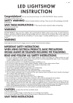
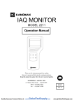
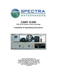
USER’S GUIDE
TABLE OF CONTENTS
INTRODUCTION……………………………………………………………….3
WARRANTY INFORMATION…………………………………………………4
SAFETY INFORMATION………………………………………………………5
PREPARING YOUR WATER BEFORE INSTALLATION…………………6
TOOLS AND PARTS REQUIRED FOR INSTALLATION…………………7
INSTALLING YOUR SYSTEM – PLUMBING………….………………….8-9
-
ELECTRICAL………….………………10
SPECIFICATIONS AND FUSE SIZING……………………………………..11
STARTING THE SYSTEM………………………………………………….…12
GENERAL OPERATION………………………………………………………13
MAINTENANCE AND CLEANING…………………………………………..14
WATER CHEMISTRY AND TESTING………………………………………15
2
INTRODUCTION
ChlorKing® inc
6767 Peachtree Ind. Blvd, Suite G
Norcross, Georgia, 30092
1-800-536-8180
Patent # US 6821398B2
EPA Est. # 082229-GA-001
NSF-50 / UL-1081 listed
Congratulations on purchasing your new ChlorKing® saline chlorination system,
we trust that this system will offer you the ultimate in swimming environments,
and give you years of trouble free operation.
This user’s manual will explain in detail the operation of your new system, as well
as water chemistry guides, warranty information, and much more.
If at any time you need additional information on your system, please feel free to
contact us.
ChlorKing® models available:
*Mini-1.25
*Mini-2.0
*Mini-2.5
(1.25lbs / day)
(2.0lbs / day)
(2.5lbs / day)
*Chlor-1.5
*Chlor-2.5
*Chlor-3.5
*Chlor-5.0
*Chlor-7.5
*Chlor-10
*Chlor-15
*Chlor-20
*Chlor-25
(1.5lbs / day)
(2.5lbs / day)
(3.5lbs / day)
(5.0lbs / day)
(7.5lbs / day)
(10lbs / day)
(15lbs / day)
(20lbs / day)
(25lbs / day)
(Lbs / day production based on amount
of equivalent chlorine produced in 24
hours)
certified
Classic-1.5
Classic-2.5
Classic-3.5
Classic-5.0
Classic-7.5
Classic-10
Classic-15
Classic-10
Classic-25
(1.5lbs / day)
(2.5lbs / day)
(3.5lbs / day)
(5.0lbs / day)
(7.5lbs / day)
(10lbs / day)
(15lbs / day)
(20lbs / day)
(25lbs / day)
(*Mini & *Chlor systems feature reverse
polarity which reduces the frequency of
manual cleaning required)
3
WARRANTY INFORMATION
The ChlorKing® system carries a limited 3 year warranty
1. 3 year warranty on assembly of electrical components and cell
housing.
2. 1 year on all electrical items.
3. 2 years or 15,000 hours, which ever occurs first, pro-rated hourly,
on titanium electrodes. (Year 1 is warranted fully, thereafter prorated warranty applies, applicable over the full 2 year period)
•
ChlorKing® advises that titanium electrodes will have to be replaced
every 15,000 hours of operating time. Under no circumstances shall the
replacement titanium electrodes exceed the original 15,000 hour warranty.
•
ChlorKing® warranties will not be honored should it be shown that the
operating and maintenance procedures have not been followed,
particularly with regard to the correct maintenance of salt concentration
and water chemistry.
•
ChlorKing® warranties of the titanium electrodes will not be honored if
the system is operated in water temperatures lower than 59 degrees F.
•
ChlorKing® warranties of the titanium electrodes will not be honored if
the system is operated in water where the salt concentration is lower than
3000 ppm.
•
During the warranty period the customer shall return the defective
component, freight prepaid, accompanied by the original invoice or proof
of purchase, and ChlorKing® shall at it’s sole discretion elect to repair or
replace the defective component and return it to the customer, freight prepaid.
ChlorKing® accepts no responsibility other than to repair or replace a defective
component, and this warranty specifically excludes product failure due to
accidental damage, abuse, misuse, negligence, damage due to non-compliance
of the operating manual or unauthorized alterations or modifications to the
system. ChlorKing® accepts no responsibility and is not liable for any extended
warranties or variations to this warranty offered by re-sellers of ChlorKing®
systems.
SAFETY INFORMATION
PLEASE READ THE FOLLOWING SAFETY INFORMATION CAREFULLY!
WARNING!
•
Only a certified technician may install and service your ChlorKing®
system.
•
Modifying your ChlorKing® system in anyway may cause bodily injury
and will void your warranty.
•
Do not allow children to operate your ChlorKing® system.
•
Only replace components with those specified by manufacturer.
•
When installing your system, ensure that power is linked to the main pump
power source for the pool to ensure that your ChlorKing® system never
operates when the pumps are off.
•
All boxes on your ChlorKing® system contain high voltage components.
Never open any box while power is “on”.
5
PREPARING YOUR WATER BEFORE INSTALLATION
ChlorKing® saline chlorination systems operate by utilizing the sodium chloride
that has been added to the pool water, to produce sodium hypochlorite (liquid
chlorine), through the process of electrolysis.
In order for your ChlorKing® system to operate correctly, sodium chloride (salt)
must be added directly to the pool at least 24 hours before the installation of the
equipment.
40lbs of sodium chloride must be added for every 1,000 gallons of pool water
(ie: a 50,000-gallon pool will require 50 x 40lb bags of salt for start-up).
It is best to add the salt around the pool, and not load all salt in one section.
Once the salt has been added, brush the surface of the pool continuously until
the salt has all dissolved. You must never leave large amounts of salt on the
surface of the pool, as this may cause damage to the pool surface.
When you add the initial load of salt, you will need to add additional chlorine, as
the salt will cause a chlorine demand.
Your pool water should be balanced in the following range before turning your
ChlorKing® system on;
Chlorine:
Total Chlorine:
Ph:
Alkalinity:
Hardness:
Salt:
Cynuric acid:
Phosphates:
2 – 5 ppm
No more than 0.5 ppm above free chlorine
7.2 – 7.6
80 – 120
180 – 280 ppm
4500 – 5500 ppm
20 – 50 ppm (Outdoor Pools only)
Less than 100 ppm
Use standard test kits to check water chemistry, and use either a conductivity
tester or salt test strip to check saline levels.
(Note that most conductivity testers require frequent calibration to ensure
accurate readings, failure to calibrate the equipment will result in
inaccurate readings.)
6
TOOLS AND PARTS REQUIRED FOR INSTALLATION
Your ChlorKing® system will include an installation kit comprising of the
following items:
Description
Strainer 1” clear bowl with 20
mesh
PVC 1” ball valve Sch. 40
PVC 1” male adaptor Sch. 40
PVC nipple 1” x 2” SCH 80
PVC bushing 1” x ¾” Threaded
PVC union 1” S EPDM w/o
O-ring Sch. 80 threaded
Akenstrut clamps 3”, 6” or 8”
Polypropylene valve, speed fit
3/8 x 3/8 NPTF
Elbow street 90, SCH 80 1”
Salt test strips
Qty
1
2
4
2
1
2
** The CHLOR-25 system will
comprise of 1½” installation
kits.
2
2
2
1
Additionally you will need the following items, not included, to complete
the installation:
•
•
•
•
3/8” Polypropylene tubing
1” Flex PVC tubing
Wall anchors
Disconnect box, fuse box, conduit, wiring and related material to supply 220v to systems
(220v systems only)
The following tools will be required to complete the installation:
Power Tools
Drill Bits
Drill
Hammer Drill
1 1/8” hole saw
9/16” paddle bit
Steel bit drill set
¼” mason bit
Hand Tools
Taps
Set of sockets up to 1 1/16”
Hammer
Screw Drivers – Flat & Phillips
Wire Strippers
PVC Cutters to 1 ¼”
24” Level
2 x 8” slip joint pliers
Crescent wrench
¾” wrench
9/16” wrench
Black Electrical Tape
1” NPT
3/8” NPT
Hand Tools cont..
Tape Measure
Teflon Tape
Allen Wrenches
True RMS Clamp Meter
Wire Cutters
7
PLUMBING YOUR SYSTEM
Your ChlorKing® system can be plumbed using two different methods. Both will
work fine, however, the following must be taken into account before making the
decision of what method to use.
1. Your ChlorKing® system requires a minimum of 20gpm of flow through the
cell to produce the rated amount of chlorine. Be sure that if you use the
pressure drop plumbing method [1] you have sufficient pressure drop across
your filter to adequately flow 20gpm through the cell.
2. When using the pressure drop plumbing method [1], you are sending
un-filtered water through the cell, so you need to ensure that you clean the
included strainer at least 1 time per week to remove any debris. Failure to
clean the strainer will result in a lack of flow, reducing chlorine production, and
ultimately reducing flow to the point that the flow switch de-activates the
system.
3. If you elect to use the bypass plumbing method [2], you will need to purchase
a butterfly valve based on the size of the pipe you are using. This can
sometimes be cost prohibitive, but the upside of this plumbing method is that
you are sending filtered water through the cell, which reduces the frequency of
needing to clean the strainer. Bypass plumbing method [2] also generally
allows for more flow through the cell, which is recommended.
4. Remember, always ensure that the return line from the ChlorKing® cell is
plumbed after the heater. Never plumb the return line before the heater as you
will be sending a high ppm of chlorine through heater, which may cause
damage.
5. No matter which plumbing method you use, you will always have to plumb the
3/8” cooling line into box 3 (rectifier) using filtered water. This cooling line
allows the heat sink in box 3 to cool the critical components.
8
PRESSURE-DROP PLUMBING METHOD [1]
ChlorKing® power supply
ChlorKing® cell
NOTES:
THE RECTIFIER COOLING LINES MUST BE CONNECTED FROM
THE SUCTION SIDE OF THE PUMP AND AFTER THE FILTER.
ALWAYS USE FILTERED WATER.
IF THERE IS A CONTROLLER PRESENT, THE OUTLET LINE THAT
FEEDS THE CONTROLLER PROBES COULD BE CONNECTED TO
THE RECTIFIER.
BYPASS MANIFOLD PLUMBING METHOD [2]
NOTES:
THE RECTIFIER COOLING LINES MUST BE CONNECTED FROM
THE SUCTION SIDE OF THE PUMP AND AFTER THE FILTER.
ALWAYS USE FILTERED WATER.
ChlorKing® power supply
ChlorKing® cell
ALTERNATIVELY, IF THERE IS A CONTROLLER PRESENT, THE
OUTLET LINE THAT FEEDS THE CONTROLLER PROBES COULD
BE CONNECTED TO THE RECTIFIER.
9
ELECTRICAL SPECIFICATIONS
Each ChlorKing® model has very specific wiring requirements based on its line
voltage and amperage draw.
•
Models that operate at 120v line voltage will have two cables from box 1
(power box) One is labeled 120v and the other ORP. Simply plug the 110v
cord into a regular 120v power outlet that is linked to the pump power
source and is active only when the pump is running, and plug the ORP
cord into the outgoing ORP pigtail from your automatic controller. If you do
not have a controller simply plug the cord labeled ORP into another 120v
power outlet.
•
Models that operate at 208 – 240v require more advanced wiring, which
should only be done by a qualified electrician. 208 – 240v power needs to
be run from your main breaker panel to a safety switch, then into the
ChlorKing® main power box 1. As above, the cord labeled ORP must be
plugged into a controller, or a 120v outlet.
•
Your ChlorKing® system must be wired to the main pump power supply,
so that if the pump is shut down, the power to your ChlorKing® system is
lost.
The table on the following page shows each ChlorKing® model with its required
line voltage, amperage draw, and breaker required.
10
ELECTRICAL SPECIFICATIONS AND FUSE SIZING
MODEL:
Mini-1.25
Mini-2.0
Mini-2.5
Chlor-1.5
Chlor-2.5
Chlor-3.5
Chlor-5.0
Chlor-7.5
Chlor-10
Chlor-15
Chlor-20
Chlor-25
Classic-1.5
Classic-2.5
Classic-3.5
Classic-5.0
Classic-7.5
Classic-10
Classic-15
Classic-20
Classic-25
MAX PRIMARY AC
AMPS
2.5
3.5
4.5
6.9
9.9
13.8 / 6.9
9.9
6.9
9.9
14.9
18.5
20.9
5.5
8.5
5.8
7.9
7.9
9.9
14.9
20.5
24.5
SYSTEM INPUT
VOLTAGE
110v
110v
110v
110v
110v
110v / 220v
110v
208 – 240v
208 – 240v
208 – 240v
208 – 240v
208 – 240v
110V
110V
208 – 240V
208 – 240V
208 – 240V
208 – 240V
208 – 240V
208 – 240V
208 – 240V
BREAKER
REQUIRED
10amp
10amp
10amp
20amp
20amp
20amp
20amp
20amp
20amp
30amp
30amp
30amp
20amp
20amp
20amp
20amp
20amp
20amp
30amp
30amp
30amp
Fuse sizing:
Model
Mini-1.25
Mini-2.0
Mini-2.5
Chlor-1.5
Chlor-2.5
Chlor-3.5
Chlor-5.0
Chlor-7.5
Chlor-10
Chlor-15
Chlor-20
Chlor-25
Classic-1.5
Classic-2.5
Classic-3.5
Classic-5.0
Classic-7.5
Classic-10
Classic-15
Classic-20
Classic-25
Fuse size and type
10amp slow blow glass fuse
10amp slow blow glass fuse
10amp slow blow glass fuse
12amp dual element, slow blow, RK5 fuse
15amp dual element, slow blow, RK5 fuse
12 / 20 amp dual element, slow blow, RK5 fuse
15amp dual element, slow blow, RK5 fuse
15amp dual element, slow blow, RK5 fuse
15amp dual element, slow blow, RK5 fuse
25amp dual element, slow blow, RK5 fuse
30amp dual element, slow blow, RK5 fuse
30amp dual element, slow blow, RK5 fuse
10amp dual element, slow blow, RK5 fuse
15amp dual element, slow blow, RK5 fuse
10amp dual element, slow blow, RK5 fuse
10amp dual element, slow blow, RK5 fuse
15amp dual element, slow blow, RK5 fuse
15amp dual element, slow blow, RK5 fuse
25amp dual element, slow blow, RK5 fuse
30amp dual element, slow blow, RK5 fuse
30amp dual element, slow blow, RK5 fuse
11
STARTING THE SYSTEM
Once your ChlorKing® system has been successfully wired and plumbed, it is
ready for use.
•
•
•
Make sure that the valves to and from the cell are in the open position.
Make sure that you have water flowing through the water-cooled heat sink
in box 3.
Ensure that the cord labeled ORP is either plugged into a controller or
directly into a 110v outlet
1. In 110v systems, move the toggle switch located on the side of box
1, to the “on” position. With 220v systems, move the safety switch
to the “on” position.
2. Wait 10 seconds for the system to respond.
3. Turn the black knob on the side of box 1 clockwise, and watch the
amp or voltmeter on box 3 slowly increase.
(If your system is linked to an automatic ORP controller, we suggest you
turn the system to maximum, which will allow for full production every time
the controller calls for it. If you are running your system manually you will
need to find the point at which you keep a satisfactory level of chlorine in
the water. It may take several days to find this point.
•
If your ChlorKing® system is linked to an automatic controller, remember
that it will only work when the controller is in feed mode. It is also a good
idea to make sure that your controller is not set in proportional band mode,
instead try using double set point control (if your controller supports this
function). An example of this is if you want to maintain a 700 ORP, have
the controller set to turn on at 695 ORP and turn off at 705 ORP, that way
your ChlorKing® system is not switching on and off all the time.
(Call the manufacturer of your controller to discuss how best to set your
system up when working with a saline chlorination system. Most
controllers also require a “gold tip” ORP probe when working with a saline
chlorination system.)
12
GENERAL OPERATION
Your ChlorKing® system operates when power is activated by the main pumps,
and from your ORP controller, and will continue to operate for as long as power
is applied from those two sources.
•
The system has an output range of 5-100% of the rated chlorine
production for that model, and can be adjusted by turning the black knob
of the side of box 1 in a clockwise or anti-clockwise motion. Each model
has a separate maximum operating amperage, as listed below. When
adjusting the control knob on the side of box 1, you will notice the
amperage needle of the gauge on box 3 increases or decreases.
Higher amperage = higher chlorine production.
The table below lists all available ChlorKing® models with each maximum amps
and normal operating volts. (Both amps and volts are DC)
Mini-1.25
Mini-2.0
Mini-2.5
6.25amps @ 15v
10amps @ 15v
12.5amps @ 15v
Chlor-1.5
Chlor-2.5
Chlor-3.5
Chlor-5.0
Chlor-7.5
Chlor-10
Chlor-15
Chlor-20
Chlor-25
30amps @ 4v
50amps @ 4v
70amps @ 4v
25amps @ 15v
37.5amps @ 15v
50amps @ 15v
75amps @ 15v
100amps @ 15v
125amps @ 15v
•
Classic-1.5
Classic-2.5
Classic-3.5
Classic-5.0
Classic-7.5
Classic-10
Classic-15
Classic-20
Classic-25
30amps @ 5v
50amps @ 5v
70amps @ 5v
100amps @ 5v
75amps @ 10v
100amps @ 10v
100amps @ 15v
100amps @ 20v
125amps @ 20v
Water flow through the ChlorKing® cell is critical. Whether you plumbed
your system in using the pressure drop or bypass method, please ensure
that you have at least 20 gpm through the cell to achieve the rated
chlorine production.
** Remember, your ChlorKing® system is a chlorine generator, and will
only operate as well as you maintain it. Careful attention must always be
paid to proper chemical balancing, and regular service.
13
MAINTENANCE AND CLEANING
Your ChlorKing® systems is designed to operate 24/7 at max power, and will
give you years of trouble free use if you follow these basic maintenance and
cleaning instructions.
•
Remember, this system produces sodium hypochlorite “liquid chlorine”
from the salt that you have added to the water. It will only continue to
operate correctly if salt is maintained at the correct 5000ppm level. Low
salt will lower the amount of chlorine produced, and cause damage to the
electrolytic cell. (Warranty’s will not be honored if it is determined that salt has
been run low.)
•
There is a strainer mounted at the bottom of your ChlorKing® cell, which
will trap debris and stop it from entering the cell, this strainer needs to be
cleaned regularly.
•
The plates that are inside the PVC cell housing are the most critical part of
the system. You will notice that over time a white substance (calcium
minerals) will build up on the plates, especially at the top of the cell. This
buildup needs to be cleaned by removing the cell from the housing and
soaking it in a dilute muriatic solution (1:5) for about 10 – 15 minutes.
Classic systems will need to be cleaned every week; reverse polarity
systems will need to be cleaned every 3 – 6 months. (Warranty’s will not be
honored if it is determined that the cell has not been cleaned regularly.)
•
Remember, the titanium plates that make up the cell are the most
expensive part of the ChlorKing® system and are going to need to be
replaced roughly every 15,000 hours of operating time. By ensuring
that salt is always at the correct level, and plates are cleaned
regularly, you will increase their “life”, thus saving you money…
ChlorKing® offers a wide range of other products that can help you maintain salt
levels in your pool, including conductivity controllers and saturated salt feeders
for those pools that loose large amounts of water. Call for more info.
14
WATER CHEMISTRY AND TESTING
The following are the basic parameters for proper water chemistry when using a
ChlorKing® saline chlorination system. (Please always check with your local health
department about their requirements first. Local health regulations MUST always be
followed.)
Daily checks
Free chlorine Total chlorinePh
-
2 – 5 ppm
No more than 0.5 above free chlorine
7.2 – 7.6 (7.4 is ideal)
Weekly checks
Alkalinity
Hardness
Stabilizer
Salt
-
80 – 120ppm
180 – 300ppm
25 – 40ppm (for outdoor pools only)
4500 – 5500ppm
Periodic checks
Phosphates -
no more than 100
Testing can be done using your regular test kit, and the chlorine produced from
your ChlorKing® system will read the same on your test kit as does regular
chlorine.
Testing salt levels can be done using salt test strips or conductivity meters.
(Please remember that storage of salt test strips is critical, as over heat may cause them
to be inaccurate. Most conductivity devices require frequent calibration to be accurate.)
Call ChlorKing® at 1-800-536-8180 to order conductivity testers.
U
15