1
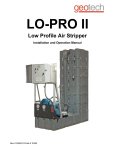
CABO 10,000
With SP-20 Pearson Pump Technology
Installation & Operating Instructions
Spectra Watermakers, Inc.
20 Mariposa Road, San Rafael, CA 94901
Phone 415-526-2780 Fax 415-526-2787
E-mail: [email protected]
www.spectrawatermakers.com
June 2013
2
Table of Contents
Installation Instructions
Page
Getting Started
Introduction
Installation and Setup
Plumbing and Controls
Plumbing Schematic
Electrical Connections
5
6
8
9
10
12
Initial Start-up
Normal Operation
Monitoring the System
12
15
17
Operation
Care and Maintenance
Maintenance
Oil Changes
Long Term Storage
Winterizing
Membranes
Clean-in-Place Procedures
Troubleshooting
18
19
20
21
22
23
24
Wiring Diagram
Specifications
Pump Breakdown
26
29
30
Reference
3
4
Getting Started
Thank you for trusting Spectra Watermakers for your water purification
needs. The Spectra Cabo-10,000 comes equipped with the revolutionary
Spectra Pearson Pump, a unique high pressure pump with integrated energy recovery that allows users to purify up to 420 gallons of seawater per
hour on as little as 3 Kilowatts. If properly installed and cared for, your
system will provide you with years of high quality, potable, fresh water.
Please take a moment to review this manual before
operating the machine and if you have any questions
Contact: [email protected]
Parts List:
•
•
•
•
Cabo 10,000 watermaker
20 and 5 Micron Prefilter Housing Assemblies
Carbon block filter (for flush water)
Service Hose Kit
Any shipping damage must be reported to the carrier within 24 hours of receipt,
so please inspect the contents of your shipment to ensure that all parts have arrived undamaged. It is the responsibility of the receiver to report any missing or
damaged parts to Spectra within one week of taking delivery. Spectra is not responsible for claims made outside this one week window .
5
Introduction to your System
The Spectra Cabo-10,000 watermaker is designed for use in seagoing vessels or platforms. Feed water be supplied to the system a minimum or 20 gpm (76lpm) at 30psi
(2 Bar) pressure. The machine separates the feed water into two streams; product
and brine. The brine stream contains the dissolved solids removed from the product
water. Brine flow may be as high as 13 gpm (50L/min) and should be discharged
above the waterline. The system requires a small amount of back pressure on the
brine stream so plumb the discharge accordingly. Long runs in solid tubing will require
a vacuum break so as to not create any suction at the brine discharge.
Cabo 10,000 frame is constructed of 304 stainless steel and must be positively fixed in
place. includes the Spectra Pearson Pump, Motor and Belt drive system coupled to
three 8” x 40” seawater membranes. All high pressure connections between the membranes and the pump come pre-assembled and tested. The high pressure hoses use
1” JIC 37 deg. flare fittings.
20” Prefilter Housings should be plumbed in Parallel so water flows into both 20 micron filter housings
then through the two 5 micron filter housings. The
filter housing lids have a spring loaded “purge” button
to released air from the filters. Do not install the filters above any electrical devices as some water will
be spilled when changing the filters or purging air.
20” Carbon Block filter housing is used to remove
chlorine from the flush water as chlorine will cause
permanent damage to the membranes.
Boost Pump assembly is to be installed below the water line. The pump
will fail if there is any suction on the
inlet so be sure the pump is completely
flooded at all times.
6
Introduction to your System, cont….
The Control Panel for the Cabo-10,000 (see front view) has a feedwater flow gauge
and valves mounted for easy service access to system . All system parameters are
shown on the MPC 5000 control panel.
Front View
Right Side View
1” Feed Service port/valve
1” Brine Service port/valve
Feed Water flow gauge
3/4” Pressurized Fresh water in
1-1/4” Feed water from filters
1” Brine Discharge
3/4” Product water
Control Box The molded FRP watertight box
contains the “brains” of the Cabo-10,000 which
control the run and flush cycles, activates the
auto store mode, and houses all of the necessary
electronics to run the system. This module
should be kept away from any water source or
where it could get sprayed or wet. Do not operate the machine with the control box open.
Should the need arise to open the electrical box
after installation, use caution as there is live AC
in the box.
7
Installation and Setup
Mounting and Service access: Your Spectra Cabo 10,000 system is designed to be
mounted on a level surface and properly fixed in place. There are cleats supplied with
the system for mounting or holes can be drilled through the frame to bolt it into place.
Be sure to allow for service access to the unit, we recommend:
• A minimum of 40” (1m) to the right of the unit so membranes can be changed.
• A minimum of 24” (60cm) on the front and above the unit.
Cables and Hoses: Route all hoses and power cables in the most direct route possible and do not allow hoses to kink or make excessive bends. Hoses should be supported to take any load off the fittings to reduce leaks caused by vibration. Protect all
cables and hoses against chafing and size all wiring according to industry standards
and local regulations.
CAUTION: Undersized or improperly terminated cabling can result in serious injury or death. Always follow best industry practices when sizing, terminating,
and routing cables and hoses.
Feed Water Boost Pump: The boost
pump must be installed below the water
line. When the outlet of the boost pump
disconnected water should flow out of it.
is
Make sure that the pump is installed in
accordance with local regulations and the
manufacturers specifications.
The Feed Water Pump is controlled by an
AcTech speed control located in the box
on the left side of the unit.
Confirm the boost pump is connected properly and the pump is flooded with water before operating. With pump outlet disconnected water should flow out of
the pump if it is properly installed. There can be no air traps or vertical loops in
the suction hose from the thru-hull (or water box) to the boost pump. The boost
pump has no suction capability and will be damaged if there is a vacuum on the
inlet side when the pump is running.
Note that this should also be tested while the vessel is running at top speed, if
water will not flow through the pump when the outlet is disconnected then there
is suction on line and pump damage will occur.
8
INSTALLATION - Control System
MPC-5000 Controls
(all units)
To protect the microprocessor control
during transport all the connections to
the MPC board are un-plugged prior to
shipping (see picture at right). Prior to
installation plug all connectors into the
nearest receptacle, the harness is tied
together so it is easy to determine what
goes where.
Electrical Cables
The unit is shipped with a length of SO cable to connect to the power source. All units
use 24v DC for the control circuits and a power supply is included in the box.
Optional equipment
Depending on the configuration ordered the system may have an additional control for
relays or speed controls.
Initial power-up
Be sure the toggle switch is in the RUN
AUTO position and the main breaker is
off. When power is applied to the unit
and the main breaker (Emergency ShutOff) is in the on position the display light
up and go through a start up sequence.
The system will sound an alarm and the
red light will flash, press the ALARM/
DISPLAY button to silence the alarm.
The display will read; OPEN PRESSURE
RELIEF VALVE NOW which is part of the
standard start up procedure sequence.
Power the unit off and confirm all plumbing connections are complete.
9
Simplified Plumbing Layout
Feed
Water
Flow
Gauge
Boost
Pump
Filter
Array
Pearson Energy
Recovery Pump
Flush
Valve
Optional
Media
filter
Feed Water
Inlet
High Pressure to
Membranes
High Pressure
Return
Pressurized Fresh
water from tank
Product water
to tank
Membrane Array
Charcoal
filter
Fresh
Water
Pump
Fresh water tank
10
Optional components: Tank Switch Installation and Operation
If your system is ordered with this option there are control wires external to the control
box with a laminated tag for connecting float switches.
For automatic fill and stop…...the unit is wired with both tank full and tank empty
switchs. Enter AutoFill Mode by pushing and holding the Auto Run button on the
MPC-5000 display for 5 seconds. In this mode the system will start whenever one or
both tank switches are open. When the tank fills up and both the tank switches have
remained closed for two minutes, the watermaker will shut down and flush itself. The
water maker will start back up when the water level drops below the tank empty switch
and both remains open for 2 minutes, so this configuration allows for completely automatic operation. If the watermaker does not need to start up within five days it can be
programmed to automatically do a fresh water flush (Contact factory for details). AutoFill mode can be ended by pushing the stop button or the Autoflush button. If the watermaker is in Autorun mode it can be put into Autofill mode without stopping it by
holding down the Autorun button for 5 seconds.
For manual start and automatic stop…….only the tank full switch is used. Jump the
low lever tank switch wires together to enable the high level switch to operate independently, because the watermaker will only shut down if both sets of terminals are
closed. You can start the watermaker by pressing the Autorun button or the Stop button (which s a Start/Stop button) and it will shut off automatically (and do a flush)
when the tank is full. DO NOT press and hold the ‘Auto Run’ button, as this will enter the ‘Auto Fill Mode’ and the watermaker will not function properly.
It is possible to use the Autofill feature with 2 tanks. A double throw electrical switch
must be installed in a convenient location. If only the single tank full switch is installed
in each tank connect the wire From the Float Switch 1 terminal “1” to the common on
the switch and run separate wires from the switch to each tank switch. The second
wires can both be run to the Float Switch 1 terminal 2. If you are using two switches in
each tank you will need a double pole double throw switch.
See wiring schematics beginning on pg.35 for
detailed drawings.
11
New System Startup and Testing (Purging storage chemicals)
Use this procedure when starting a new desalinator for the first time, when the last
known state of the system is unknown, or whenever the system contains Preservative or cleaning chemicals.
Warning! Damage will occur if the purge sequence is bypassed and
the membrane is pressurized with storage chemical in it.
Note: Remove the tape over the Crankcase vent hole and check the oil level before operating the watermaker. Check the dip-stick to confirm the oil level is correct in the
crankcase. Spectra recommends 76 Super Synthetic Blend SAE 5W-30 (ILSAC GF-5).
Caution; Never operate the system with the belt guard removed or the control
boxes open as serious injury could occur.
1. First Check That:
• Feed water is available at the Feed Water Inlet (see
page 7). Confirm both service valves are in the run
position (see picture at right).
• Brine discharge is connected and there are no
restrictions on the line. The brine discharge will contain
a small amount of propylene glycol (potable antifreeze)
until the purge cycle is completed
• Manual/ Auto/ Service Switch is in “Auto” Position
• The crankcase oil level has been checked
• Pressure Relief Valve is OPEN one full turn
• Power is supplied to the control box
2. Turn on main power switch (breaker) on control box.
3. The display will prompt you to “OPEN PRESSURE RELIEF VALVE NOW” so check that
the pressure relief valve is open (unscrewed) 1 full turn.
4. Start the watermaker using Auto Run Button, the boost pump should
start, and the Pearson Pump will run slowly for the first 30 seconds,
then speed up. Bleed air from filters during startup. The display will
say “PURGEING”. Check the brine discharge for water flow. There
should be no bubbles anywhere in the intake hoses and the Pearson Pump should run smoothly after priming (some knocking during
start-up is normal). If the pump continues to sound rough, find the
reason before continuing! Inspect the system for leaks. If the system alarms “Service Prefilters”, check to make sure that the boost
pump is primed and that water is flowing through the system. Air
may need to be bled from the filter housings in order to keep the error from recurring.
12
New System Startup and Testing, cont...
5. If the system alarms “System Stalled” clear the alarm by pressing the Alarm/Display
button and start it again with the Auto Run button.
6. Check that air is purged from filters (buttons on top of filter housings).
7. Confirm there is water flowing from the brine discharge and Carefully inspect for
leaks over the entire system! Shut down the system and repair any leaks you
find.
8. Allow the system to complete the 20 minute purge cycle to insure all chemicals are
eliminated from system.
9. After the purge cycle is complete, close the pressure relief valve and start the system by pressing Auto Run.
10. Scroll through the settings on the MPC using the display button;
•
•
•
•
•
•
Run Mode (high)
Product flow rate should be about 7gpm
Salinity (less than 748 water will divert to the storage tank)
Membrane Pressure should be around 800 psi depending on salinity
Pre-Filters, the number on the left is boost pressure which should be
about 20psi (1.4bar) and the graph will show filter status
Hours on system
11. Allow the system to run for an hour or so and check for leaks.
13
MPC Display Functions
Product Flow
Cabo 10,000 will be about 7gpm (26 lpm)
NOTE: To toggle between US standard and Metric
Units access the program mode as described in section 2 of this manual.
Salinity
Salinity reads in parts per million. System
rejects water higher than 750 PPM.
Anything below 500 is excellent.
Membrane Pressure
Membrane pressure will vary depending on feed water
conditions. Normal operation will see pressures between 600 and 800 psi when desalinating seawater. At
no time should membrane pressure exceed 900psi.
Filter Condition
PREFILTER warns that filters are getting dirty. Clean
filters as soon as convenient. If the graph reaches full
scale the machine will automatically slow down to Run
Low speed. If it reaches full scale again it will alarm
Service Prefilters and shut off the watermaker. The
number in the top right corner represents Boost Pressure from the Boost Pump. As boost pressure drops,
more boxes will fill in, indicating clogged filters.
14
Normal Start Up Using the Auto Run Button
If the system contains preservative or cleaning chemicals follow the directions
for New System Startup or Membrane damage will occur!
Normal Run
•
Press Auto Run button once and the system will prime and run for 1 hour. The display reads “AUTO RUN MODE—1:01” then “STARTING” with a 10 second priming
countdown. Each time you tap the “Auto Run” button an hour of run time is
added, up to a total of 12 hours. An additional hour can be added at any time during the run cycle.
•
Pressing the Alarm/Display button will scroll through the system data.
•
When the run timer reaches the end of its sequence the system will automatically
fresh water flush for the amount of time programmed, default is 30 minutes.
•
Pressing the Stop button stops the system, regardless of mode of operation, at any
time with no flushes.
•
The system can be re-started from any mode by pressing the “Auto Run” button,
and the sequence above will start all over again
For optimum performance, run the system as long as possible at one time using the
“Auto Run” feature. Never let the system sit with salt water in it. Never allow
air leaks in the intake, these can damage the Spectra-Pearson Pump.
•
Normal Shut Down
•
If the system was started using the “Auto Run” button, the system will shut off on
its own when the selected run time is over and will automatically fresh water flush
and go into the Auto Store cycle which will default to flushing every 5 days.
•
Pressing the Stop button at any time will shut off the system with no automated
flush.
•
If the Auto Run Cycle was stopped before the timer ran out then immediately press
the “Auto Store” button to initiate the fresh water flush sequence.
Note: Periodically Check all plumbing connections for leaks, including the oil
pump and filter assembly.
If the gauge on the outlet of the optional charcoal filter reaches 15psi during operation, this filter has been fouled and should be replaced.
15
Start Up Using the ‘Stop’ Button
If the system contains preservative or cleaning chemicals follow the directions
for New System Startup or Membrane damage will occur!
Normal Start Up
•
Turn on the Power supply.
•
Check the feed, brine, and product water connections.
•
Close the pressure relief valve
•
Press the “Stop” button. The Stop button is actually a Start/Stop button. Pressing
the Stop button will cause the system to start up and run indefinitely.
•
All safety features are functional in this mode (unless bypassed)
Normal Shut Down
•
Press the “Stop” button.
•
Press the “Auto Store” button. The flush water pump will activate and the display
will read “FRESH WATER FLUSH” with a countdown timer. The Spectra-Pearson
Pump will start, and the system will flush for the pre-programmed time. Note the
Fluch cycle uses about 140 gallons of water so you must run the watermaker
for at lease 20 minutes to make enough water to flush it.
•
For optimum performance, run the system as long as possible at one time. Never
let the system sit with salt water in it. Never allow air leaks in the intake, these
can damage the Spectra-Pearson Pump.
Log Book
It is highly recommended you keep an accurate daily log of the operating conditions.
If any of the parameters change it may indicate that chemical treatments or mechanical
repairs are required. This is one of the best tools available for troubleshooting any
problems in the future.
•
•
•
An increase in membrane pressure may indicate membrane fouling.
A decrease in product water quality (higher ppm) may indicate membrane damage.
A decrease in product water production may indicate Pearson pump damage or
wear.
16
Monitoring the System
Pressing the Alarm/Display button will scroll through the system data readouts.
Product Flow
LB 1800 Will produce 74 - 76 GPH
293LPH)
LB 2800 Will produce 115 - 117 GPH
LPH)
(280(435 - 443
NOTE: To toggle between US standard and Metric
Salinity
Salinity reads in parts per million. System rejects water
higher than 750 PPM. Anything below 500 is excellent.
Membrane Pressure
Membrane pressure will vary depending on feed water
conditions. Sea Water operation will see pressures between 600 and 800 psi. If the membrane pressure exceeds 900psi (60bar) the high pressure pump will slow
down to “Run Low Mode” If the pressure is still too
high the controls will shut down the system and alarm
“High Pressure”.
If necessary membrane pressure can be reduced by
reducing feed pump rpm using the speed control potentiometer inside the control box. Contact the factory
for detailed instructions.
Filter Condition
PREFILTER warns that filters are getting dirty. Clean
filters as soon as convenient. If the graph reaches full
scale the machine will automatically slow down to Run
Low speed. If it reaches full scale again it will alarm
Service Prefilters and shut off the desalinator. The
number in the top right corner represents Boost Pressure from the Boost Pump. As boost pressure drops,
more boxes will fill in, indicating clogged filters.
17
Maintenance
General
Periodically inspect the entire system for leaks and chafe on the tubing and hoses.
Repair any leaks as soon as possible. Check for corrosion around the fittings. If
any rust appears, remove, clean, and reassemble the fitting. Rust is a sign of crevice
corrosion inside the fitting and must be dealt with promptly.
Some salt crystal formation around the Spectra Pearson Pump mating surfaces is normal. Wash down any salt encrusted areas with a damp cloth. Keep the watermaker
clean, dry, and salt free.
The Spectra Pearson Pump should have the plunger seals replaced annually, every
2,500 hours of operation, or when leaks are present, whichever comes first.
The 20 and 5 Micron Filters
A clogged filter will cause the controls to shut down the watermaker. Avoid letting the
filters get so dirty the unit shuts down automatically and check the Prefilter screen frequently during operation.
After a filter change it may be necessary to expel the air from the feed line using the
purge buttons, located on top of the filter housings.
When the system is put into storage, remove, rinse, and re-install new dry filters to impede corrosion and fouling. Check frequently during operation.
The filters must be properly maintained to protect the Spectra Pearson Pump. Use only
Spectra approved filters.
Use silicone grease on the o-ring to ensure a proper seal between the filter bowl and
lid. Do not use a petroleum based product, such as petroleum jelly or mineral
oil, as it will permanently damage the filter housing bowl.
The Crankcase
Change the crankcase oil every 5000 hours or if it begins to darken in color or become
milky. Milky oil indicates seal failure so replace seals if this happens. Use high quality synthetic motor oil. SAE 5W-30 or equivalent is recommended in most climates.
Belt Tension
The belt alignment and tension have been pre-set at the factory prior to shipping.
Check both tension and alignment weekly for signs of wear or slipping. You should
just be able to twist the belt 90 degrees when it is properly tensioned.
Replace the belt immediately if it looks worn or damaged, or if it cannot be properly
tensioned.
18
MAINTENANCE
GEARCASE LUBE OIL
Use only 5W-30 synthetic oil in Pearson Pump crankcase. Do not overfill the crankcase with oil, follow the marks on the dipstick. Check oil condition and level frequently.
The Oil, Filter, and Pump assembly should be replaced every 5000 hours, or when
milky, or annually, whichever comes first. Milky oil indicates seal failure so replace
seals if this happens.
The Pearson Pump comes mounted on an oil lubricated CAT crankcase. This system
is designed for easy maintenance with long intervals between required oil changes.
Inspect the oil level and condition often.
Oil Return Line
Oil Fill Cap
Dipstick
Drain Button
Changing the Oil
1. Turn the watermaker off if running with the stop button, the display should be on.
2. Remove the oil return line from the fitting on the top of the crankcase. You will
need to un-wrap the protective spiral wrap so you can place the end of the hose in
a 1 gallon container. The Spectra-Pearson Pump crankcase holds 3 quarts.
3. Push and hold the drain button and allow the oil to completely drain into the container.
4. Using a small funnel fill the crankcase with oil until the level reaches the marked
line on the dipstick (about 3 quarts).
19
Long Term Storage
If the machine will not be used for more than seven days it should be placed in Auto
store mode or treated with preservative. Spectra Watermakers SC-1 powdered preservative may be used if there is no danger of freezing. Do not use other brands of
preservative, they will damage the equipment! If there is danger of freezing Propylene Glycol potable water antifreeze should be used instead of Spectra Watermakers
SC-1. The Pressure Relief Knob on the Spectra Pearson Pump must be open
while preservatives or cleaning compounds are present!
If SC-1 chemical is to be used: You will need 1 bag of SC-1, 5 gal. (38L) of chlorine
free water, and the system must have already been thoroughly flushed with fresh water. The feed water supply must be shut off.
Mix the bag of SC-1 storage chemical into a bucket of the unchlorinated water, stir until
well dissolved.
Attach the service hoses, place the open ends of
the hoses in the bucket and turn both the service
valves to SERVICE (valves in picture shown in run
position)
Use the Service switch on the control panel to run
the pump and the preservative will begin to circulate. Circulate the solution for about 20 minutes.
Turn the Service switch to off, remove the brine
hose from the bucket and put it to a drain.
Turn the Service switch to on again and pump the
remaining solution out of the bucket to the drain.
Turn off the Service switch before the bucket is
drained.
Turn both service valves to off (vertical) so no water will circulate through the system. These valves
will need to be turned to the Run position so the
system is ready go through the Purge Cycle (see
New System Start up) when it is time to use the
watermaker again.
Leave the pressure relief knob open. The watermaker can now be stored for up to
six months. If the machine has not been used for six months the preservative procedure should be repeated.
20
Storing with Antifreeze
(Winterizing)
You will need approximately 16 US gal (60L) of Propylene Glycol potable water antifreeze*. The system must have been fresh water flushed thoroughly.
Open the Pressure Relief Knob on the Pearson Pump.
Attach the service hoses, place the open ends of
the hoses in the bucket and turn both the service
valves to SERVICE (valves in picture shown in run
position)
Use the Service toggle switch on the front of the
control panel to run the pump.
Circulate the antifreeze for 20 minutes.
Turn both the service valves to the off position
(vertical)
Leave the pressure relief knob open.
The prefilter housings should be drained and new
filters installed.
*USE THE MOST CONCENTRATED FORMULA
PROPYLENE GLYCOL AVAILABLE, –100 FORMULA OR HIGHER CONCENTRATION.
We recommend a sign be placed on the frame
above the feedwater inlet and the brine discharge connections so the next person knows what is required to restart the watermaker.
21
MAINTENANCE, cont….
The Membranes
•
Membranes need to be cleaned only when feed pressures have risen 10% or production has dropped 10% due to fouling, or the product quality degrades. Causes
of fouling are: Biological growth that occurs when the system is left unused without
flushing or pickling, and mineral scaling if the feed water contains carbonates, sulfates, silicates or other sparingly soluble salts. Colloidal particles can also clog the
membrane. Monitor the product salinity and feed pressure for higher than normal
readings for the conditions. Look for all other causes before cleaning the membrane, i.e. feed water temperature and salinity, pump speed, hose restrictions,
membrane life can be shortened by unnecessary cleaning.
•
There are two types of cleaners: acid and alkaline. The acid cleaner (SC-3) will remove mineral scaling. The alkaline cleaner (SC-2) is used to remove biological byproducts, oil, and dirt particles that get past the prefilters. The acid cleaner should
be used first. If the membrane fails to respond to both cleanings, this is an indication of another problem with the system, or that it is time to replace the membrane.
Contact Spectra Watermakers before removing a membrane.
Membrane Cleaning
For normal cleaning, the SC-3 Acid Cleaning Compound is used first, then the SC-2
Alkaline Cleaning Compound, if necessary. If known bio-fouling is present, the SC-2
may be used first. Using warm water if possible, up to 120°F (50ºC) is recommended
as it greatly enhances the ability of the cleaners to do their jobs.
.
Note: Procedures are the same for the SC-2 and SC-3 cleaners
Warning! The pressure relief valve on the Spectra Pearson Pump must be
open for this procedure or membrane damage may result.
Spectra Cleaning Compounds (SC-2 or SC-3) must be mixed with unchlorinated fresh
water at a ratio of 1 bag of compound to 10 gallons (45L) of water to have the proper
solution. An LB 10,000 system will use 1 full bag of compound.
SC-2 and SC-3 are never mixed together. Do not use them for storage pickling solution.
22
MAINTENANCE, cont….
Cleaning Procedure:
You will need 10 gal (38 L) of chlorine free water and the system must have already
been thoroughly flushed. Mix the bag of Spectra Watermakers cleaning chemical into
the water and stir until well dissolved. Some chemical may remain out of solution in
the bucket, this is normal.
Open the Pressure Relief Valve on the Pearson Pump.
You will need 1 bag of the cleaning chemical to be used, 10 gal. (38L) of chlorine free
water, and the system must have already been thoroughly flushed. The feed water
supply must be shut off.
Mix the bag of Spectra Watermakers cleaning chemical into a bucket of the unchlorinated water, stir until well dissolved.
Attach the service hoses, place the open ends of
the hoses in the bucket and turn both the service
valves to SERVICE (valves in picture shown in run
position)
Use the Service toggle switch on the front of the
control panel to run the pump.
Circulate cleaning chemicals for up to 6 hours depending on the level of fouling present (contact
Tech Support for advise on cleaning).
Turn both the service valves to the off position
(vertical)
Leave the pressure relief knob open.
The prefilter housings should be drained and new
filters installed.
Leave the pressure relief knob open. The watermaker can now be stored for up to
six months. If the machine has not been used for six months the preservative procedure should be repeated.
23
TROUBLESHOOTING
Symptom
Cause
Resolution
Pump Knocks Loudly
Incorrect Boost Pressure
Increase or Decrease boost
pressure as appropriate
Check Pre-filtration for
blockages
Inadequate Feed Water
Supply
Check Supply Pump for
proper operation and adequate flow through prefiltration system
Suction on brine discharge
A vacuum break (air gap) or
a small restriction on the
brine discharge (2-5 psi)
can reduce knocking
Belt Too Loose
Tighten Belt
Belt Skipping Teeth on
Gear-End
Motor Turning Wrong Direc- Run motor in reverse direction
tion by swapping T1 and T2
on VFD Output terminals
(AC Systems Only)
Permeate Flow Decreasing Permeate Flow Meter Not
Calibrated
Recovery Ratio Increasing
Calibrate permeate flow
meter
Worn High Pressure Seals
Replace seals
Worn Damper Piston Seal
Replace Damper Piston and
Seal
Worn Piston Seals
Replace Pistons and Seals
High Membrane Pressure
Check membrane pressure
against nominal system parameters.
Worn Pistons
Replace Pistons and seals
Permeate Flow Meter Not
Calibrated
Calibrate permeate flow
meter
24
TROUBLESHOOTING
Symptom
Cause
Resolution
High Power Consumption
High Membrane Pres- Check membrane pressure
(Decreased Energy Efficiency) sure
against nominal system parameters
Low Boost Pressure
Motor Problems
Check Supply Pump for
proper operation and adequate flow through prefiltration system
Test motor, replace if necessary
Change oil
Water in crankcase
Pump will not run from MPC
control inputs
No Power to Control
Box
Check All Breakers and Confirm Voltage at MPC board
Speed control fault
Speed control display should
change when running.
Bad Switch/Broken
Wire
Replace Switch and Reterminate wires
Alarms - Check Pre-Filter
Clogged Pre-Filters
Replace Filters
Alarms - Check Pre-Filter
“Clean Pressure” on
MPC setting incorrect
Adjust “Clean Pressure” seting on MPC (see Programming from Display)
Cannot properly adjust Clean
Pressure setting
Insufficient Boost
Pressure
Adjust Boost Pump Pressure
and address any pressure
drop in intake line
Pump Won’t Run
Motor Problem
Check AcTech VFD for error
codes, display should change
if manual run or service
switch is used
VFD Problem
Check all wiring
Check VFD for error codes
25
26
Connector Pin Locations and speed control settings
27
Boost Pump Speed control
28
Specifications
Electrical Input
240 volt systems:
208-240 volts single or three phase 50/60 Hz 19.5 amps max**
** includes boost pump
Power consumption will vary depending on feed water conditions and motor RPM. Do
Not Exceed Factory Recommended Max/Min values.**
Feed Water Supply
Minimum Pressure after filters: 10 psi, .7 bar
Maximum Pressure after filters*: 20 psi, 1.4 bar
Flow Rate: 20gpm, 76 L/min.
Total Dissolved solids: 0-45,000 mg/L
pH range: 4-11
Continuous free chlorine: 0 ppm
Temperature: 0° to 45° C
Turbidity: 1 NTU max
Silt Density Index: 1 max (after pre-filtration)
Product
Rejection: 99.5%
Flow: 6.5—7.2 gpm, 24.5—27.25 lpm
Lubricant:
O-rings and seals: Dow Corning Silicon Lubricant
Giant Pump: 5W-30 or equivalent synthetic motor oil
29
30