1
Instruction Sheet
ADVANCED CT LASER COLLIMATOR for CASSEGRAIN TELESCOPES
Thank you for purchasing the state-of-the-art HOTECH
Advanced CT Laser Collimator instrument. This instrument
uses the most advanced laser and optical technology to
enable the user to achieve excellent collimation in a very
short distance. Collimation is the process of aligning a
telescope’s optics. The laser collimator makes the
collimation process more efficient and can increase
collimation accuracy. Your telescope is aligned at the
factory, but harsh handling during shipping can cause
misalignment. Some telescopes are not well collimated
when shipped. Misaligned collimation can mean lessened of
optical efficiency and result in poor image contrast,
astigmatism, and blurry images. The following describes
how to collimate your Cassegrain style telescope with the
aid of the Advanced CT Laser Collimator.
Please read the entire instruction sheet before using your Advanced CT Laser Collimator
Be aware of the following as you use your Laser Collimator:
Only turn ON your laser(s) when you are going to use it. The laser should only be used with adult supervision, and should only
be used for collimating a telescope. Never point the laser or the reflection of the laser collimator at anyone's eyes. These
instructions cover collimation of Schmidt Cassegrain telescopes, but most Cassegrain type instruments are collimated in similar
fashion. For telescopes with both adjustable secondary and primary mirror (e.g. Ritchey-Chretien type telescope), please email
or call us for details. All lasers on the collimator are class II (<1mW). For additional information, please visit our website,
www.hotechusa.com, or write us at [email protected].
Collimation Basics You Must Know Before Start
What to Adjust:
The only user accessible collimation adjustment on a Schmidt Cassegrain Telescope is the secondary mirror via three screws.
Therefore, you only need to adjust the three alignment screws located at the front of the telescope behind the secondary mirror
(see illustration below). For ease of manual adjustment, we recommend replacing the stock alignment screws with knob headed
screws (available from several vendors) to allow easier, finer adjustment.
How the Collimator Works:
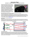
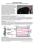
The Advanced CT Laser Collimator samples the entire optical system (primary, secondary mirror, and the eyepiece axial
position) with a simulated large aperture flat-wavefront light source generated by three parallel lasers positioned behind the
target plate. The target plate provides a clear view of the optics’ alignment condition when the three lasers are reflected back on
the target (FIG. 1). It is extremely critical that the lasers are pointed square-on (co-aligned) to the primary mirror for an accurate
reading. It is just like looking at a distant star and centering the star in the eyepiece field of view during a star test, except the
star is only about 3 feet in front of the telescope.
Advanced CT Laser Collimator User’s Manual (v8), page 1 of 7
To ensure accurate aiming, you use the diffused crosshair projected from the center of the collimator as a guide to optically
center aim the primary mirror back to the center of the collimator (FIG. 2A), and center aim the return crosshair reflected from
the primary mirror to square up the collimator aiming (FIG. 2B). Please expect to spend most time on these aiming adjustments.
Be patient and careful; the results will be well worth the trouble!
How to Adjust Collimation on Your Scope:
You can collimate your telescope at almost any position (e.g. telescope 20 deg. up) as long as
both the collimator and the telescope point square at each other. Once the lasers and
telescope are co-aligned, adjust the telescope's three secondary alignment screws carefully by
small amounts to move the three projected laser dots to the same bull's eye circle on the
collimator's target.
Process Flow Chart:
1. Set collimator distance
2. Install reflector in the telescope's visual back (2-inch or 1.25-inch as appropriate).
3. Aim telescope at the collimator (FIG. 2A)
4. Aim collimator at the telescope (FIG. 2B)
5. Adjust secondary to move the three laser spots onto the same circle on the target.
Package Content:
1 x Premium Soft Carrying Case
1 x Advanced CT Laser Collimator
1 x SCA Reflector Mirror (1.25” or 2”)
1 x 3V, CR123 Lithium Battery
1 x Users Manual (in cover pocket)
Advanced CT Laser Collimator User’s Manual (v8), page 2 of 7
1.0. Setting Up the Laser Collimator on the Tripod
1.1. Where to setup the telescope and the collimator
Position both collimator and the telescope on solid ground (no carpeted, wooden floor, or other surface that will flex or vibrate).
Both telescope and collimator must be on the (same) ground floor.
1.2. Setup the collimator on the tripod
a). Attach the fine-adjuster to your tripod using the tripod's 1/4-20 bolt.
b). Attach the laser collimator to the recommended fine adjustment stage
using the threaded knob on the fine-adjuster and the ¼-20 screw hole
on the bottom of the collimator.
c). Lock the collimator firmly in place with the lock-knob on the fineadjuster's 1/4-20 bolt.
2.0. Getting Familiar with the HOTECH Advance CT Collimator
2.1. Installing the battery
Unthread the battery compartment cap and insert the included CR123 lithium battery with the
positive side up (tip side up) and replace the battery cap.
2.2. Switching the laser to the proper mode
Position the collimator on a tripod about 4 feet from a white wall with the target side facing the
wall. Rotate the rotary knob on the top right corner of the collimator to activate different laser
modes. You will see the projected laser patterns on the wall at various positions.
Mode 0: Unit off.
Mode 1: Crosshair laser ON.
Mode 2: Crosshair laser and three alignment lasers ON.
Mode 3: Crosshair laser, three alignment lasers, and target backlight ON for night use.
Other modes:
DT: Three alignment lasers ON.
BL: Backlight ON.
1L: Crosshair laser and backlight ON.
CL: Three alignment lasers and backlight ON.
Please use the recommended mode in each procedure for best result.
2.3. Rough adjustment
Switch the laser to Mode 2, lift the tripod and move the collimator with the tripod to various
distances from the wall to see how the crosshair expands and contracts in size at different
distances.
2.4. Fine adjustment stage adjustment
Place the tripod with collimator back on the ground. Adjust the fine-adjustment stage as follows:
Vertical Adjustment:
- The large knob on right is for rough adjustment in the vertical direction. Loosen the large knob
and level the laser before continuing.
- The forward small knob is for fine adjustment in the vertical (up/down) direction. The large knob
must be locked in order to make to use this fine adjustment.
Horizontal Adjustment:
- The left side small knob is for fine adjustment in the horizontal (left/right) direction.
Advanced CT Laser Collimator User’s Manual (v8), page 3 of 7
3.0. Installing the Reflector Mirror:
3.1. Adapting the Retro Reflector Mirror on your focuser
If the telescope is to be used mostly for visual observation, it's a good idea to collimate with your star
diagonal in place. Please note that a poor quality diagonal, one with a misadjusted mirror, may
cause collimation problems. However, if photography or CCD imaging is planned, it is best to insert
the SCT mirror directly into the telescope's visual back. You will first, of course, need to thread your
visual back onto the telescope's rear port. Use either a 1.25-inch or 2-inch visual back depending on
the size of the nose piece mirror you purchased.
4.0. Positioning the Laser Collimator at the Proper Distance
The distance between the laser collimator and your
telescope varies depending on the diameter and focal length
of your telescope. In general, the greater the distance from
the telescope, the higher accuracy you will achieve. In
practice, any distance beyond the focal distance will be
sufficient. In this procedure, we will identify the best
collimating distance for the telescope.
4.1. Determine the distance between the laser collimator and your telescope
a). Position the collimator one tube length's distance in front of the telescope with
the target display facing the telescope (photo above).
b). Switch the collimator to Mode 1 (crosshair laser only).
c). Roughly aim the crosshair toward the telescope.
d). Experiment with the proper distance by lifting the tripod and collimator and
moving the collimator slowly toward and away from the telescope while keeping
the reflected crosshair on the target plate. Don’t worry about getting the
crosshair perfectly centered on the target at this point. You will see how the
crosshair contract and expands in size on the target plate in relation to the
distance adjustments.
e). Move the collimator to the distance where the crosshair is its smallest. This is
the back focal point of the primary mirror. Now, begin to move the target
towards the telescope until the crosshair expands to the size of the first ring.
f). Firmly position the tripod at this distance. This will be your collimating distance.
5.0. Achieving Co-Alignment on the Collimator and Your Telescope
This is the critical stage where you must co-align the collimator and your telescope for an accurate reading of your optics
alignment. DO NOT use the center of the secondary mirror assembly as a crosshair centering reference since the secondary
mirror might not be perfectly centered on the corrector plate. Referencing the center of the secondary as the pointing axis does
not mean the primary is also on the axis. You can use it as a quick gross aiming, but not for final aiming adjustment.
5.1. Center Aim your telescope to the collimator
Using a single-point light source emitting from the center of the collimator, the telescope can optically reference the reflected
light and aim back to the source. The primary mirror reflects a filled cone-shaped beam and projects onto the collimator’s
target plate as a donut shape beam (secondary mirror shadow in the center). Reference your adjustment only on the outer
diameter of the donut light beam to an equal-sized printed ring on the target. This technique will optically center aim the
telescope to the collimator.
a). Place the provided diffuser (matte-finish tape) in front of the center crosshair laser to diffuse the laser.
b). Use the telescope’s fine adjustment knob or its hand control to center aim the donut light beam to an equal or similar-sized
ring on the target.
c). Line up one axis at a time, up/down or left/right, unless you are very familiar with your telescope aiming control.
For example, move the telescope up/down adjustment to see where the donut light beam moves, and try to make just the
top and bottom of the donut have the equal distance to one of the ring on the target.
Then adjust left/right controls of the telescope to see where the donut light beam moves, and try to make just the left and
right side of the donut have the equal distance to the same ring on the target.
d). Iterate step (c) to close in the donut on the same ring.
Advanced CT Laser Collimator User’s Manual (v8), page 4 of 7
Donut is off from ring 1
Donut is centered
Note: If the diffused light is too dim to see, you may remove the diffuser and use the outer
edge of the crosshair line as the same referencing technique as the donut outer rim to line
up with the equal-sized ring on the target. Ignore the position of the crosshair line to the
printed target cross in this step.
For example, when centering the left/right position of the horizontal outer edge laser line,
ignore the vertical crosshair line offset position to the vertical printed line on the target plate.
Only try to bring the left and right outer edge of the projecting horizontal laser line to equal
distance on the ring during this task. See photo illustration.
5.2. Aim collimator square to the telescope
After the telescope is initially center aimed at the collimator in step 5.1, the collimator will also requires to pointing back at the
same origin to complete the co-alignment. In this step, you will adjust the aiming of the collimator by referencing the projecting
crosshair to the printed cross on the target.
a). Remove the diffuser to see the projecting crosshair.
b). Use the fine adjustment knob on the fine adjustment stage to refine the collimator aiming to line up with the printed cross
on the target plate.
c). Again, line up one axis at a time. Start with up/down adjustment, then left/right adjustment.
d). Place the diffuser back on the center laser to see if the donut light beam is still centered. If not, repeat step 5.1.
Advanced CT Laser Collimator User’s Manual (v8), page 5 of 7
5.3. Co-alignment confirmation
Continue to repeat the procedures in step 5, adjusting telescope and collimator until the donut and the crosshair are all
centered on the printed target. When you achieve this, it means both the telescope and the collimator are pointing square at
each other; for all intents and purposes, it's as if the telescope were pointed at a distant star. Lock your telescope and you are
ready to diagnose your optics.
6.0. How to Read the Diagnostic Result on the Collimator
With the telescope and collimator properly positioned in Step 5, the collimator can accurately reveal collimation errors in the
telescope’s optical system by means of the center deviation of three returning laser dots on the target plate.
6.1. Locate the three laser dots
a). Switch to Mode 2 or Mode 3 (three lasers and the crosshair, or Mode 3 with backlight).
b). Verify that the crosshair is still center-pointed on both the target plate and the Alignment Tabs (or internal screws in the
case of a Meade scope).
c). Note the three laser dots on the target plate.
d). If the three laser dots are visible on the target plate, go to step 8 to collimate the telescope.
e). If the three laser dots are not visible or are only partially visible on the target plate, please continue 6.2 and/or 6.3.
6.2. The SCA Reflector is not properly adapted
a). The SCA Reflector reflects the axial alignment of your visual back (or focuser drawtube with some types of telescopes).
You must install the SCA Reflector correctly (square in the visual back or drawtube). This axial position of the visual back
or drawtube affects the alignment of the entire optical system (telescope). Please refer to step 3 for proper SCA Reflector
installation.
b). If you have verified the SCA mirror is correctly installed, but the three laser spots are still completely or partially invisible,
continue to the next step, otherwise go to step 7.
6.3. The SCA Reflector is not positioned at the focal because the scope's focus is out of normal visual range
a). This can happen if the telescope was last focused with a diagonal in place (and it is not installed now), or a focal reducer
was in the optical train the last time the telescope was focused. The focal plane is too far out, and is not at the normal
visual position it would be in if the telescope were focused without a diagonal or focal reducer. If you do not want to use
the diagonal during CT collimation, you will need to adjust the telescope's focus. Continue to step b).
b). Adjust the focus to bring at least two laser dots into the full view on the target plate. Adjust the focus in one direction first
to see if any of the laser dots are moving toward the center direction of the target. If the laser(s) is moving or expanding
away from the center of the target, reverse the focusing direction to bring at least two laser dots into the full view of the
target plate. Go to step 7 to collimate your telescope.
6.4. Your telescope is grossly out of alignment
When your telescope is grossly out of alignment, the laser dots may be completely out of the target screen. If you believe this
to be the case, begin the collimation process anyway and see if you can bring the three laser dots into the target screen. An
excellent check for a grossly miscollimated scope is observing the reflections of the telescope mirrors by looking directly down
the tube. You will have to move the scope in azimuth to do so, of course. Turn off the laser before proceeding. Proceed to step
7.0.
7.0. Collimating the Telescope
The objective of this step is to bring the three laser dots onto the same ring on the CT collimator's target. You will need to
constantly check telescope and collimator positioning during the adjustment process to make sure proper aiming is maintained.
Here are few simple precautions to follow while adjusting the secondary mirror collimation adjustment screws located on the
secondary mirror assembly.
a. Never touch the central screw which holds the secondary mirror (usually only older SCTs will have this central screw).
b. The three screws must be turned in by very small amounts. No screw being over-tightened or totally unscrewed. ALWAYS
collimate by tightening screws ONLY. Only when a screw is snug should you loosen the opposite screw(s) to continue
moving the original screw in the proper direction. If collimation screws are loose, collimation will not be maintained for long!
c. As you adjust the collimation screws, observe the laser spot positions on the collimator to determine which screw(s) to turn,
and by how much.
7.1. Collimate your telescope
a). Adjust the alignment screws to bring the three reflected laser dots onto the same ring on the target.
b). If you cannot bring all three laser dots onto the target same target ring because the dots are too far apart, adjust the focus
to merge the three laser dots closer together.
c). Check for proper aiming of the collimator and the telescope in step 5.
The telescope might shift in position if you apply too much pressure during secondary mirror adjustment. You must double
check whether you have nudged the telescope pointing out of co-alignment.
d). Iterate step 7.1 until both the three laser dots are on the same track on the target and the collimator and telescope are still
co-aligned.
Advanced CT Laser Collimator User’s Manual (v8), page 6 of 7
8.0. Verifying and Fine Tuning Collimation
9.1. Star test to verify the adjustment
a). On your first observing session, star test the telescope to verify the adjustments.
The Advanced CT Laser Collimator should bring excellent collimation to your telescope. Minor adjustment might be
required due to temperature variation during a long observing session.
b). Choose a medium bright star--Polaris is good in the Northern Hemisphere. Defocus the scope a little, just until diffraction
rings are seen. The star should look like a little bull’s eye.
Carefully center the star and observe the diffraction rings. If they are concentric, collimation is good. If they are "squashed"
on one side, collimation requires further adjustment.
9.0. Possible Scenarios where the Laser Collimation Does Not Agree with Star Collimation
9.1. Both the collimator and the telescope were not co-aligned during adjustment
It is possible that during collimation (step 7), the co-alignment of the collimator and the telescope was slightly off causing an
incorrect diagnosis. It is very critical to ensure both the collimator and the telescope are co-aligned.
Do not adjust the collimation screws. Go to step 5 to verify the co-alignment of the collimator and the telescope and check if
three laser dots still fall on the same track. If both conditions are met, your optical system is in good condition meaning they’re
all lined up well on the same optical axis. If not, continue to the next step.
9.2. The "mirror flop" or "focus shift" the SCT primary mirror focusing mechanism is causing the miscollimation
Due to machining tolerances on the primary mirror and improper greasing on the baffle, some telescopes exhibit more mirrorflop then others. A slight loose tolerance will cause major axial alignment deviation. The Advanced CT Laser Collimator is
sensitive enough to pick up any deviation in step 5. Prior to adjusting the secondary alignment screws, observe the shifting
position of the three laser dots on the target by making two full turns clockwise of the focus knob, then reverse half turn. The
shifting of the laser dots during the reverse turn tells how much focus shift is present in the telescope.
If the displacement is more than 2 tracks distance, we recommend a rear cell Crayford focuser to the telescope (these are
available from many sources) for focusing adjustment, leaving the built-in focus mechanism untouched.
9.3. The eyepiece drawtube or visual back is not square to your primary mirror
We recommend replacing a poor visual back with a higher quality model (2-inch backs are generally better in quality than the
1.25-inch models furnished with SCTs). If the telescope uses a rear-cell focuser, it's possible to replace a poorly aligned one
with new higher grade eyepiece drawtube or a focuser that has tip/tilt adjustment to correct the axial error. For example, a
MoonLite CS model, or special modified focuser available from our website. Please email or call us for availability.
Advanced CT Laser Collimator User’s Manual (v8), page 7 of 7