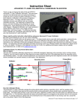
1
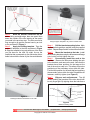
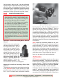
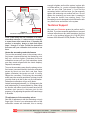
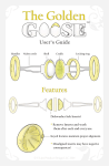
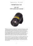
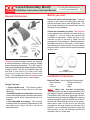
Curved Secondary Mount
Installation Instructions and User Manual
HOLDER
ASSEMBLY
ARCH
ASSEMBLY
#6 SCREWS
& FLANGE
NUTS
For solid tube telescopes up
to 15.0” inside diameter.
Before you start
General Information
COLLIMATION
ADJUSTMENT TOOL
& 3/16” DRILL BIT
MOUNTING
BRACKETS
Rev. 2/13
#8 SCREWS
& FLANGE
NUTS
Remove all optics from the telescope. To prevent
damage to your optics from falling parts and tools,
remove the primary mirror from the telescope. The
mirror holder should also be removed from the arch
assembly during installation.
Choose the orientation you want. The Protostar
curved support can be oriented in two ways as shown
in Figure 1. In most cases the top-mounted
orientation is preferable. When the arch is topmounted, no part of the arch is visible from the
vantage point of the focal plane. (Reflected light from
the support structure is eliminated.) In some cases,
other accessories (finder scopes, etc.) may interfere
with this location, so the bottom-mounted orientation
must be used.
SPACER
WASHERS
Kit Contents
Protostar curved secondary mounts are designed
to eliminate diffraction spikes by removing straight
edges obstructing the aperture. The 180º angle of
bend symmetrically spreads diffracted light rendering
it nearly invisible. The thin arch material (about 0.6
mm thick in most places) and short path length
produces the lowest total diffraction of any curved
design. (The total diffraction for the Protostar curved
mount is about the same as our 4-vane spider.)
Design Features:
¤ Tapered-width arch. The efficient doublecantilever design keeps the arch thin and
lightweight.
¤ Laminated metal arch construction. Larger arch
sizes are laminated sheets of stainless steel, which
increases rigidity while keeping thickness to a
minimum.
¤ Fully adjustable arch design. The mounting
brackets permit fine positioning adjustments of the
secondary mirror within the tube, as well as
secondary offset.
TOP-MOUNTED
ORIENTATION
BOTTOM-MOUNTED
ORIENTATION
Figure 1
Arch orientation options.
Installation Instructions
Required Tools. You will need the following tools:
- flat screwdriver
- Phillips screwdriver
- ruler
- pencil
- scissors
- tape
Step 1
Mark the bracket centerlines.
Temporarily attach the two mounting brackets to the
arch support using the supplied #6 screws and nuts.
The fasteners only need to be finger-tight. With the
bracket feet facing outward (see Figure 2), compress
the arch enough to make the bracket feet sit flat on
the tube wall. While holding the arch in this position,
make pencil marks on the end of the tube that
correspond to the small notches on the ends of the
brackets. It is not important to position the arch with
high precision, as you will accurately position the
secondary mirror in a later step.
MAKE PENCIL MARKS ON
THE END OF THE TUBE
WHERE THE BRACKET
NOTCHES ARE
Figure 2
ALIGN THE APPROPRIATE
LINE FOR YOUR SECONDARY
HOLDER SIZE WITH THE
CENTER OF YOUR FOCUSER
Marking the bracket centerlines
Step 2
Mark the bracket centerlines on the
tube. Using a straight edge, draw two pencil lines
down the outside of the tube starting at the marks
you made in the previous step. The lines need to be
long enough to go past the focuser base by an inch
or two as shown in Figure 3.
Step 3
Apply the drilling template. Tape the
paper drill template to the tube as shown in Figure
4. Align the template’s long axis with one of the lines
you just drew on the tube. By sight, line up the
centerline that corresponds to your secondary mirror
holder’s size with the center of your focuser drawtube.
Figure 4
Using the paper template to lay out the bracket holes.
Step 4
Drill the bracket mounting holes. Mark
the bracket hole positions, and drill using the supplied
drill bit. Repeat Steps 3 and 4 for the second bracket.
Step 5
Mount the brackets to the tube. Install
the mounting brackets using the #8 screws and flange
nuts, but do not fully tighten the nuts.
Step 6
Permanently install the arch to the
brackets. Remove the #6 screws holding the arch
to the brackets, and remove the arch. Note that the
brackets have three positions for the tangs at the
feet of the arch to snap in to. This allows for precise
positioning of the secondary mirror within the tube.
Find the best position for the arch that best positions
the secondary mirror within the tube. Reinstall the #6
fasteners, and fully tighten (see Figure 5).
Step 7
Edge-on arch adjustments. The #8
screws holding the brackets to the tube should still
be only finger tight. By sighting down the tube from a
PARALLEL PENCIL LINES
#6 FLANGE
NUT
#8 FLANGE
NUT
#6-32 SCREW
(BLACK)
BRACKET
#8-32 SCREW
Figure 3
TUBE WALL
Drawing the bracket centerlines on the tube.
Figure 5
Bracket mounting detail.
Protostar P.O. Box 448 Worthington, Ohio 43085
(614)-855-5341
Copyright © 1996-2013 Protostar
www.fpi-protostar.com
few feet away, check to see if the arch silhouette
appears edge-on. Make adjustments by twisting each
side of the arch until it appears the thinnest. (One of
the bracket holes is elongated to permit the bracket
to rotate.) When you are satisfied with the
appearance, tighten the bracket mounting screws.
Step 8
PLASTIC
SPACERS
Install the Secondary Mirror.
SILICONE
ADHESIVE
DOLLOPS
Important Note: If your secondary mirror is the
same size as the holder, it can be installed using
the metal shroud. In some cases, mounting the
mirror with an adhesive will be necessary:
(1) Our 0.75” and 1.00” holders are not supplied
with a shroud, so the glue method is used.
(2) Many imported secondary mirrors are not
the size of our holders, so gluing is required.
(3) Most secondary mirrors are from glass
castings and frequently slightly oversized. This
results in an interference fit with the metal shroud
which will optically distort the mirror. If your mirror
doesn’t seem to fit inside the shroud properly,
you should glue it in place. (Protostar mirrors are
CNC-machined to the correct size to prevent this
problem.)
Method #1: Install the Secondary Mirror With the
Shroud
Lay the foam mirror pad (paper
side down) and mirror in place on
the diagonal head face. Slip the
shroud onto the diagonal holder,
and loosely install the shroud
retaining screws. Position the
shroud onto the mirror until the
tabs lightly contact the mirror
surface. Do not push the
shroud too tightly against the
Figure 6
mirror, or you may deform the Mirror mounted
with shroud.
optical surface. Tighten the
shroud retaining screws. The
final installation should look like Figure 6.
Figure 7
Spacer and adhesive layout.
for this purpose.) Glue the three plastic spacers to
the holder near the edge as in Figure 7. After the
spacers are in place, glue the secondary mirror on.
Use silicone adhesive only. These are commonly
available from hardware stores (GE Silicone II®, Dow
Corning 733®, Devcon® Silicone Rubber, etc.). It’s
best to use a fresh tube, as there is a catalytic
component that evaporates with time. Make sure both
the mirror and holder face are clean and oil-free. Let
the adhesive cure for 24 hours in a room temperature
environment.
Step 9 Install the secondary holder to the arch.
Turn the hub collimation screws clockwise until they
protrude by about 1/8” (2 mm). Insert the secondary
holder into the hub on the arch, and visually ensure
that the three collimation screws are engaged into
the dimples on the clutch disk. The dimples prevent
the mirror holder from rotating when you turn the
collimation screws. Finger tighten the stem nut.
Now, you are ready for the initial collimation...
Collimation
Method #2: Install the Secondary Mirror With
Adhesive
All Protostar secondary mounts use the same
principal for collimation. The stem of the secondary
holder needs to be slightly stretched in order to hold
proper collimation. Tension in the stem is created by
tightening the tensioning nut as shown in Figure 8,
or by turning the collimation screws clockwise.
The secondary mirror can be glued directly to the face
of the Protostar holder as long as there is a small
gap left between the back of the mirror and the holder
face. (Your kit includes three small spacer washers
Collimation should always be done in the following
order; 1) center the secondary mirror under the
focuser using a sight tube, 2) tilt adjustment of the
secondary mirror, and 3) tilt adjustment of the primary
Protostar P.O. Box 448 Worthington, Ohio 43085
(614)-855-5341
Copyright © 1996-2013 Protostar
www.fpi-protostar.com
TENSIONING
NUT
Tension in
the stem
causes...
SEMI-RIGID STEM
COLLIMATING
SET SCREWS
CLUTCH
DIMPLES
enough to tighten and lock the system in place with
no further action (i.e., you do not need to tighten the
main nut as a final “lock down”). If you find the
secondary holder is still too loose, you can manually
tighten the tensioning nut another half turn. Do not
tighten the tensioning nut more than is needed to
just keep the holder from rotating freely. The
secondary mount is designed to hold collimation with
very little friction and tension in the system.
Technical Support
HUB
... clutch
friction here.
Figure 8
Functional components of a Protostar mount.
mirror. When doing the first collimation of a newlyassembled telescope, it’s almost always necessary
to repeat these steps several times. If repeating the
process is necessary, always go back and repeat
steps 1 through 3 in order. Consult the instructions
that came with your collimation tools on how to use
them.
We want your Protostar product to perform well in
the field. If you have a special application not covered
in these instructions or any other questions, feel free
to call us for technical support at (614)-855-5341
between 9:00 AM and 5:00 PM (Eastern Time Zone).
Center the secondary under the focuser
To move the secondary closer to the primary mirror,
first loosen (counterclockwise) the tensioning nut a
half turn, and then tighten (clockwise) the three
collimation screws until you feel resistance (make
sure they remain aligned with the clutch dimples).
Repeat as necessary.
To move the secondary away from the primary mirror,
first loosen (counterclockwise) the three collimation
screws by about one turn each, and then finger
tighten (clockwise) the tension nut until it is snug.
Repeat as necessary. Positioning the secondary
axially may take several repetitions, but keep in mind
you only need to do this for the very first collimation.
Subsequent collimation will go much faster.
Lateral centering adjustments (i.e., 90-degrees to the
axial adjustments) is accomplished by either tilting
the focuser with shims (some focusers have built-in
miniature jack screws in the base just for this
purpose), or by adjusting the position of the arch tangs
in brackets.
Tilt adjustment of the secondary mirror
Start the tilt adjustment with the tensioning nut only
finger tight. If most of your subsequent turns of the
collimation screws are clockwise, this us usually
Protostar P.O. Box 448 Worthington, Ohio 43085
(614)-855-5341
Copyright © 1996-2013 Protostar
www.fpi-protostar.com