1
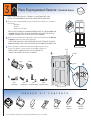
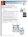
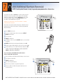
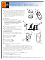
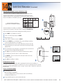
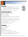
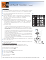
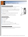
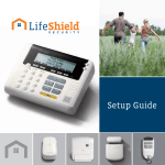
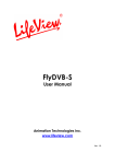
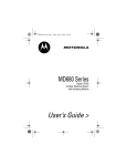
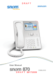
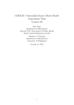
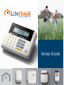
Setup Guide Welcome to LifeShield® Thank you for choosing LifeShield as your home security system. We take the safety of your home and family very seriously, and we are committed to giving you a fantastic customer experience. LifeShield was started as a way for consumers to have state-of-the-art home protection at an affordable cost. Today, we’re one of the fastest-growing security companies in the industry. At LifeShield, we pride ourselves on always being technologically ahead-of-the-curve. In fact, we were one of the first companies to offer free apps for every mobile platform. Now with LifeView™, our full-featured mobile interface, we’ve put complete control of your security system in your hands. You won’t find anything like it at any other security company. LifeView allows you to instantly arm and disarm your system, change your system settings, store video or still images from your security camera, find out your home’s current safety grade, and so much more. We encourage you to log in to LifeView as soon as you get your system set up, so you can start exploring these and other amazing, user-friendly features. This guide will walk you through the easy set up of your LifeShield system. We’ve already customized and tuned your system to your specifications, so everything should be ready to go when you open the box. All you need to do is call to activate your system: 888-387-8521. Also, we urge you to visit customers.lifeshield.com to learn more about your system. As soon as you’re finished setting up your system, it’s time to register with LifeView. Again, thank you for becoming a LifeShield customer. We will continue to do everything we can to make sure you, your home and your family are safe. Sincerely, MASTER CODE Mike Hagan President & CEO LifeShield, Inc. Louis Stilp Founder LifeShield, Inc. REFFERAL CODE 1 Component Placement Suggestions The LifeShield home security system you are about to set up is wireless. To maximize wireless coverage, plan to place the components throughout your home. Ideally, these components will be in different rooms on interior walls. A key consideration is making sure that all Sensors are within approximately 30 feet of one or more of the main components (base/cellular gateway, console). NOW IS A GOOD TIME TO PLAN YOUR COMPONENT PLACEMENT IMPORTANT: FOLLOW STEPS IN EXACT ORDER. DON’T SKIP AHEAD. BASE C E L L U L A R G AT E W AY SENSOR SENSOR CONSOLE SENSOR SYSTEM COMPONENTS Included with both KITS Home Essential KIT and Home Essential KIT–Cellular Ready BASE Home Essential Kit ONLY The Base connects your LifeShield system and the monitoring center via the Internet. Put the Base near your Internet modem/ router and near a wall outlet. Keychain Remote OR CELLULAR GATEWAY Home Essential KIT– Cellular Ready ONLY The Cellular Gateway connects your LifeShield system and the monitoring center via cellular network. console sensor/magnet Put the Cellular Gateway near an outside wall outlet on a high floor in your home. 2 1A If you ordered the Home Essential Kit start here, then proceed to Step 2. Connect Base (Home Essential Kit) Modem/Router C Remove the stand by sliding the Table Stand downward from the main body of the Base Insert the battery, then replace the Table Stand by sliding upward onto the main body of the Base E Ethernet Cable D C + (Optional) Phone Cord D Insert the power adapter, plug fully into the jack on the back of the Base. Then plug the power adapter into the wall outlet. E Connect the Ethernet Cable between an available port on your router and the back of the Base F Continue to Step 2 B Base Back View Table Stand Optional: If you connect a phone cord from the system Base to a telephone wall jack, you’ll have a back-up path for alarm communications if your Internet connection isn’t functioning. (ONLY APPLIES TO NON-VOIP PHONe services) 1B If you ordered the Home Essential - Cellular Ready Kit start here, then proceed to Step 2. Connect Cellular Gateway (Home Essential Kit-Cellular Ready) A For ideal reception, put the Cellular Gateway near an outside wall outlet on a high floor in your home B Remove the back cover of the Cellular Gateway C Plug the battery pack into the plug receptacle and insert the battery into the battery compartment D Replace the back cover E Plug the Cellular Gateway into the lower electrical outlet with the tab facing upward F Continue to Step 2 note: Green light on the cellular gateway is not a status light or signal strength indication 3 Cellular Gateway Back View C Battery Pack B E IMPORTANT: FOLLOW STEPS IN EXACT ORDER. DO NOT SKIP AHEAD. A Put the Base near your Modem/Router B 2 A Connect Console B Put the Console near a frequently used door, ideally in a different room than the Base/Cellular Gateway F *BUT NO MORE THAN 100 feet from the base/cellular gateway B Remove the battery compartment door C Plug the battery pack into the plug receptacle and insert the battery into the battery compartment D Snap on the battery compartment door E Connect power adapter to the back of the Console F Route the power adapter cord through the channel toward the top of the Console G Snap the table stand provided in the kit onto the back of the Console H Plug the power adapter into nearby electrical wall outlet that is not controlled by a switch E Battery Compartment Console Back View Power Cord H G Wall Mounting Table Stand To mount the Console to a wall, complete the following steps: A Select a wall location and use the mounting plate as a template for marking the wall for placement A NOTE: To mount the Console onto an existing telephone wall plate (not included) begin at Step d) B Drill 3/16” holes and insert drywall anchors (provided) into the holes C Screw the mounting screws into the anchors leaving the screws heads exposed approximately 3/8” (may require adjustment to achieve a tight fit) D Connect power adapter to the Console E Route the power adapter cord through the channel of the wall mounting plate F Slide the Console with mounting plate onto the wall screws or phone mounting plate G Plug the power adapter into nearby electrical wall outlet that is not controlled by a switch Mark Spot On The Wall Optional: Connect to the telephone line here (not included) Your Console has been preprogrammed with your system. No additional steps are necessary. 4 3 Place Preprogammed Sensors—Standard Sensor Note: If you intend to use a sensor in a location other than where it is programmed to be placed, please see the next page Double-Hung Window A There are up to 3 preprogrammed sensors that have been added. You only have to place them:* • Main Door • 2nd Door • Window 1 (if included) *Note: These 3 sensors have unquie properites built in. The main door and 2nd Door have an entry delay of 30 seconds, and an exit delay of 60 seconds. Window 1 has an entry delay of 0 seconds B Once you have determined the appropriate location and orientation for the Bracket and Magnet, attach them with double-sided tape *NOTE: When possible, place the bracket on the stationary FRAME OF DOOR OR WINDOW, AND PLACE THE MAGNET ON THE DOOR OR WINDOW ITSELF C Various orientations between the Bracket and Magnet may be used as long as 3/4" distance is not exceeded.* See Example in Figures 1-4. *Note: Spacers in bottom tray may be used on the bracket or magnet to adjust alignment Window Mounting Magnet A 3/4" spacing B Bracket Magnet Bracket B C Figure 1. Level Orientation Figure 2. Angled Orientation Figure 3. Figure 4. Perpendicular Orientation Perpendicular Orientation Door Mounting S E N S O R Sensor 5 Bracket Magnet K I T C O N T E N T S Magnet Tape *If you would like change any of the preprogrammed sensors see Step 4 Bracket Tape Magnet Spacer (optional use) Bracket Spacer (optional use) 4 Change Preprogrammed Sensors or Add Additional Sensors—Standard Sensor To change preprogrammed sensors A Press MENU on Console B Scroll to Security Setup on the screen, press SELECT C Enter Master Code* (found in the front cover of this book) D Scroll to Sensors E SELECT sensor to be modified F Use menu to select and change sensor attributes To add additional sensors: A Remove the battery tab by squeezing and holding the metal spring clip where the REMOVE tab folds around battery. The battery will spring upward. Carefully remove the insulating tab from under the battery, then gently press the battery back into the spring clip. A For this step you will need your Console and Sensor: Using Console: B Press MENU C Scroll to Security Setup, press SELECT D Enter Master Code* (found in the front cover of this book) E Scroll to Sensors, press SELECT F On <Add New>, press SELECT G Scroll to the type of Sensor (Open/Close), press SELECT H Wait 5 seconds before clipping the Sensor into the Bracket. You will then have 30 seconds to complete the setup. I Clip the Sensor into the Bracket. The Console will beep when the system finds the Sensor. This may take a few seconds *If ‘SENSOR OUT OF RANGE’ is displayed, the sensor is too far from the closest Console, base, or cellular gateway Squeeze & Hold Metal Clip Menu B J Press OK K Edit Sensor Name (Optional. You can change the name now or at a later time) • To change the Sensor Name, press the DELETE key to remove the default name • Using the keys on your Console keypad, type in the desired name • Press OK when complete L Sensor Placement: Scroll to Door or Window. Press OK M Alarm Type: Scroll to Stay & Away, Away Only, or Convenience. Press OK. Scroll Buttons Ready To Arm Thu 2/8 11:48a PHNBK MENU CONNCT WEATHR ALERTS C Testing your Sensor: N With system disarmed, test your Sensor by opening the door or window. Correct setup will generate a chime sound. If you don’t hear, a chime sound, see troubleshooting in the User Manual. Adding additional Sensors: O Repeat steps A-N for additional Sensors *Note: W herever Master Code is shown Please use your unique Master Code FounD in the front cover of this book 6 5 Place Preprogammed Sensors—Micro Sensor Note: If you intend to use a sensor in a location other than where it is programmed to be placed, please see the next page IMPORTANT: LEAVE THE PINK BATTERY TAB IN PLACE – DO NOT REMOVE UNLESS INSTRUCTED TO DO SO. NEVER REMOVE THE ANTENNA! A There are up to 3 preprogrammed sensors that have been added. You only have to Double-Hung Window place them:* • Main Door • 2nd Door • Window 1 (if included) *NOTE: THESE 3 SENSORS HAVE UNIQUE PROPERTIES BUILT IN. THE MAIN DOOR AND 2ND DOOR HAVE AN ENTRY DELAY OF 30 SECONDS, AND AN EXIT DELAY OF 60 SECONDS. WINDOW 1 HAS AN ENTRY DELAY OF 0 SECONDS. B Various orientations between the Sensor and Magnet may be used as long as it is no more than 1/2” distance apart.* See Example in Figure at right. C Once you have determined the appropriate location and orientation for the Sensor and Magnet, remove the adhesive sticker and place in the desired location. NOTE: make sure the centering markers( located on the flat inner surface of both the Magnet and Sensor) match up Window Mounting WHEN POSSIBLE, PLACE THE SENSOR ON THE STATIONARY FRAME OF DOOR OR WINDOW, AND PLACE THE MAGNET ON THE DOOR OR WINDOW ITSELF If you desire a more thoroughly disguised antenna, you can apply a light glue or adhesive to attach it to the frame of your window or door. It is important to remember not to fold or conceal the antenna underneath the sensor. The antenna must be free and clear of the body of the sensor in order for it to function properly. D With the system disarmed, test your Sensor by opening the door or window. Correct setup will generate a chime sound. Magnet A 1/2" spacing Sensor Door Mounting 7 *If you would like change any of the preprogrammed sensors see Step 6 B 6 Change Preprogrammed Sensors or Add Additional Sensors—Micro Sensor IMPORTANT: LEAVE THE PINK BATTERY TAB IN PLACE – DO NOT REMOVE UNLESS INSTRUCTED TO DO SO. NEVER REMOVE THE ANTENNA! To change preprogrammed sensors A Press MENU on Console B Scroll to Security Setup on the screen, press SELECT C ENTER Master Code* (found in the front cover of this book) D SCROLL to Sensors E F G Menu B Scroll Buttons Ready To Arm Thu 2/8 11:48a PHNBK MENU CONNCT WEATHR ALERTS SELECT the Sensor to be modified C Select New Sensor Placement • SCROLL, then SELECT Door or Window • Press OK When prompted by the Console, pull the pink battery tab from sensor (DO NOT PULL THE ANTENNA) NOTE: If you have pulled the battery tab before this portion of the setup, see steps N-P H Edit the Sensor name • Press DELETE to remove the default name • Using the keys on your Console, type in the desired name • Press OK when complete I Select Sensor Placement using Console • SCROLL, then SELECT Door or Window • Press OK J Alarm Type: Scroll to Stay & Away, Away Only, or Convenience. Press OK K To complete your sensor registration, seperate the magent from the sensor, then place them back together. Your console will make an audible chime and your sensor will be added. t L Line up the sensor and the magnet in a closed position, then slightly separate from each other. Once they are separate, your Console will make an audible chime. This is how you know you have set up your sensor correctly M See Stage 5 for instructions on how to install your magnet and sensor to your doors and windows If you pulled out the battery tab before prompted to do so: N Gently open your sensor and repeat steps A-F NOTE: Make sure that there is space between the metal clip and the round battery while you perform steps A-F. Either put the battery tab back or put a piece of paper between the clip and the round battery. The clip and battery cannot make contact while being added. O When the console prompts you to pull the battery tab, remove the piece of paper or replaced battery tab (or press down on the metal clip) so that it makes direct contact with the circular battery. P Replace the back of the senor and proceed to the next portion of the set up (Step H) *Note: Wherever Master Code is shown Please use your unique Master Code FounD in the front cover of this book 8 7 Add Additional Keychain Remote(s) NOTE: Your Keychain Remote is ready to go and preprogrammed for a Master User If you have more than one Remote, you must create new User Codes before those keychains can be added. The LifeShield system can support up to 8 Users—1 Master User, who is able to change System Settings—and 7 Normal Users, who are only able to Arm and Disarm the system. Scroll Buttons Ready To Arm Thu 2/8 11:48a Menu PHNBK MENU CONNCT WEATHR ALERTS *For multiple keychains, you must create a unique user for each keychain User Codes can easily be added, changed or deleted from the system Console. Here are the steps to add a pregrogrammed Keychain Remote: A Press Menu on Console B Scroll to Security Setup on the screen, press Select C Enter Master Code* D Scroll to Users E Select <Add New> F It defaults to User 1; use the delete button to erase default username G Enter desired name using keypad numbers, press OK H Create a unique 4-digit arming code for this user, press OK I System will ask you to confirm <New User> add, press OK Keychain Remote *Note: If you have additional users to create Select <Add New> and repeat If you are ready to add additional keychain remotes please continue with steps below: J Press the Button under Back (which displays on the Screen) K Scroll down to Keychains L Select <Add New> M Press all 3 Keychain buttons N Select user you want to assign the Keychain to O Select to enable or disable the panic button based on your preferences Menu A Scroll Buttons Ready To Arm Thu 2/8 11:48a PHNBK MENU CONNCT WEATHR ALERTS B *Note: Wherever Master Code is shown Please use your unique Master Code FOUND IN THE FRONT COVER OF THIS BOOK 9 8 Place Preprogammed Motion Sensor Prepare Motion Sensor (if included) A B Battery A Separate the Front and Back Covers of the Motion Sensor by pressing the tab with your finger or the top of a pen (Figure A). Insert the battery. B Select the desired sensitivity. As shown in Figure B, place the jumper over both pins for Normal Sensitivity, or place the jumper over just one pin for High Sensitivity. In most cases, Normal Sensitivity is the recommended setting. This can always be changed later if your experience shows the Normal is not meeting your needs. Press nsi Se tivi h Hig rmal No ty Place Motion Sensor C Place the Motion Sensor following the location recommendations (check marked locations) shown in Figure C. Avoid the example locations marked with the “X” which are household areas that typically cause false alarms, such as heat, air conditioning, fans, or direct sunlight. The recommended mounting height is 7.5 feet for both coverage and pet immunity purposes. Sensitivity Jumper C D Apply the 3M adhesive tape in the locations shown in Figure D for corner mounting or wall mounting E The rounded end of the Motion Sensor that has the release tab is the bottom of the sensor, which should be closest to the floor when installed properly Add Additional Motion Sensors D A Seperate the front and back covers of the Motion Sensor by Top Tape For Corner Mount E pressing the tab with your finger or a pen. Remove the battery. B On the Handset or Console, press MENU C Scroll to Security Setup, press SELECT D Enter the Master Code* E Scroll to Sensors, press SELECT F Scroll to <Add New>, press SELECT Tape For Wall Mount G Scroll to Motion, press SELECT H Following the instructions displayed on the LCD screen: Bottom - Wait 5 seconds - If the display reads “Un-clip Sensor from Bracket”, insert the battery into the Motion Sensor - If the display reads “Insert Battery”, insert the battery into the Motion Sensor observing correct When the Motion Sensor has successfully been added you will hear 4 fast confirmation beeps from the LifeShield system. If there are no confirmation beeps, remove the battery from the Motion Sensor then re-insert the battery into the Motion Sensor to cause another power-up registration message to be sent. Once the Motion Sensor has been added to the LifeShield system: I Use the Edit feature to rename the device (if desired). Press DELETE to erase text and the keypad keys to type new text. J Press OK, then press BACK until the Main Menu is displayed K Re-attach the Front and Back Covers of the Motion Sensor *Note: Wherever Master Code is shown Please use your unique Master Code FounD in the front cover of this book 10 9 Add Fire Safety Sensor (AKA “Siren Detector”) (if included) The Fire Safety Sensor works with your existing hazard detectors (smoke/fire alarms, carbon monoxide detector, or both) to send a signal to the monitoring center whenever your hazard detector sounds. Mount the Fire Safety Sensor no more than 4” away from the targeted hazard detector. A Remove the Installation Template on the bottom of the Fire Safety Sensor box. Place next to the existing hazard detector (Figure B) so the large curved side of the template rests against the outer edge of the hazard detector. Using a pencil or pen, mark the location of the two screw hole openings in the template on the ceiling. These marks will be used as a mounting location reference B Turn the Fire Safety Sensor over and press the bracket release tab while gently pulling the bracket away from the device C Attach the Fire Safety Sensor Bracket to the ceiling using either double-sided tape or the provided screws and wall anchors. Be sure the arrow on the inside of the bracket faces the hazard detector. D Turn the Fire Safety Sensor over and locate the battery insulator tab by pulling it straight out. Discard the tab. B Existing Hazard Dectector Installation Template NOTE: AFTER REMOVING THE TAB, PRESS DOWN ON THE TOP OF THE BATTERY TO BE SURE IT HAS NOT BEEN DISLODGED E Align the Fire Safety Sensor with the bracket and snap it on Add Fire Safety Sensor Once the Fire Safety Sensor has been mounted, it must then be “added” to the LifeShield System. For this step you’ll need your Console: F Press MENU on Console G Scroll to Security Setup, press SELECT H Enter the Master Code* D E I Scroll to Sensors, press SELECT J Scroll to <Add New>, press SELECT K Scroll to Fire Safety Sensor, press SELECT L Following the instructions displayed on the Console. Wait 5 seconds, then press the button on the Fire Safety Sensor. Note: Once the Fire Safety Sensor is “found”, you’ll have to do an audio test to be sure if the siren from the target hazard detector can be detected by the Fire Safety Sensor M Following the instructions displayed on the Console, press the “test” button on the hazard detector until the Console displays “Fire Safety Sensor Added”, which indicates that the test has passed. If the test does not pass within 10 to 12 seconds of the siren sounding, the hazard detector may not meet the requirements described earlier and may need to be replaced. If the test fails, the LifeShield system will not permit the Fire Safety Sensor to be added. N Once the Fire Safety Sensor has been added to the LifeShield system, use the Edit feature to rename the device (optional) NOTE: Press DELETE to erase text and use the keypad keys to type in a new name. Once you are satisfied with the entered name, press OK. O Scroll down to select the type of hazard detector to which this Fire Safety Sensor will be associated (SMOKE/FIRE, CARBON MONOXIDE or BOTH) and press SELECT (NOTE: Not all smoke/carbon monoxide detectors are compatible with the Fire Safety Sensor. If the siren for your current smoke/carbon monoxide detector sounds for 30 seconds and there is no pause in the siren the Fire Safety Sensor should operate as intended) Important: the selection you make during this configuration step will determine the type of message that is sent to the monitoring center P 11 Press OK to return to the Main Menu *Note: W herever Master Code is shown Please use your unique Master Code FounD in the front cover of this book See the User Manual for more detailed instructions and information about testing the Fire Safety Sensor. 10 Add Outdoor Camera Model OC810 (if included) The OC810 is an Outdoor Camera with built-in Infrared LEDs for night vision To USE A First plug Ethernet cord into camera and router. Wait for Power LED to stay solid B On console select Menu > Cameras > Add New > AUTO SEARCH > YES C Once all cameras are found, press OK D Log in to LifeView and select Camera > Camera Settings > Edit A. Enter SSID or Network Name, wireless connection security type and password *Entries are case sensitive, spelling and spacing must be exact E Once Wifi* information has been saved wait 2 minutes before unplugging the power and then Ethernet F After 2 minutes, plug power back into camera and leave Ethernet unplugged. Once power light is solid the camera is wireless and ready for final placement. A *If the camera works while connected to the Ethernet but not wirelessly then the WiFi* information must be verified. Repeat To reset, insert paperclip into reset button (next to power connector) for at least 5 seconds and release NOTES Must be on same router as your LifeShield Base to setup. After wireless setup, plug into power where you like Setup WiFi using camera Settings in LifeView®, disconnect Ethernet cable, then remove and reconnect the power Setup alerts in LifeView to take pictures when sensors tigger Live video per session is 5 minutes Wifi antenna must be installed to use WiFi Use rubber cover for Ethernet plug If the camera works while connected to the Ethernet but not wirelessly then the WiFi information must be verified. Repeat step D if necessary. *Wireless, or WiFi, technology allows an electronic device to exchange data wirelessly (using radio waves) over a computer network Use rubber cover for power plug 12 11 Add Indoor Camera Model RC8221 (if included) The RC8221 is an indoor Camera with built-in Infrared LEDs for night vision To USE A First plug Ethernet cord into camera and router. Wait for Power LED to stay solid B On console select Menu > Cameras > Add New > AUTO SEARCH > YES C Once all cameras are found, press OK D Log in to LifeView and select Camera > Camera Settings > Edit A. Enter SSID or Network Name, wireless connection security type and password *Entries are case sensitive, spelling and spacing must be exact E Once Wifi* information has been saved wait 2 minutes before unplugging the power and then Ethernet F After 2 minutes, plug power back into camera and leave Ethernet unplugged. Once power light is solid the camera is wireless and ready for final placement. A *If the camera works while connected to the Ethernet but not wirelessly then the WiFi* information must be verified. Repeat POWER POWE DO NOT use the WPS Button, Micro SD Slot, or green wire connector NOTES Must be on same router as your LifeShield Base to setup. After wireless setup, plug into power where you like Setup WiFi using camera Settings in LifeView, disconnect Ethernet cable, then remove and reconnect the power Setup alerts in LifeView to take pictures when sensors tigger POWER POWE PRIVACY V RESET Live video per session is 5 minutes If the camera works while connected to the Ethernet but not wirelessly then the WiFi information must be verified. Repeat step D if necessary. WPS PRIVACY V POWER WPS NETWORK RESET POWER NETWORK *Wireless, or WiFi, technology allows an electronic device to exchange data wirelessly (using radio waves) over a computer network 13 To reset, insert paperclip into reset button (next to power connector) for at least 5 seconds and release 12 Add Handset (if included) Install the Handset and Charger Install Battery Pack A Open the Battery compartment B Insert the Battery plug into the two-pin jack, and insert the Battery C Install Battery Pack Add the beltclip Replace the Battery cover NOTE: Use only the LifeShield LS80 Battery Pack Adjust handset and beltclip - Attach Belt Clip - Snap the Belt Clip onto the sides of the Handset Connect the Charging Cradle - Connect the Charging Cradle power adapter to the bottom of the Charging Cradle and to the electrical wall outlet Charge the Handset Place the Handset in the Charging Cradle. When properly seated on the cradle, the amber light on the front of the cradle will be illuminated. NOTE: Immediately place the Handset in the Charging Cradle that came packed with the Handset. THE HANDSET MUST BE CHARGED FOR AT LEAST 30 MINUTES PRIOR TO ATTEMPTING ANY SECURITY SYSTEM INSTALLATION. IT MUST BE CHARGED FOR 2 HOURS BEFORE MAKING PHONE CALLS. NOTE: The phone system comes with various settings pre-defined from the factory. Should you want to change these settings, we suggest waiting until after you activate your system. These settings include ring tones, ring volume, distinctive ringing, display contrast, etc. Add the Handset to Your LifeShield System Follow these steps for adding an additional Handset to a LifeShield system. Handsets packed with kits are pre-registered and do not require these steps. After the initial installation of the LifeShield System, devices may be added to enhance access or performance The maximum number of devices that can be added to a LifeShield System is shown in the table to the right. After the Handset and Charger are installed, use a Handset or Console that is already registered on the System to add the new Handset. Add the Handset A On an Existing Handset or Console, use the SCROLL and SELECT buttons to navigate to GC or Handset (Menu/Security Setup/GCs or Handset/<Add New>) B Press the SELECT key to <Add New>. The system will begin searching for a new Handset. C On the new Handset, press the SEARCH key D The system display and audio signal will inform you the Handset is found E You will then be given the option to edit the default name F Use DELETE to erase the current name and replace with new text by using the keypad. *The system will allow a maximum of 8 Handset/Console of Grid Extender combinations. *Note: Wherever Master Code is shown Please use your unique Master Code FounD in the front cover of this book 14 13 Add Glassbreak Sensor (if included) Install Glassbreak Sensor A Remove the Glassbreak Sensor and related components from the box and physically install the device according to the manufacturer’s printed instructions NOTE: It is important to follow the manufacturer’s printed instructions regarding (a) connecting the batteries, (b) adjusting the sensitivity, (c) selecting the location and (d) mounting the device prior to moving on to the next step involving integration of this device with your LifeShield system. Please note that it is not necessary to “Enroll” the device at this time. B Mount the Glassbreak Sensor to a flat surface and close the front cover Add the Glassbreak Sensor to the LifeShield system NOTE: A LifeShield system (including a Base and at least one Handset or Console) must be installed before a Glassbreak Sensor can be added Starting with the Glassbreak Sensor mounted to a flat surface with the front cover closed: A On the Handset or Console, press MENU B Scroll to Security Setup, press SELECT and enter the Master Code* C Scroll to Sensors, press SELECT D Scroll to <Add New>, press SELECT E Scroll to Glassbreak, press SELECT F Following the instructions displayed on the LCD screen: NOTE: Wait 5 seconds then open the front cover of the Glassbreak Sensor (PRESS TAMPER FOR 1 SEC AND RELEASE). You will have 30 seconds to complete this step. When the Glassbreak Sensor has successfully been added you will hear 4 fast confirmation beeps from the LifeShield system If there are no confirmation beeps, check to make sure that the battery insulator tab has been removed and repeat the steps above Once the Glassbreak Sensor has been added to the LifeShield system: G Use the Edit feature to rename the device if desired (Press DELETE to erase text and the keypad keys to type new ones) H Press OK, then press BACK until the Main Menu is displayed I Shut the front cover of the Glassbreak Sensor Test the Glassbreak Sensor 15 A On the Handset or Console, press MENU B Scroll to Utilities, press SELECT C Scroll to Test, press SELECT D Enter your Master Code* E Select System Test F Press the SKIP soft key to skip the Siren Test G Press the OK soft key on next screen for Starting Comm Test H Scroll to the name of the Sensor that you would like to test, and press SELECT I Tap strongly on the front cover of the Glassbreak Sensor If the Glassbreak Sensor test is successful, the LCD screen will display “Sensor xxx Passed”. If these words do not appear, return to “Add the Glassbreak Sensor to the LifeShield System”. *Note: Wherever Master Code is shown Please use your unique Master Code FOUND IN THE FRONT COVER OF THIS BOOK 14 Add Grid Extender (if included) Add the Grid Extender to Your LifeShield System Follow these steps for adding an additional device to an existing system. After the initial installation of the LifeShield System, components may be added to enhance access or performance. The maximum number of devices that can be added to a LifeShield System are: A *The system will allow a maximum of 8 Handset/Console of Grid Extender combinations. * The system allow a maximum of 8 After the hardware is installed, use a Handset or Console that iswill currently or Extender Grid Extender combinations. registered on the System to follow the steps for Handset/Console adding the Grid * The system will allow a maximum of 8 Handset/Console or Grid Extender combinations. B Before installing have grid extender unplugged and battery removed A Press MENU on your Handset or Console B Scroll to Security Setup and press SELECT C Enter Master Code* D Scroll to GCs or Handsets and press SELECT E Press the SELECT key to <Add New>. The system will begin searching for the new Grid Extender you are adding. F Connect grid extender to power outlet (with battery still removed). On the Grid Extender, press and hold the center button until the green light rapidly flashes. G GX Found The following messages will appear on the Handset or Console when the Please wait system has found and added the Grid Extender H * The system will allow a maximum of 8 Handset/Console or Grid Extender combinations. G GX Found Please wait 60 Seconds Flashing Light 60 Seconds Press OK when you have been informed that the GX has been added CANCEL Add Button GX Added GX Found Please wait CANCEL 60 Seconds OK CANCEL OK GX Added GX Added F Determine The Location CANCELapart from the Console and Base. A Place the Grid Extender in a location that is spread GX Added second floor location is a great place to install this, if you choose. Having these devices spread throughout the home will maximize system coverage. A power outlet is required to operate the Grid Extender. Install The Grid Extender CANCEL CANCEL GXI Found You will then be given the option to edit the default name Please wait Use DELETE to erase the current name and replace with new text by 60 JSeconds using the keypad CANCEL K Press OK when editing is complete GX Found Please wait 60 Seconds CANCEL CANCEL OK OK GX Added A Install Battery Pack CANCEL OK Open the Battery compartment 1) Insert the Battery plug into the two-pin jack, and insert the Battery 2) Replace the Battery cover B Plug the Grid Extender into the electrical wall outlet *Note: Wherever Master Code is shown Please use your unique Master Code FounD in the front cover of this book 16 15 Add Smoke Sensor (if included) Install Smoke Sensor A Remove the Smoke Sensor and related components from the box and physically install the device according to the manufacturer’s printed instructions. A NOTE: It is important to follow the manufacturer’s printed instructions regarding placement of the device (location), installation (mounting) and battery activation (including removal of the battery tab insulator paper) prior to moving on to the next step involving integration of this device with your LifeShield System. B Once the mounting bracket is secured to the ceiling, attach the Smoke Sensor into it. Add the Smoke Sensor to the LifeShield System A On the Handset or Console, press MENU B Scroll to Security Setup, press SELECT and enter the Master Code* C Scroll to Sensors, press SELECT D Scroll to <Add New>, press SELECT E Scroll to Smoke Sensor, press SELECT F Following the instructions displayed on the LCD screen: Wait 5 seconds then detach the Smoke Sensor from the mounting bracket “Remove Detector from bracket”. You will have 30 seconds to complete this step. When the Smoke Sensor has successfully been added you will hear 4 fast confirmation beeps from the LifeShield system. If there are no confirmation beeps, check to make sure that the battery insulator tab has been removed, re-attach the Smoke Sensor to the mounting bracket and repeat the steps above Once the Smoke Sensor has been added to the LifeShield system: G Use the Edit feature to rename the device (if desired). (Press DELETE to erase text and the keypad keys to type new ones). H Press OK, then press BACK until the Main Menu is displayed I Re-attach the Smoke Sensor to the mounting bracket Test the Smoke Sensor A On the Handset or Console, press MENU B Scroll to Utilities, press SELECT C Scroll to Test, press SELECT D Enter your Master Code* E Select System Test F Press the SKIP soft key to skip the Siren Test G Press the OK soft key on next screen for Starting Comm Test H Scroll to the name of the Sensor that you would like to test, and press SELECT I On the Smoke Sensor, press the small Test button located on the front cover for at least 30 seconds If the Smoke Sensor test is successful, the LCD screen will display “Sensor xxx Passed”. If these words do not appear, return to “Add the Smoke Sensor to the LifeShield System”. 17 *Note: Wherever Master Code is shown Please use your unique Master Code FOUND IN THE FRONT COVER OF THIS BOOK 16 Add Water & Temperature Note: Do not re-attach cover until you have added this device to the LifeShield System (if included) Battery Setup The Sensor A Locate the Honeywell 5821 box (red and white) and remove the white wireless transmitter from the box B Using a flat object such as a screwdriver, pry off the top cover of the transmitter and set aside C Press down on the mounting plate bracket release tab to remove (slide off) the mounting plate. Place the mounting plate aside. D Reference the table at right to determine the desired sensing type (Hot Temp, Cold Temp, Warm Temp or Flood [water]). Using the tip of a paperclip (or similar object) push the white (sliding) buttons of the DIP switch into the configuration that corresponds to the desired sensing type E Follow the appropriate steps associated with the sensing type of the Sensor D a. Temperature Sensor (Hot, Warm or Cold) sensing: Locate the mounting bracket where it will be most suitable for Temperature Sensing (for example on a wall, ceiling, etc.). Using either the supplied screws or double-faced adhesive tape, secure the mounting bracket to a flat surface (wall or ceiling). b. Flood (water) sensing: i. Locate the water probe assembly (with wires attached as shown) and mount it near the “baseline” surface (ex. floor) using the supplied double-faced tape or suitable wall mounting screws (not supplied). It is recommended that the probe be mounted between 0 to 1/8” above the baseline surface ii. Loop the free end of the Water Probe wire through the back of the wireless transmitter (as shown in Figure ii) and connect the wire pair to the loop terminal block by inserting the wires (individually) into the loop terminals and tightening the screws ii iii. Determine the best location to install the mounting plate above the location where the Water Probe has been installed, being careful not to position it too high (beyond the length of the wires now connecting the water probe and wireless transmitter) iv. Using either the supplied screws or double-faced adhesive tape, secure the mounting bracket to a flat surface (wall or ceiling) F Install the CR123 battery (supplied) into the wireless transmitter noting the correct orientation of the positive (+) and negative (-) ends G Position the wireless transmitter over the mounting plate and slide the wireless transmitter securely into place (until it “clicks”) Add the Sensor to the LifeShield System Once the Temperature and Flood (Water) Sensor is installed it must be “added” to the LifeShield system in order to function. You will need a Handset (or Console) to add it. Enter the Security menu on the Handset (or Console) A On the Handset (or Console), press MENU B Scroll to Security Setup, press SELECT and enter the Master Code C Scroll to Sensors, press SELECT D Scroll to <Add New>, press SELECT E Scroll to Environmental, press SELECT (Continued on next page) *Note: Wherever Master Code is shown Please use your unique Master Code FOUND IN THE FRONT COVER OF THIS BOOK 18 16 Add Water & Temperature cont. Add the Sensor to the LifeShield System (Continued) F Following the instructions displayed on the Handset (or Console), wait 5 seconds, then press and release the red tamper switch button on the wireless transmitter (see Figure A). J Once the Sensor has been added to the LifeShield system: G Use the Edit feature to rename the device (optional). NOTE: Press DELETE to erase text and use the keypad keys to type in a new name. Once you are satisfied with the entered name, press OK. H Scroll down to select the type of condition to which this Sensor will be associated (Flood, Cold, Warm or Hot) and press SELECT I Press OK to return to the Main Menu J Position the top cover in place over the wireless transmitter and snap it into place, being careful not to pinch or cut the wires leading to the Water Probe (if the Sensor is set up for Flood detection) If the Sensor test is successful, the LCD screen will display “Sensor xxx Passed”. If these words do not appear, return to “Add the Sensor to the LifeShield System”. Note: Do not re-attach cover until you have added this device to the LifeShield System Battery Testing a Flood (Water) Sensor A On the Handset (or Console), Press MENU B Scroll to Utilities, press SELECT C Scroll to Test, press SELECT D Enter your Master Code E Select System Test F Press the SKIP soft key to skip the Siren Test G Press the OK soft key on next screen for Starting Comm Test H Scroll to the name of the Sensor that you would like to test, and press SELECT I Place the Water Probe directly into water (or alternately place a piece of wet cloth between the probe legs) and wait at least three (3) minutes Testing a Temperature (Hot, Cold, Warm) Sensor The temperature sensing aspects of the Honeywell Model 5821 can be tested in the same manner as above with the use of specialized equipment that is capable of increasing or lowering the ambient temperature in the environment surrounding the Sensor (as needed to result in activation) 19 *Note: Wherever Master Code is shown Please use your unique Master Code FOUND IN THE FRONT COVER OF THIS BOOK SETUP COMPLETE To complete the activation process please call 888-387-8521. Now that you’ve set up and activated your system, it’s time to find out how LifeShield can fit into your everyday life. You can access your security system from in any of 4 ways: your Console, Keychain Remote, LifeView web application or LifeView mobile applications. ARMING YOUR SYSTEM “Stay Arming”—Home During the Day Maybe you work at home, or you’re taking care of the kids during the day. This is the setting you want to use on your LifeShield system. By activating Stay Arming, the system will ignore certain Sensors, like the Motion Sensor and Sensors on interior doors. Arm the system using the STAY key. A silent Exit Delay and an audible Entry Delay is provided. You can arm your system using one of the 4 devices: Console, Keychain Remote, LifeView Web Application, and LifeView Mobile Applications. TO ARM Using the Console 1 . Press STAY on your Console and enter your Master Code* 2. The system is armed when the Exit Delay has expired Using the Keychain Remote 1 . Press and hold STAY on the Keychain Remote for 2 seconds 2. The system will respond with a light blink and beep letting you know the system is armed Using the LifeView Web Application 1 . Login to LifeView with your User Name and Password 2. Click Arm Stay Using the Mobile Applications 1 . Login to LifeView Application with your Username and Password 2. Click Stay 3. Enter Master Code* “Away Arming”—Leaving Your Home If you’re going to leave your home—even for a quick run to the store—or if no one is at home, arm the system using the AWAY key. It will provide an audible Exit Delay. The Exit Delay beep will increase in frequency during the last 10 seconds of arming. You can arm your system using one of the 4 devices: Console, Keychain Remote, LifeView Web Application, and LifeView Mobile Applications. TO ARM Using the Console 1. Press AWAY on your Console, and enter your Master Code* 2. The system is armed when the Exit Delay has expired Note: If a door doesn’t open and close during the exit delay, the system will automatically switch the arming mode to STAY Using the Keychain Remote 1. Press and hold AWAY on the Keychain Remote for 2 seconds 2. The system will respond with a light blink and beep, letting you know the system is armed Using the LifeView Web Application 1. Login to LifeView Application with your User Name and Password 2. Click Arm Away Using the LifeView Mobile Application 1. Login to LifeView with your Username and Password 2. Click Away 3. Enter Master Code* 20 *Note: Wherever Master Code is shown Please use your unique Master Code FOUND IN THE FRONT COVER OF THIS BOOK ARMING YOUR SYSTEM (CONTINUED) “Instant Arming”—Staying Home for the Evening When you and the family are in for the night—watching TV or going to bed—arm the system using the INSTANT key. You want to use this when you’re not expecting anyone to enter the house, and when you’re not planning on going out. With INSTANT arming, No Exit or Entry Delay is provided, and opening a door that’s armed will generate an immediate alarm. You can arm your system using one of the 3 devices: Console, LifeView Web Application, and LifeView Mobile Applications. TO ARM Using the Console 1. Press INSTANT on your Console, and enter your Master Code* Using the LifeView Web Application 1. Login to LifeView with your User Name and Password 2. Click Arm Instant Using the LifeView Mobile Applications 1. Login to LifeView with your Username and Password 2. Click Instant 3. Enter Master Code* Disarming Your System Use this whenever you want to cancel any alarm you’ve caused. You can disarm your system using one of the 4 devices: Console, Keychain Remote, LifeView Web Application, and LifeView Mobile Applications. TO DISARM Using the Console 1. Press CANCEL/OFF on your Console and enter your Master Code* Using the Keychain Remote 1. Press Cancel/OFF to disarm the system before entering. 2. The system will respond with a light blink and beep, letting you know the system is disarmed Using the LifeView Web Application 1. Login to LifeView with your User Name and Password 2. Click Disarm Using the LifeView Mobile Application 1. Login to LifeView Application with your Username and Password 2. Click Disarm 3. Enter Master Code* help Panicking Your System An alarm generated by pressing the PANIC button will send a message to the Alarm Monitoring Center to contact the authorities without making a call to you to verify the alarm. Do not attempt to test your system by using the Panic Button. Emergency Services will be dispatched. You can panic your system using one of the 2 devices: Console and Keychain Remote TO PANIC Using the Console 1. Press and hold PANIC for 2 seconds (if enabled) 2. Select Police, Fire, or Medical (if no selection is made, police will be default selection) Using the Keychain Remote 1. Press and hold STAY and AWAY at the same time for 2 seconds (if enabled and you’re near your home) *Note: Wherever Master Code is shown Please use your unique Master Code FOUND IN THE FRONT COVER OF THIS BOOK 21 RESPONDING TO AN ALARM 1 . PANIC - When you panic your system, local authorities will be dispatched to your monitored address automatically. There will be no phone call to verify the status of your alarm and the signal cannot be canceled. 2. BURGLARY & FIRE - In the event of an alarm the monitoring center will call to verify the status of the alarm a. The Primary Contact will be called first. If they do not answer the Secondary Contact will be called. b. If neither of the contacts can be reached then the monitoring center will automatically dispatch emergency services. c. If one of the Contacts is reached they will be asked to provide the Monitoring Password that you created during your initial setup of your account. This is NOT your Master Code which is located in your Quick Setup Guide. d. If an incorrect Monitoring Password is provided, the monitoring center will not inform you and will automatically dispatch the authorities. If the correct Monitoring Password is given, then the monitoring center will act as directed by the Contact. 3. WATER & TEMPERATURE - You will need to configure your system so that you will receive notifications when the sensor is triggered. For additional information regarding a trigged alarm please go to: lifeshield.com/customers/system-faqs Local Permit and Registration (if applicable) To activate the monitoring service for your home security system, you may need to obtain a permit and/or registration from your municipality. To find out more about any necessary permits all you have to do is follow these simple directions: Obtaining Local Permits and Registration 1. Contact your local municipality and ask if a permit is required for home security systems. If so, find out exactly what’s required. Below are a few things they may ask you for: Alarm CompanyMonitoring Company LifeShield, Inc. Security Monitoring Services, Inc. 2021 Cabot Blvd West 715 West State Road, 434, Suite J Langhorne, PA 19047 Langwood, FL 32713 Phone: (267) 907-9779 Phone: (785) 856-5500 Fax: (267) 568-2107 Fax: (267) 860-2398 It’s very important to obtain permits and/or registration if required in your municipality. PLEASE NOTE: Residents are resposible for any permit fess, false alarm fees, runner service fees and other applicable fees if incurred. Many municipalities will not allow LifeShield to begin monitoring your home without a permit. In the event of a false alarm, municipalities can charge fines to consumers who do not obtain the required permits/registration. Also, some police agencies will not dispatch to a home that isn’t registered/permitted. Please contact your local municipality as soon as possible to begin the necessary processes that may be needed in your area. 22 FREQUENTLY ASKED QUESTIONS 1. Where do I find instructions on adding additional components to my LifeShield system? Once you have your system set up, you may find you’re interested in expanding it. That’s easy to do. If you’re interested in adding a Glass Break Sensor, Water Sensor or other LifeShield compatible component to your system, you can refer to the instructions in the device guide inside each individual product box, check with the Knowledge Base or refer to the LifeShield User Manual, both found on lifeshield.com. 2. What is the LifeShield Return Policy? This policy applies to purchases made directly from lifeshield.com, through a LifeShield Security Advisor, or through an authorized partner. You can return the System for any reason and cancel this Contract within 7 days after the System is installed or activated. Please call 1-888-723-8894 to receive a Return Material Authorization (RMA) number. If you do not install or activate the System within thirty (30) calendar days of your order, you will conclusively be deemed to have accepted your System, and this Contract will continue in force. Once you activate your system you will enter a 7 day practice period. After the 7 day practice period, the ‘not monitored’ notification on your console will disappear and your system will be fully monitored. We are not obligated to issue an RMA after thirty (30) calendar days after your order. You must return the products to our warehouse within twenty (20) calendar days of the issuance of the RMA. Accessory products purchased with a kit or separately from a kit are also subject to return policies listed here. Returns must be in the original box with all parts and manuals in original, resalable condition, along with a copy of your purchase receipt. Be sure to include the RMA number on the return package. We will exchange it or offer you a refund based on your original method of payment. A $50 restocking fee and shipping charges will be deducted from the amount refunded. Returns must be postmarked by and received in our warehouse within 20 calendar days of the issuance of the RMA number. All products must be packed in the original, unmarked packaging including any accessories, manuals, stickers, signs, documentation and registration that shipped with the product, and the products must be in new, resalable condition. Incomplete, missing, or damaged products not in resalable condition or products not meeting the return guidelines outlined in your product/service agreement will be subject to MSRP charges. No returns will be accepted without an RMA number. Please allow an estimated 14 calendar days after receipt of your package for refunds to be credited to the original purchasing credit card. 3. Do I have to purchase service with my LifeShield system? Yes. The LifeShield system will not operate without monitoring service. LifeShield offers several service plans. 4. How do I cancel service? Service may be cancelled by calling LifeShield Support at 1-877-973-9276. Service may not be cancelled via email. 5. Is there an early termination fee if I cancel service? Your contract terms are set at the time of purchase. There will be a termination fee for early cancellation. 6. Do I have to have a landline phone to use LifeShield? No; telephone lines are optional. If you don’t have a telephone line, you must change a system setting in the LifeView Portal, so the system does not expect normal phone line signals. LifeShield recommends a telephone line for the voice functionality of the Console and for redundant backup communications to the monitoring center in case there’s ever an interruption to your broadband connection. 7. What if I have VoIP? LifeShield is VoIP compatible with most modems (Note: The system will not work with Magic Jack). Your VoIP modem telephone line can plug into your LifeShield system. 8. What if I have DSL? LifeShield is DSL compatible. An Ethernet cable may be connected between your LifeShield system and your home router, which in turn connects to your DSL modem. A telephone cord may then be connected between a telephone jack in your home and your LifeShield system, so long as a DSL filter is installed into this connection. A DSL filter allows you to use the Console by preventing static from your DSL. NOTE: If you have DSL, you should use a DSL filter on all of your home telephones to prevent this type of interference. 9. Will LifeShield cause interference with other RF products like my wireless network (Wi-Fi)? LifeShield uses advanced radio frequency technology to avoid interference with other devices. 10. What if there is no telephone line near my broadband connection? The LifeShield system can be connected to the telephone line from the Base or Console. Therefore, it is not required to have a telephone line near your broadband connection. 11. How many Bases and Consoles can I have in my system? The system supports 1 Base and 4 Consoles. 12. How many sensors can I have in my system? The LifeShield system can support the use of up to 50 sensors of any type. 13. Are there special licenses needed to install a security system? No special licenses are required to install a system in your home. However, be aware that some municipalities require a monitoring permit for police/ fire dispatch. LifeShield can help you navigate the process if you have any questions or concerns. 2021 Cabot Blvd. West, Langhorne, PA 19047 Customer Support: 1.877.464.7437 • customers.lifeshield.com 2012 LifeShield Inc. All rights reserved. LifeShield is a registered trademark of LifeShield Inc.