1
3.
Mathematical Model
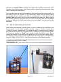
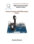
Figure 1 below depicts the Rotary inverted pendulum module coupled to the SRV02 plant
in the correct configuration. The Module is attached to the SRV02 load gear by two
thumbscrews. The Pendulum Arm is attached to the module body by a set screw. The
Inverted Pendulum experiment is a classical example of how the use of control may be
employed to stabilize an inherently unstable system. The Inverted pendulum is also an
accurate model in the pitch and yaw of a rocket in flight and can be used as a benchmark
for many control methodologies.
Figure 1 - SRV02 w/ ROTPEN Module
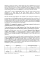
The following table is a list of the nomenclature used is the following illustrations and
derivations.
Symbol Description
Symbol Description
L
Length to Pendulum's Center of h
mass
Distance of Pendulum Center
of mass from ground
m
Mass of Pendulum Arm
Jcm
Pendulum Inertia about its
center of mass
r
Rotating Arm Length
Vx
Velocity of Pendulum Center
of mass in the x-direction
θ
Servo load gear angle (radians)
Vy
α
Pendulum Arm Deflection (radians)
Velocity of Pendulum Center
of mass in the y-direction
Page # 3
Revision: 01