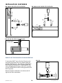
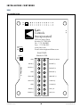
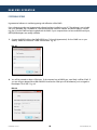
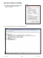
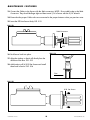
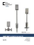
1
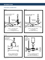
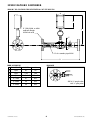
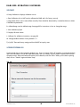
PTB 08 ATEX 1026
API COMPLIANT
An ISO 9001 certified company
KAM® OWD® OIL WATER DETECTOR
User Manual
OWDMANUAL-0213
TEL +1 713 784 0000
FAX +1 713 784 0001
Email [email protected]
KAM CONTROLS, INC.
3939 Ann Arbor Drive
Houston, Texas 77063 USA
www.KAM.com
TABLE OF CONTENTS
SECTIONTITLEPAGE
1 Introduction •Available Models and Mounting Options
•Theory of Operation
•Features
•Applications
2
2
3
3
3
2 Specifications
•Specifications
•Dimensional Drawings
4
4
5
3 Installation
9
•Installation Flow Requirements
9
•Locations/Applications
10
•General Do's and Don't's
13
•Main Line
14
•Fast Loop
17
•Wiring
20
4 OWD Operation
•Hyperterminal Software
•Calibration
•Changing the Range
•Modbus Interface
22
22
26
27
27
5Maintenance
28
•Cleaning/Inspection
28
•Troubleshooting
28
•Antenna Replacement
29
APPENDIX A: Modbus Registers
35
CAUTION:
When installing the OWD® sensor in a pipeline containing petroleum products,
petrochemicals, waste waters with the presence of pressure & temperature, and high-pressure
steam refer to the Pipeline Operators’ "Health, Safety and Environmental Policy Procedures" to
ensure safe installation.
KAM CONTROLS, INC. reserves the right to make changes to this document without notice.
OWDMANUAL 0213
1
KAM CONTROLS, INC.
INTRODUCTION
AVAILABLE MODELS and MOUNTING OPTIONS
FIG. 1-1
FIG. 1-2
Recommended KAM® SMS™
Static Mixing Spool
Recommended KAM® SMS™
Static Mixing Spool
Full-opening
Ball Valve
Full-opening
Ball Valve
Q
Q
Option 1: Retractable OWD®
on a main pipe with
2", 3", or 4" flanged seal housing
Option 2: Retractable OWD®
on a main pipe
with 2" MNPT seal housing
FIG. 1-3
FIG. 1-4
Recommended
KAM® SMS™
Static Mixing Spool
Included
KAM® SMS™
Static Mixing
Spool
P
Q
Q
Q
Option 4: 2" OWD® flow through
sensor with integrated
KAM® SMS™ Static Mixing Spool
Option 3: Fixed-mount OWD®
on a densitometer loop, with
1/2", 3/4", 1", or 2" FNPT
OWDMANUAL 0213
2
KAM CONTROLS, INC.
INTRODUCTION CONTINUED
THEORY OF OPERATION
Rugged, easy to use and extremely accurate, the KAM® OWD® Oil Water Detector is the ideal instrument for
continuously monitoring water concentration in your pipeline. It is designed in accordance with API, ASTM, ISO,
EI, UL, and DIN standards amongst others. Especially vital in production management, the OWD® sensor lets you
maximize oil production versus produced water. The simplicity of design and quality of engineering employed in
the OWD® sensor mean there are no moving parts. Patented microwave sensors measure the conductivity,
dielectric, and both the real and imaginary part of permittivity of the fluid with an extremely high degree of
accuracy, and measurement is fully automatic without the need for operator intervention or supervision. The output
signal can be sent to Flow Computers, SCADA, PLC’s or to a Central Control Room for logging or display on chart
recorders or monitors.
The KAM® OWD® sensor also uses internal references to auto calibrate for drift caused by temperature changes of
the electronics, the aging of the electronics components, fluid pressure, and fluid temperature.
The KAM® OWD® flow through model can be used in an analyzer/densitometer loop, for process optimization
where an accurate determination of water concentration is important, and it is vital to optimizing the
desalinization process. Placed on the desalter sample line, or on each sample line, the KAM® OWD® flow through
model provides real-time information about your desalter performance.
To ensure the highest degree of accuracy, the flow must be homogenous. Installed upstream of your OWD®
sensor, the patented KAM® SMP™ Static Mixing Plate or KAM® SMS™ Static Mixing Spool create a fully
homogenous mixture in your pipeline. In low velocity situations, the use of a KAM ML Measurement Loop may
be required in order to create a homogenous flow for measurement. Proper calibration, also key to complete
accuracy, can be achieved in the field with the KAM® PKF Portable Karl Fischer Moisture Analyzer. Data from the
PKF analyzer can then be entered into the OWD® sensor via IR port or corrected via RS232 at the flow computer.
Because it can be inserted into your pipe or tank through a 2", 3", or 4" hot tap, the OWD® sensor helps you
avoid costly drainage, the need for a bypass loop, or having to cut a section in the pipe. All wetted parts are machined from 316 stainless steel. Shaft lengths from 1 to 3 feet are available with off-the-shelf lengths coming in 12",
24", and 36". Metric and custom lengths are available.
TABLE 1-5 MEASUREMENT CAPABILITIES: CALIBRATED RANGE AND ACCURACIES
Range (water in oil)
Accuracy (at listed range)
OWDMANUAL 0213
0–5%
0.05%
0–10%
0.10% 0–30%
0.30%
3
0–40%
0.40%
0–100%
1.00%
KAM CONTROLS, INC.
SPECIFICATIONS
Media:
Crude oil, refined products and chemicals
Material:
Wetted parts - 316 stainless steel
Fluid temperature: To 300ºF(149ºC/High temp model available to 600ºF(315ºC)
Power requirements:
24 VDC/1 amp at 24 watts
Accuracy:
1% of full range**
Repeatability:
+/- 0.01%
Resolution: +/- 0.01%
Minimum water detection:
100 PPM
Outputs:
Selectable 4–20 mA with adjustable range
or 0–5 VDC
Alarm relay
RS232/RS485
Mounting:
½", ¾", 1" or 2" FNPT flow through
(Other sizes, including metric, are available)
2" MNPT seal housing
2", 3", or 4" flanged seal housing
Pressure ratings:
ANSI 150, 300, 600, 900, 1500, 2500
Flow conditions: Well mixed in accordance with API MPMS Chapter 8, Section 2, Table 1
Sensor dimensions:
Ø1.5" x 7" (38mmh x 178mm)
EX enclosures:
Sensor electronics - 3" x 6" x 3"
(76mm x 152mm x 76mm)
Shaft length:
12" to 36"
(305mm to 914.4mm)
Off-the-shelf lengths are 12", 24", and 36"
(609.6mm, 762mm, 914.4mm,)
Pipe Size:
½" to 48" (15mm to 1200mm)
Weight: from 20 lbs. (9kg)
* The KAM® OWD® must be installed in accordance with API MPMS Chapter 8, Section 2, Table 1.
**If entrained gas is constant, its effect is factored out. If entrained gas is introduced or removed after OWD®
calibration it will shift water cut measurement by approximately 1-2% for every 1% change in gas levels.
OWDMANUAL 0213
4
KAM CONTROLS, INC.
SPECIFICATIONS CONTINUED
DIMENSIONAL DRAWINGS
FIG. 2-1 OWD® SENSOR FOR 0–100% WATER
SL
Seal Housing
C
B
A
D
E
Electronics
Enclosure
Shaft Length ± .5"
TABLE 2-2 FLANGE SIZE AND CLASS (SL)
150
300
600
1500
900
"
INCHES
MM
INCHES
MM
INCHES
MM
INCHES
MM
INCHES
MM
2
10.25
260
10.50
267
10.50
267
11.00
279
11.25
286
3
10.75
273
10.75
273
10.75
273
11.00
279
11.40
290
4
10.75
273
10.75
273
11.00
279
11.25
286
11.65
296
TABLE 2-3 DIMENSIONS
INCHES
MM
A
1.48
38
B
4.5
114
C
7.25
184
D
4.7
119
E
5.5
140
OWDMANUAL 0213
Shaft Lengths are available in .5"
(12.7mm) increments.
Standard sizes are 24", 30", 36",
48", and 60" (609.6mm, 762mm,
914.4mm, 1219mm, 1524mm).
5
KAM CONTROLS, INC.
SPECIFICATIONS CONTINUED
FIG. 2-4 FLOW THROUGH OWD® SENSOR FOR 0–10% WATER
FT
F
A
B
TABLE 2-5 DIMENSIONS
INCHES
C
MM
E
D
INCHES
MM
TABLE 2-6 FT (FLOW THROUGH) DIMENSIONS
MM
INCHES
FNPT
A
2.75
70
D
5.75
146
½"
3.55
90.2
B
6
152
E
7.25
184
¾"
3.35
85.1
C
3.5
89
F
4.7
119
1"
3.1
78.7
FIG. 2-7 FLOW THROUGH OWD® SENSOR FOR 0–100% WATER
FT
F
A
C
B
TABLE 2-8 DIMENSIONS
INCHES
MM
D
INCHES
MM
E
TABLE 2-9 FT (FLOW THROUGH) DIMENSIONS
MM
INCHES
FNPT
A
2.75
70
D
5.75
146
½"
1.55
39.4
B
4
152
E
7.25
184
¾"
1.35
34.3
C
3.5
89
F
4.7
119
1"
1.1
27.9
OWDMANUAL 0213
6
KAM CONTROLS, INC.
SPECIFICATIONS CONTINUED
FIG. 2-10 2" OWD® FLOW THROUGH SENSOR FOR 0-100% WATER
E
B
F
A
C
TABLE 2-11 DIMENSIONS
INCHES
D
MM
INCHES
MM
A
4.25
108
D
14.5 ± .5
368 ± 13
B
3.75
95
E
7.25
184
C
2.05
52
F
4.7
119
FIG 2-12 2" WELD NECK OWD® SENSOR FOR 0-100% WATER
E
A
F
C
B
TABLE 2-13 DIMENSIONS
INCHES
D
MM
INCHES
MM
A
5.85
149
D
14.5 ± .5
368 ± 13
B
2
51
E
7.25
184
C
2
51
F
4.7
119
OWDMANUAL 0213
7
KAM CONTROLS, INC.
SPECIFICATIONS CONTINUED
FIG 2-14 2" OWD® FLOW THROUGH SENSOR WITH INTEGRATED KAM® SMS™ STATIC MIXING SPOOL
A
B
2" 150#, 300#, or 600#
weld-neck flanges
SS316 both ends
C
E
E
2" sch. seamless pipe SS316
D
TABLE 2-15 DIMENSIONS
FLANGE SIZE
INCHES
MM
A
N/A
4.7
119
B
N/A
7.25
184
C
N/A
16.5 ± 0.5
419 ± 13
D
2" 150#
21
533
2" 300#
22
559
2" 600#
22
559
OWDMANUAL 0213
FIG 2-16 EE
SS316 ½" sample valve
with ½" pitot probe
8
KAM CONTROLS, INC.
INSTALLATION
INSTALLATION FLOW REQUIREMENTS
PLEASE NOTE: In all KAM OWD Installations, the user should insure that the KAM OWD is installed in a turbulent
flow with the Reynolds Number above 2000. Additionally, all KAM OWD's should be installed in accordance with
API MPMS Chapter 8, Section 2, Table 1.
For Low Range (0 – 5% Water in Oil) KAM OWD's, the sensor must be installed in the vertical down flow with
a minimum flow velocity of 4 feet per second. A KAM SMS Static Mixing Spool is required if the flow velocity is
between 4 and 7 feet per second. FIG. 3-1.
For KAM OWD's operating in the Oil Continuous Phase, the sensor must be installed in the vertical down flow. A
KAM SMS Static Mixing Spool is required if the flow velocity is between 4 and 7 feet per second. FIG. 3-1.
For KAM OWD's operating in the Water Continuous Phase, the sensor must be installed in the vertical up flow. A
KAM SMS Static Mixing Spool is required if the flow velocity is between 4 and 7 feet per second. FIG. 3-2.
In situations where the flow velocity is less that 4 feet per second, KAM CONTROLS recommends the installation of
a KAM ML Measurement Loop, incorporating suction and injection nozzles, a pump, and the OWD on a separate
loop, ensuring a homogenous, high-velocity flow across the measurement sensor. FIG. 3-3.
The KAM OWD may be installed horizontally when the minimum flow velocity is above 10 feet per second.
FIG. 3-1 KAM® OWD® INSTALLATION VERTICAL FLOW DOWN
FIG. 3-3 KAM® OWD® INSTALLED ON A KAM ML MEASUREMENT LOOP
Q
Q
SUCTION
KAM SMS
STATIC MIXING
SPOOL
INJECTION
LOW RANGE AND
OIL CONTINUOUS
PHASE OPERATION
OWD
FIG. 3-2 KAM® OWD® INSTALLATION VERTICAL FLOW UP
WATER CONTINUOUS
PHASE OPERATION
The KAM ML Measurement Loop utilizes a
pump to draw a representative flow from the
main line into a circulation loop, incorporating a
KAM OWD. The loop flow is injected back into
the main pipeline upstream of the suction site,
creating mixing and homogeneity prior to
suction. A homogenous flow of 10-13 fps is
maintained at the sensor head for the most
accurate measurement at all times.
KAM SMS
STATIC MIXING
SPOOL
Q
OWDMANUAL 0213
9
KAM CONTROLS, INC.
INSTALLATION CONTINUED
EFFECTS OF ENTRAINED GAS
If entrained gas is constant, its affect is factored out. If entrained gas is introduced or removed after OWD®
calibration it will shift water cut measurement by approximately 1-2% for every 1% change in gas levels.
RECOMMENDED LOCATION BY APPLICATION
In separator applications, KAM CONTROLS
recommends that the OWD® sensor should
be installed immediately downstream of the
Separator Dump Valve in a vertical section of
the pipe with the flow travelling downward.
If possible, it should also be downstream of a
KAM® SMS™ Static Mixing Spool or a KAM®
SMP™ Static Mixing Plate. FIG. 3-4.
FIG. 3-4 KAM® OWD® SEPARATOR INSTALLATION
SEPARATOR
Q
KAM SMS
STATIC MIXING
SPOOL
A second installation option for this application is in a horizontal pipe immediately downstream of the Separator
Dump Valve in an OWD® spool integrated with a KAM® static mixer. FIG. 3-5.
FIG. 3-5 KAM® OWD® ALTERNATE SEPARATOR INSTALLATION
Q
SEPARATOR
KAM SMS
STATIC MIXING
SPOOL
OWDMANUAL 0213
10
KAM CONTROLS, INC.
INSTALLATION CONTINUED
In a refinery/feedstock application, KAM CONTROLS recommends that the OWD® sensor be installed far enough
in advance of the “Refinery Unit” to give time to take corrective action in instances where the OWD® senses
unacceptable high water levels. FIG. 3-6.
FIG. 3-6 KAM® OWD® REFINERY INSTALLATION
KAM® SMS™
STATIC MIXING SPOOL
CAT CRACKER/
BOILER
Q
For ideal performance in desalter applications, the desalter tank should incorporate a progressive series of 8
sample lines, each with its own draw-off valve and flow-through OWD® sensor, plus an additional OWD® sensor
located on the outgoing oil line. FIG. 3-7.
FIG. 3-7 KAM® OWD® IDEAL DESALTER INSTALLATION
Q
Q
Q
Q
Q
OWDMANUAL 0213
11
KAM CONTROLS, INC.
INSTALLATION CONTINUED
For optimal batch detection, Kam Controls recommends that you install the in-station OWD® sensor at the first
accessible pipeline location inside the terminal fence-line — upstream of the interface cut valve(s).
This allows the operator ample time to open/close the cut valves prior to the arrival of the product interface.
KAM Controls also strongly recommends that you utilize a preview (or out-station) OWD® sensor. This lets the
operator decide how to
optimize
each batch cut prior to actually making the batch cut at the in-station and gives
TERMINAL
FENCE
the operator more confidence in their decisions as well as the time to identify and resolve any issues that may arise
during a critical interface. FIG. 3-8.
FIG. 3-8 OPTIMAL BATCH DETECTION OWD® INSTALLATION
O
W
D
O
W
D
Terminal fence line
O
W
D
Typically
1-2 Miles
Out-station/Preview
OWD®
OWDMANUAL 0213
In-station
OWD®
12
KAM CONTROLS, INC.
INSTALLATION CONTINUED
GENERAL INSTALLATION DO'S AND DON'TS
Always install OWD®
sensors with the
electronics enclosure
shaded from direct
sunlight.
DO NOT use Teflon
tape on threads connecting to the OWD®
flow through sensor.
DO use liquid thread
sealant.
OWDMANUAL 0213
13
KAM CONTROLS, INC.
INSTALLATION CONTINUED
PRIOR TO INSTALLATION
Remove all the protective packaging materials, and ensure that the OWD® sensor was not damaged
during transit.
REMINDER: Please refer to the Installation Flow Requirements on P. 9 of this manual to ensure proper sensor
placement where at all possible. Flow conditions must satisfy API MPMS Chapter 8.2 requirements in order to
achieve accurate OWD performance.
In cold weather, if OWD is exposed to an open environment, KAM CONTROLS recommends operators insulate the OWD, and if the pipeline is heated that the heating trace be extended to include the OWD.
If the pipeline is not going to flow for extended amount of time and the pipe is not heated then OWD should
be taken out to avoid damage to the sensor probe by freezing water.
INITIAL CALIBRATION
Though the OWD has been calibrated in the factory, operators should conduct an initial calibration in process
conditions. This can be done in two ways:
Off-line: Prior to installation, operators can go through the procedures for off-line calibration outlined on page 26
of this manual. This method requires samples of 100% produced water and dry oil or oil with a known percentage
of water.
On-line: After installation, operators can follow calibration procedures for in-line calibration outlined on page 26 of
this manual. This method requires accurate sampling and sample processing.
MAIN LINE INSTALLATION
The KAM® OWD® sensor should be installed
according to FIG. 3-13. A full-opening ball valve is
used to isolate the OWD® sensor from the pipeline
during installation or removal. The seal housing of
the OWD® sensor allows the probe to be inserted
and removed from the pipe under pressure and
flow conditions. It is the user’s responsibility to
ensure that the OWD® sensor be placed at the most
representative point within the flow
profile (see location recommendations above).
The OWD® sensor should be inserted so that the
window of the probe is located in the center of the
diameter of the pipeline.
FIG. 3-13 KAM® OWD® INSTALLED ON A MAIN PIPE
Locking Collar
Seal Housing
Full-opening
Ball Valve
Note: If line pressure exceeds 100 psi, use a KAM®
IT Insertion Tool when installing/removing
the KAM® OWD® sensor.
OWDMANUAL 0213
Socket Cap Screw
14
KAM CONTROLS, INC.
INSTALLATION CONTINUED
1. Prior to mounting verify that the tip of the sensor
is all the way inside the seal housing.
FIGS. 3-14, 3-15.
2. If sensor is not fully enclosed inside the seal
housing, pull the shaft back until the probe is
all the way in the seal housing and tighten
the Socket Cap Screws on the locking collar.
This will prevent the OWD® shaft from sliding
and the probe from getting damaged during
mounting.
FIG. 3-14
FIG. 3-15
3. Measure the distance (D1) from the outside diameter of main pipe to the end of the
connection where the OWD® sensor is going to be installed. FIG. 3-16.
FIG. 3-16
D1
D1
4. Calculate the minimum insertion distance for the OWD®.
Minimum insertion distance (MID) = D1 + Pipe Wall Thickness (WT) + Gasket Thickness + A (See TABLE 3-16)
Example for D1=16", WT =1/4", Gasket Thickness=1/8" and a 0-100% OWD® sensor:
MID = 16 + 1/4 + 1/8 + 3
MID = 19 3/8" or 19.375"
TABLE 3-17
OWD® WATER RANGE
A/INCHES
0-10% SENSOR
5"
0-100% SENSOR
3"
OWDMANUAL 0213
15
KAM CONTROLS, INC.
INSTALLATION CONTINUED
FIG. 3-18
5. Measure the calculated MID from the top of the
Locking Collar and place a mark with a permanent
marker or tape on the Shaft. FIG. 3-18.
MID
6. Bolt or screw the OWD® sensor to the valve or designated installation location.
(KAM CONTROLS recommends using thread sealant and not Teflon tape for the threaded OWD®).
7.
Open full opening valve.
8. Loosen Socket Cap Screws on the locking collar.
9. Push OWD® sensor in until the mark is at the top edge of the locking collar. Ensure that OWD® flow indicator is
aligned with pipeline flow direction. FIG. 3-19.
FIG. 3-19
Mark
Hex Nuts
10. Re-tighten the Socket Cap Screws.
11. Tighten the hex nuts holding down the Locking Collar one half turn. (Fig. 3-19) These should never be overtightened. Their major function is to apply light pressure on the chevron packing to ensure a seal between the
seal housing body and the insertion shaft.
REMOVING THE OWD® SENSOR
To remove the OWD® sensor, first shut off power to the instrument. Loosen the Socket Cap Screw on the Lock Down
Collar. Slide the OWD® sensor upward until the probe rests inside the seal housing. Next, close the Full-opening
Ball Valve tightly. Drain oil from valve if possible. The OWD® sensor may now be unbolted from the system.
Note: If line pressure exceeds 100 psi, use a KAM® IT Insertion Tool when installing/removing
the KAM® OWD® sensor.
Removal should be conducted in accordance with all regional and Class requirements.
OWDMANUAL 0213
16
KAM CONTROLS, INC.
INSTALLATION CONTINUED
FAST LOOP INSTALLATION
PRIOR TO INSTALLATION
Remove all the protective packaging materials, and ensure that the OWD® sensor was not damaged
during transit.
In cold weather, if OWD is exposed to an open environment, KAM CONTROLS recommends operators
insulate the OWD, and if the pipeline is heated that the heating trace be extended to include the OWD.
If the pipeline is not going to flow for extended amount of time and the pipe is not heated then OWD should
be taken out to avoid damage to the sensor probe by freezing water.
The KAM OWD must be installed in accordance with API MPMS Chapter 8.2, Table 1.
Please ensure that the flow in the analyzer loop represents the main pipe flow. The analyzer loop flow velocity must
be equal to or greater than the maximum main line flow velocity.
If your installation utilizes a pump to pump the fluid through the OWD® cell, KAM CONTROLS recommends that the
pump be installed upstream of the OWD® sensor to create mixing. KAM CONTROLS also recommends installing a
small KAM® SMS™ Static Mixing Spool at the OWD® cell inlet. FIG. 3-21.
The Inlet and outlet of the OWD® Cell are ½", ¾", 1" or 2" FNPT. (Additional sizes, including metric, are
available.) KAM CONTROLS recommends using liquid thread sealant and not Teflon tape for the threads to reduce
the chances of the threads galling.
Refer to FIGURE 3-20 for vertical installation and FIGURE 3-22 for horizontal installation.
INITIAL CALIBRATION
Though the OWD has been calibrated in the factory, operators should conduct an initial calibration in process
conditions. This can be done in two ways:
Off-line: Prior to installation, operators can go through the procedures for off-line calibration outlined on page 26
of this manual. This method requires samples of 100% produced water and dry oil or oil with a known percentage
of water.
On-line: After installation, operators can follow calibration procedures for in-line calibration outlined on page 26 of
this manual. This method requires accurate sampling and sample processing.
OWDMANUAL 0213
17
KAM CONTROLS, INC.
INSTALLATION CONTINUED
FIG. 3-22 KAM® OWD® HORIZONTAL FAST LOOP INSTALLATION
FIG. 3-20 KAM® OWD® VERTICAL FAST LOOP INSTALLATION
Q
Q
Q
P
Q
Q
P
Q
Q
Q
FIG. 3-21 KAM® OWD® VERTICAL FAST LOOP INSTALLATION
Q
KAM SMS™
®
REMOVING THE OWD® SENSOR FROM ANALYZER LOOPS AND ML MEASUREMENT LOOPS
To remove the OWD® sensor, first shut off power to the
instrument. Discontinue flow in loop fram the main line
and drain fluid from loop. The probe can removed from
the housing by removing screws connecting probe and
shaft to flanged probe housing or OWD cell. The probe
can then be lifted from the cell for testing/inspection/calibration purposes.
FIG. 3-23
Removal should be conducted in accordance with all
regional and Class requirements.
OWDMANUAL 0213
18
KAM CONTROLS, INC.
INSTALLATION CONTINUED
FAST LOOP INSTALLATION DO'S AND DON'TS
Always install OWD®
flow through sensors
with the flow of the
fast loop moving from
top to bottom through
the OWD® cell.
Q
Q
Q
Q
Q
Q
Q
Q
Q
Q
Q
Q
OWDMANUAL 0213
19
KAM CONTROLS, INC.
INSTALLATION CONTINUED
WIRING
FIG. 3-23 WIRING DIAGRAM
R1
D1
+
Kam
Controls
Incorporated
3939 Ann Arbor Drive
Houston, TX 77063 USA
Tel + 1 713 784 0000
Fax + 1 713 784 0001
www.Kam.com
E-mail [email protected]
Bluetooth
+
D3
R5
ZigBee
+
D2
R4
KAM OWD
Made in USA
GND
DENSITY IN (AIN2)
OWD Rev. 2
DIG IN (-)
DIG OUT (-)
DIG IN (+)
DIG OUT (+)
GND
ANA OUT (-)
RS232 RX
ANA OUT (+)
RS232 TX
4-20mA (-)
GND
OWDMANUAL 0213
4-20mA (+)
RS485 (-)
24V (-) in
RS485 (+)
24V (+) in
20
KAM CONTROLS, INC.
INSTALLATION CONTINUED
All wiring and maintenance on the KAM OWD must be done in accordance with regional and classification
requirements. It is the user's responsibility to understand these requirements.
It is also recommended that the OWD be wired with flexible wiring/conduit with additional slack/length in the
wire to accommodate insertion, removal, and testing.
Operator's should take all possible precautions to avoid any moisture from entering the electronics enclosure.
The enclosure should not be left open in inclement weather or for long periods of time, especially during
operation as condensation will accumulate. It should be tightly screwed shut and all conduits should be sealed
and secured in accordance with regional and classification requirements. Do not power wash the unit.
INPUTS
24V (–) IN
24V (+) IN
GND
Power
DIG IN (–)
DIG IN (+)
Pulse input, discrete input for different modes of operation (0 or 5 volt)
DENSITY IN
OUTPUTS
4-20 mA (–) Current output, source powered
4-20 mA (+)
AN OUT (–)
AN OUT (+)
Can be 4-20 mA or analog voltage
DIG OUT (–) Alarm or relay (digital contact closure)
DIG OUT (+)
INPUT/OUTPUT
RS232
RS485
Consol port – communication interface for calibration, connection to PLC
Modbus interface
LED INDICATORS
D1
D2
D3
Power
ZigBee wireless for communication interface
Bluetooth wireless for communication interface
SERIAL PORT CONNECTIONS
DB9 (female)
5
GND
3 RS232RX
2 RS232TX
OWDMANUAL 0213
21
KAM CONTROLS, INC.
KAM OWD OPERATION
HYPERTERMINAL SOFTWARE
Hyperterminal software is used during testing and calibration of the OWD.
Prior to beginning make sure Hyperterminal software has been installed on your PC. The software is not included
with your instrument, but is available as a free download from numerous websites. An RS232 cable for connecting your PC to the OWD has been supplied with the OWD. If your computer does not have an RS232 serial port,
RS232/USB adapters are readily available.
1.
Connect the RS232 cable to the OWD RS232 port. To launch Hyperterminal, click on OWD icon on your
desktop. Name the connection "OWD" and hit return. Fig. 4-1.
FIG. 4-1
2.
You will be promted to select a COM port. If the computer has an RS232 port, most likely it will be COM1. If
you are using an adapter like a USB to RS232 Converter the COM port will be whatever port is assigned to
the adapter. Click "OK." Fig. 4-2.
FIG. 4-2
OWDMANUAL 0213
22
KAM CONTROLS, INC.
KAM OWD OPERATION CONTINUED
3. Use the settings shown in Fig. 4-3 and click OK.
4. Click on the properties icon. FIG. 4-4
5. Click on the settings tab. FIG. 4-5
FIG. 4-3
FIG. 4-4
FIG. 4-5
6. Click on the ASCII setup button.
OWDMANUAL 0213
23
KAM CONTROLS, INC.
KAM OWD OPERATION CONTINUED
7.
Check the window for Echo Typed Characters Locally
and click OK. Hyperterminal is now setup for
operation with the OWD.
FIG. 4-6
8. You will see a blank screen. Hit enter to see OWD prompts. FIG. 4-7.
FIG. 4-7
OWDMANUAL 0213
24
KAM CONTROLS, INC.
KAM OWD OPERATION CONTINUED
OWD PROMPTS
d: Dump Calibrations–displays calibration curves
c: Enter Calibration–this is NOT used to calibrate the OWD and is for factory use only
o: Enter offset–allows users to enter offsets manually. These should be determined by a trained technician or KAM
CONTROLS representative.
R: 4-20mA Range–sets the 4-20mA range. See page 29 for instructions on how to change the range.
s: Save calibrations/inputs
Z: Displays all sensor values
L: Calibrate–for calibration instructions, see page 28
M: Change Modbus Address: Factory default is "1"
T/u/v/W/i: These are factory settings and should NOT be input by users
CAPTURING HYPERTERMINAL DATA
Hyperterminal data can be captured in multiple ways. Users can simply "select all" and then cut and paste the data
into a word document. Or from the OWD data screen, click on "Transfer." Fig. 4-8. Select "Capture Text" from the
drop-down menu. Select and name and location for the data file, and click "Start." When you are done capturing
data, click on "Transfer" again and select "Stop."
FIG. 4-8
OWDMANUAL 0213
25
KAM CONTROLS, INC.
KAM OWD OPERATION CONTINUED
HOW TO CALIBRATE THE KAM® OWD® USING BRINE AND DRY OIL
Though the OWD has been calibrated in the factory, it should be calibrated in process conditions prior to use.
This can be done using 100% brine (produced water) and 100% dry oil in buckets as outlined below, or it can be
done with online sampling. For the brine/dry oil method, in addition to fluid samples, operators will need
appropriate tools for the extraction of the OWD, an RS232 cable (supplied) or an RS232/USB adapter, and a PC
equipped with Hyperterminal software.
1.
If the OWD has been installed, remove from the line according to the instructions on page 16 for insertable
models and page 18 for models installed on fast loops and ML Measurement Loops. Clean the OWD sensor
according the guidelines on page 28 of this manual.
2.
Restore power to the OWD and connect to a PC via RS232 or RS232/USB adapter. Initiate Hyperterminal
setup. For information on setting up Hyperterminal software, see page 22.
3.
Let the OWD sensor warm up for 20 minutes.
4.
Insert the sensor in a bucket with brine (produced water). Probe should remain in brine until a stabilized temperature is observed. Readings should show 100% water in the Hyperterminal. As all water in crude oil has
salt, the OWD sensor has already been calibrated for salt water. You will not get an accurate reading if you
use fresh water for testing. It should also show 20mA if the mA range is calibrated for 0-100% which you can
measure at the output terminal. Regardless of readings, the sensor should be recalibrated.
5.
Enter "L" on the Hyperterminal interface and hit ENTER. A "Water %" prompt will appear. Enter "100." Hit
ENTER. Type "s," then ENTER to save.
6.
Remove probe from brine, and thoroughly clean and dry the probe.
7.
Insert the OWD sensor into a bucket or a jar filled with a sample of dry oil. In order to accurately test the
OWD sensor, you must use oil that does not have any water in it or which has a known, low percentage
of water. The water percentage reading in the Hyperterminal should show 0% or reflect the known water
percentage.
8.
Enter "L" on the Hyperterminal interface. A "Water %" prompt will appear. Enter "0" or the known percentage
of water. Hit ENTER. Type "s," then ENTER to save.
9.
The OWD has now been calibrated to process conditions and can be installed.
0N-LINE CALIBRATION OF THE KAM® OWD®
PLEASE NOTE: The following calibration steps should only be conducted during initial installation with process
conditions, when process conditions have changed, or when OWD readings indicate a slight drift off acceptable
accuracies. You will need an RS232 cable (supplied) or an RS232/USB adapter, a PC equipped with
Hyperterminal software, and a means for collected and measuring samples.
1. Connect PC to the OWD sensor via supplied RS232 serial port or RS232/USB adapter. Launch
Hyperterminal and hit ENTER. For Hyperterminal setup, see page 22.
2. Take an accurate (fully homogenous) sample from the pipeline close to the sensor location on the pipeline,
and at the same time type "L" for calibration in the Hyperterminal and hit ENTER. A "Water %" prompt will
appear.
OWDMANUAL 0213
26
KAM CONTROLS, INC.
KAM OWD OPERATION CONTINUED
3. Determine water percentage in sample using a KAM Karl Fischer Moisture Analyzer (recommended), or appropriate method. Enter the determined sample water percentage into Hyperterminal prompt and hit ENTER.
4. Type "S", then hit ENTER to save.
5. The KAM® OWD® is now calibrated.
This process can be repeated if the sample taken was a bad sample or the percent of water obtained from the
sample taken was not accurate.
HOW TO CHANGE THE HIGH/LOW (4-20 mA) RANGE
1.
To enter or change the desired range for the OWD sensor, type “R” and hit ENTER. Prompts will
appear for the low and then the high ends of the range.
2.
After entering both, type “S” to save. The range has been set and the Hyperterminal will return to the OWD
Optimizer prompt menu.
SETTING UP A MODBUS INTERFACE
1.
To set Modbus variables, type "M" and hit ENTER.
2.
The prompt is for an ID for the slave device. This ID MUST BE UNIQUE from any other Modbus device
connected and a value between 1-255.
SYSTEM SETTINGS:
Modbus Baudrate: 9600.
Protocol is RTU Modbus.
See APPENDIX A for designated MODBUS Registers.
OWDMANUAL 0213
27
KAM CONTROLS, INC.
MAINTENANCE
CLEANING AND INSPECTION
If probe is removed from the line for inspection NEVER use sharp or metallic objects such as a knife or screw driver
to clean the antenna, especially the Teflon coated antenna. Do NOT power wash the unit.
Instead, to remove any oil residues for visual inspection use a clean cloth with oil solvent or part washer.
Preferred solvents include, any petroleum solvent such as mineral spirits, xylene, toluene, gasoline, or diesel. Do
not use WD40 or other chemicals.
If you have a question regarding cleaning solvents, please contact KAM CONTROLS directly at +1 713 784-0000,
or email: [email protected]
During inspection, ensure that there are no foreign objects stuck in the probe or attached to the antennas and that
the Teflon coating is completely intact without any chips or scratches.
TROUBLESHOOTING
If OWD data begins to differ slightly or gradually from sampling data and falls outside of acceptable accuracies,
this is most likely caused by drift. The OWD should be recalibrated using the on-line recalibration procedure outlined on page 26.
If OWD data suddenly veers from historical norms or sampling data, it needs to be removed from the line and
inspected using the steps outlined below.
1. Remove the OWD from the line according to the instructions on page 16 for insertable models and page 18
for models installed on fast loops and ML Measurement Loops. Clean the OWD sensor according the guidelines above, and check for any debris in the probe or on the antennas that could affect measurement. Check
the condition of both antennas.
2. If there is debris clogging the sensor or coating the antennas in any way, this is most likely the cause of any
measurement anomalies. Once the OWD has been cleaned, it can be reinstalled. It does not need
recalibration.
3. If there is no evidence of debris, the OWD must be tested in order to determine the cause of the measurement
error. This requires samples of 100% brine (produced water) and dry oil or oil with a known, low percentage of water, an RS232 cable (supplied) or an RS232/USB adapter, and a PC equipped with Hyperterminal
software.
4. Connect the OWD to a PC via RS232 or RS232/USB adapter, and turn the power on. Initiate Hyperterminal
setup. For information on setting up Hyperterminal software, see page 22.
5. Let the OWD sensor warm up for 20 minutes.
6. Insert the sensor in a bucket with brine (produced water). Probe should remain in brine until a stabilized temperature is observed. As all water in crude oil has salt, the OWD sensor has already been calibrated for salt
water. You will not get an accurate reading if you use fresh water for testing.
OWDMANUAL 0213
28
KAM CONTROLS, INC.
MAINTENANCE CONTINUED
7.
Capture and save screen data according to instructions outlined on page 25.
8. Thoroughly clean and dry the probe.
9. Insert the OWD sensor into a bucket or a jar filled with a sample of dry oil. In order to accurately test the
OWD sensor, you must use oil that does not have any water in it or which has a known, low percentage
of water.
10. Capture and save screen data according to instructions outlined on page 25.
11. Captured data should be sent to the KAM CONTROLS factory for analysis or analyzed by a KAM
CONTROLS trained technician. The technician will then advise the operator on the next steps.
OWDMANUAL 0213
29
KAM CONTROLS, INC.
MAINTENANCE CONTINUED
ANTENNA REPLACEMENT
TOOLS REQUIRED
1. Phillips Screwdriver Size 0
2. 1/16" Allen Wrench
3. 5/64" Allen Wrench
4. 5/16" Allen Wrench
MATERIALS REQUIRED
1. Uncoated Antenna
2. Coated Antenna
3. (2) 2-004 O-rings
4. (2) 2-009 O-rings
5. Medium Strength Loctite
Contact KAM CONTROLS
at +1 713 784 0000,
Fax to +1 713 784 0001,
or email [email protected].
Ask for Part Number: OWD ANT
DISASSEMBLY
1.
Remove all (6) 8-32 Set Screws using the 5/64" Allen Wrench. Make sure that the wrench in fully inserted or
the Set Screws will strip. FIG. 5-1
FIG. 5-1
8-32 Set Screws
Junction Box Lid
2. Unscrew lid to round junction
box (FIG. 5-1) and ensure that
cables are somewhat slack. If
not, untie/loosen the cables
prior to pulling probe away
from housing.
FIG. 5-2
3. Slowly pull Probe away from
Housing to gain access to the
SMA connectors. Do not pull
too hard or too far as the wires
can be damaged. FIG. 5-2
OWDMANUAL 0213
RTD
30
SMA Connectors
KAM CONTROLS, INC.
MAINTENANCE CONTINUED
4. Make a note of which color cable goes to which antenna. For example: Red cable goes to green antenna.
5. Loosen and unscrew completely the SMA Connectors using the 5/16" Allen Wrench.
6. Pull to remove the RTD. DO NOT pull from the wires. FIG. 5-2
7.
Unscrew the (4) 4-40 Screws on the top of the sensor using
the Phillips Screwdriver Size 0. FIG. 5-3
FIG. 5-3
4-40 Screws
8. Remove the Cover from the Sensor. FIG. 5-4
FIG. 5-4
9. Remove the (4) Set Screws at the bottom of the Sensor using the 1/16" Allen Wrench. Be sure to insert wrench
fully or screws will strip. FIG. 5-5
10. Push the Bottom Cover from the inside of the Sensor until it is completely free. FIG. 5-5
FIG. 5-5
6-32 x ¼" Set Screw
OWDMANUAL 0213
31
KAM CONTROLS, INC.
MAINTENANCE CONTINUED
11. Pushing from the bottom, remove the Antennas. FIG. 5-6
FIG. 5-6
12. Remove the Antennas from the PEEK Seal Holders by turning them counterclockwise. FIG. 5-7
13. Slide the Seal Holder Covers off the Antennas. FIG. 5-7 NOTE: The Seal Holder Cover for the
Coated and Uncoated Antennas are different. The cover for the Coated Antenna has a larger hole.
14. Remove the 2-009 and 2-004 O-rings from the Seal Holder. FIG. 5-7
FIG. 5-7
Seal Holder
Seal Holder Cover
2-004 O-ring
2-009 O-ring
15. Clean Sensor Body with parts washer and let it dry.
OWDMANUAL 0213
32
KAM CONTROLS, INC.
MAINTENANCE CONTINUED
REASSEMBLY
1. Install the new 2-009 O-rings on the Seal Holder. FIG. 5-8A
2. Screw the new Antennas into the Seal Holder. The Antennas need to extend .175–.180" from the top
of the Seal Holder. FIG. 5-8A
3. Slide the new 2-004 O-rings on the Antennas. FIG. 5-8B
4. Slide Seal Holder Covers behind the 2-004 O-rings. Make sure the use the Seal Holder Cover with
the larger center hole with the Coated Antenna. FIG. 5-8B
5. Add a small amount of grease to the 2-004 O-rings.
6. Push the 2-004 O-rings inside the Seal Holder using the Seal Holder Covers. FIG. 5-8C
FIG. 5-8
.175–.180"
A.
2-009 O-ring
B.
2-004 O-ring
Seal Holder Cover
C.
7. Add a small amount of grease to the 2-009 O-rings.
8. Insert Seal Holder/Antenna assembly into the Sensor Body. FIG. 5-9
FIG. 5-9
OWDMANUAL 0213
33
KAM CONTROLS, INC.
MAINTENANCE CONTINUED
9. Place Sensor Cover onto the Sensor Body. Be careful to ensure that the holes for the RTD are in
alignment.
10. Add a small amount of Loctite to the (4) 4-40 Screws and install them into the Sensor Body, holding
the Cover in place. FIG. 5-10
FIG. 5-10
4-40 Screws
11. Push Bottom Cover back into place. Make sure holes align with the Antennas.
12. Add Loctite to all (4) 6-32 Screws and install them into the Sensor Body, securing the Bottom Cover.
FIG. 5-11
FIG. 5-11
6-32 Screw
OWDMANUAL 0213
34
KAM CONTROLS, INC.
MAINTENANCE CONTINUED
13. Connect the Cables to the Sensor with the SMA connectors. NOTE: Do not add Loctite to the SMA
Connectors. They should be finger tight and then turned 1/16 of a turn with the 5/16" Wrench.
14. Ensure that the proper Cable colors are connected to the proper Antenna colors per previous notes.
15. Insert the RTD into Sensor Body. FIG. 5-12
FIG. 5-12
SMA Connectors
RTD
FIG. 5-13
16. Push Sensor back into place.
17. Align the window so that it will directly face the
direction of the flow. FIG. 5-13
18. Add Loctite to all (6) 8-32 Set Screws and install
them back in Sensor. FIG. 5-14
Flow
FIG. 5-14
8-32 Set Screws
OWDMANUAL 0213
35
KAM CONTROLS, INC.
APPENDIX A: MODBUS INTERFACE REGISTERS
MODBUS FUNCTION
01 Discrete Coil Status
USE REGISTERS
Reads output coil status,
digital outputs
0x00001–0x00016: Digital outputs 0–15
02 Discrete Input Status
Reads state of individual
digital inputs
0x10001–0x10024: Digital inputs 0–23
03 Holding Register
Reads and writes to the
DAC channels (0-3).
Takes a converted float
value (from 2 unsigned
int values) and updates
the DAC output values
(in Volts 0-10VDC).
0x40001–0x40002: Float value for DAC 0
0x40003–0x40004: Float value for DAC 1
0x40005–0x40006: Float value for DAC 2
0x40007–0x40008: Float value for DAC 0
40100–40999: 16–bit values
41000–41999: 32–bit values
42000–44999: Float values
45000–47299: Modbus registers
40100: Alarm setpoint
40101: Alarm setpoint prior to change
40102: On or off alarm report
40103: On or off alarm report
40104: On or off alarm report
40105: True when value over alarm value for dead-band time. Reset when value below alarm value for dead-band time.
40106: Signal to reset transaction
40107: Water content integer
40108: AD0 raw value
40109: AD1 raw value
40110: Low-end output at 4ma prior to change
40111: Low-end output at 4ma
40112: High-end output at 20ma
40113: High-end output at 20ma prior to change
40114: Number of user block saves (Limit to 50,000)
41000: Sample period in seconds
41001: Sample period in seconds prior to change
41002: Alarm dead–band inter-value timer
41003: Alarm dead–band start time
41004: Alarm dead–band current time
41005: Alarm inter-value timer
41006: Alarm start time
41007: Alarm current time
41008: Array of time of alarms
41009: Array of time of alarms
41010: Array of time of alarms
41011: Value at time of alarm
41012: Value at time of alarm
41013: Value at time of alarm. Reset when value below alarm value for dead-band time.
41014: Amount of measured material
41015: Material less water
41016: Average water
41017: Transaction intervalue timer
41018: Transaction start time
41019: Sample period in second
OWDMANUAL 0213
36
KAM CONTROLS, INC.
APPENDIX A CONTINUED
MODBUS FUNCTION
USE 03 Holding Register continued
OWDMANUAL 0213
REGISTERS
41020: Sample start time
41021: Sample current time
41022: Mode: oil continuous/water continuous
41023: Modify table: 0=oil continuous
1=water continuous
41024: Set to 1 to signal table modification ready. Reset to –1 to indicate not ready.
41025: Set to 1 to signal write UB
41026: Modify sensor1 TempCorf: 1
Modify sensor2 TempCorf: 2
41027: Set to 0–19 to indicate temperature curve
modification ready. Reset to –1 to indicate not
ready.
41028: Temperature value input by user
41029
41030 – 41049: Temperature table temperatures
42000: Trend 0
42001: Trend 1
42002: Trend 2
42003: Trend 3
42004: Trend 4
42005: Trend 5
42006: Trend 6
42007: Trend 7
42008: Trend 8
42009: Trend 9
42010: Trend 10
42011: Trend 11
42012: Trend 12
42013: Trend 13
42014: Trend 14
42015: Trend 15
42016: Trend 16
42017: Trend 17
42018: Trend 18
42019: Trend 19
42020: AD0 input
42021: AD1 input
42022: AD2 oil/water continuous input
42023: DA0 output
42024: Water content oil continuous sensor 1
42025: Water content oil continuous sensor 2
42026: Water content water continuous sensor 1
42027: Water content water continuous sensor 2
42028: Water content float
42029: Sensor 1 offset input by user
42030: Sensor 1 offset input by user
42031: Sensor 2 offset input by user
42032: Sensor 2 offset input by user
42033: Storage register for Modbus table index water value
42034 Storage register for Modbus table sensor 1 value
42035 Storage register for Modbus table sensor 2 value
42036: AD3 temperature voltage input
42037: Temperature value input
37
KAM CONTROLS, INC.
APPENDIX A CONTINUED
MODBUS FUNCTION
USE 03 Holding Register continued
OWDMANUAL 0213
REGISTERS
42038: Temperature input low voltage
42039: Temperature input low value
42040: Temperature input high voltage
42041: Temperature input high value
42042: Sensor 1 temperature correction
42043: Sensor 2 temperature correction
42044: Water factor 0.00 – 9.99
42045: Sensor 1 temperature correction 0–10v
42046: Sensor 1 temperature correction 10v
42047: Sensor 1 temperature correction 0–10v
42048: Sensor 1 temperature correction 10v
42049: Sensor 1 temperature correction 0–10v
42050: Sensor 1 temperature correction 10v
42051: Sensor 1 temperature correction 0–10v
42052: Sensor 1 temperature correction 10v
42053: Sensor 1 temperature correction 0–10v
42054: Sensor 1 temperature correction 10v
42055: Sensor 1 temperature correction 0–10v
42056: Sensor 1 temperature correction 10v
42057: Sensor 1 temperature correction 0–10v
42058: Sensor 1 temperature correction 10v
42059: Sensor 1 temperature correction 0–10v
42060: Sensor 1 temperature correction 10v
42061: Sensor 1 temperature correction 0–10v
42062: Sensor 1 temperature correction 10v
42063: Sensor 1 temperature correction 0–10v
42064: Sensor 1 temperature correction 10v
42065
42066
42067
42068
42069
42070
42071
42072
42073
42074
42075: Sensor 1 temperature correction 0–10v
42076: Sensor 1 temperature correction 10v
42077: Sensor 1 temperature correction 0–10v
42078: Sensor 1 temperature correction 10v
42079: Sensor 1 temperature correction 0–10v
42080: Sensor 1 temperature correction 10v
42081: Sensor 1 temperature correction 0–10v
42082: Sensor 1 temperature correction 10v
42083: Sensor 1 temperature correction 0–10v
42084: Sensor 1 temperature correction 10v
42085: Sensor 1 temperature correction 0–10v
42086: Sensor 1 temperature correction 10v
42087: Sensor 1 temperature correction 0–10v
42088: Sensor 1 temperature correction 10v
42089: Sensor 1 temperature correction 0–10v
42090: Sensor 1 temperature correction 10v
42091: Sensor 1 temperature correction 0–10v
42092: Sensor 1 temperature correction 10v
38
KAM CONTROLS, INC.
APPENDIX A CONTINUED
MODBUS FUNCTION
USE 03 Holding Register continued
OWDMANUAL 0213
REGISTERS
42093: Sensor 1 temperature correction 0–10v
42094: Sensor 1 temperature correction 10v
40100: Alarm setpoint
40101: Alarm setpoint prior to change
40102: On or off alarm report
40103: On or off alarm report
40104: On or off alarm report
40105: True when value over alarm value for dead-band time. Reset when value below alarm value for dead-band time.
40106: Signal to reset transaction
40107: Water content integer
40108: AD0 raw value
40109: AD1 raw value
40110: Low end output at 4ma prior to change
40111: Low end output at 4ma
40112: High end output at 20ma
40113: High end output at 20ma prior to change
40114: Number of user block saves (Limit to 50,000)
41000: Sample period in seconds
41001: Sample period in seconds prior to change
41002: Alarm dead-band intervalue timer
41003: Alarm dead-band start time
41004: Alarm dead-band current time
41005: Alarm intervalue timer
41006: Alarm start time
41007: Alarm current time
41008: Array of time of alarms
41009: Array of time of alarms
41010: Array of time of alarms
41011: Value at time of alarm
41012: Value at time of alarm
41013: Value at time of alarm. Reset when value below alarm value for dead band time.
41014: Amount of measured material
41015: Material less water
41016: Average water
41017: Transaction intervalue timer
41018: Transaction start time
41019: Sample period in second
41020: Sample start time
41021: Sample current time
41022: Mode: oil continuous/water continuous
41023: Modify Table: 0=oil continuous 1=water continuous
41024: Set to 1 to signal table modification ready. Reset to –1 to indicate not ready.
41025: Set to 1 to signal write UB
41026: Modify sensor 1 TempCorf: 1
Modify sensor 2 TempCorf: 2
41027: Set to 0–19 to indicate temperature curve
modification ready. Reset to –1 to indicate not ready.
41028: Temperature value input by user
41030 – 41049: Temperature table temperatures
42000: Trend 0
39
KAM CONTROLS, INC.
APPENDIX A CONTINUED
MODBUS FUNCTION
USE 03 Holding Register continued
OWDMANUAL 0213
REGISTERS
42001: Trend 1
42002: Trend 2
42003: Trend 3
42004: Trend 4
42005: Trend 5
42006: Trend 6
42007: Trend 7
42008: Trend 8
42009: Trend 9
42010: Trend 10
42011: Trend 11
42012: Trend 12
42013: Trend 13
42014: Trend 14
42015: Trend 15
42016: Trend 16
42017: Trend 17
42018: Trend 18
42019: Trend 19
42020: AD0 input
42021: AD1 input
42022: AD2 oil/water continuous input
42023: DA0 output
42024: Water content oil continuous sensor 1
42025: Water content oil continuous sensor 2
42026: Water content water continuous sensor 1
42027: Water content water continuous sensor 1
42028: Water content float
42029: Sensor 1 offset input by user
42030: Sensor 1 offset input by user
42031: Sensor 2 offset input by user
42032: Sensor 2 offset input by user
42033: Storage register for Modbus table index water value
42034 Storage register for Modbus table sensor 1 value
42035 Storage Register for Modbus table sensor 2 value
42036: Temperature voltage input
42037: Temperature value
42038: Temperature input low voltage
42039: Temperature input low value
42040: Temperature input high voltage
42041: Temperature input high value
42042: Sensor 1 temperature correction
42043: Sensor 2 temperature correction
42044: Water factor 0.00 – 9.99
41023: Modify Table: 0:oil continuous 1:water continuous
41024: Set to 1 to signal table modification ready
42031: Storage register for Modbus table index water value
42032: Storage register for Modbus table sensor 1 value
42033: Storage register for Modbus table sensor 2 value
40
KAM CONTROLS, INC.
APPENDIX A CONTINUED
MODBUS FUNCTION
04 Input Register
USE REGISTERS
Reads individual
calibrated values of
each ADC input
0x30001–0x30002: Float value of ADC 0
0x30003–0x30004: Float value of ADC 1
0x30005–0x30006: Float value of ADC 2
0x30007–0x30008: Float value of ADC 3
0x30009–0x30010: Float value of ADC 4
0x30011–0x30012: Float value of ADC 5
0x30013–0x30014: Float value of ADC 6
0x30015–0x30016: Float value of ADC 7
0x30017–0x30018: Float value of ADC 8
0x30019–0x30020: Float value of ADC 9
0x30021–0x30022: Float value of ADC 10
OWDMANUAL 0213
41
KAM CONTROLS, INC.