1
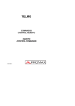
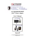
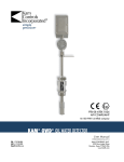
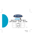
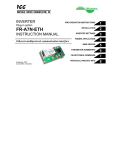
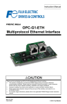
2257 North Penn Road
Hatfield, PA 19440
(215) 822-2171
[email protected]
www.simco.biz
INSTRUCTIONS
Operation/Maintenance
PerforMAX® IQ
Static Neutralizing System
SIMCO’s PerforMAX IQ is an intelligent air ionization system that
enables the user to be in charge of static electricity. It is designed to
efficiently neutralize electrostatic charges on films, paper, non-wovens
and fabric in web or sheet form. Due to its high output and range, the
PerforMAX IQ is also ideal for applications such as blow molding and
injection molding.
SECTION 1:
SECTION 2:
SECTION 3:
SECTION 4:
SECTION 5:
SECTION 6:
SECTION 7:
SECTION 8:
SECTION 9:
Description
Safety
Features
Specifications
Installation
Operation
Maintenance
Replacement Parts
Warranty
5200992 Rev F
(This page intentionally left blank)
2
5200992 Rev F
SECTION 1: Description
SIMCO’s PerforMAX IQ Static Neutralizing System consists of a high
voltage power supply, static neutralizing bar, and optional web monitor
and/or optional computer communication module. The PerforMAX IQ
static bar is available in three different types; tailored for high speed
processes, operating at a distance from the material or intermediate
(hybrid) applications. The PerforMAX IQ web monitor allows multiple
probes to measure web voltages and provide feedback to the system
enabling closed-loop operation of the static neutralizing process. The
PerforMAX IQ communication module provides the ability to remotely
monitor real time system performance and log operating data through a
computer interface.
The high voltage power supply module provides microprocessor
controlled high voltage DC output to the static bar. The high voltage
causes the ionizing pins on the static bar to generate positive and
negative ions. The electric field from the static charge on the material
being processed will attract opposite polarity ions from the static bar
causing the material to be neutralized. The excess ions will either
recombine in air or dissipate to ground.
The static neutralizing bar features current limiting at each individual ion
emitting pin to minimize the risk of hazardous electrical shock if the bar is
touched while in operation. This safety feature does not compromise the
PerforMAX IQ system’s ability to neutralize static charges. The emitter
pins are made of a special alloy to extend the longevity and sharpness of
the points, providing optimal performance of the static bar.
The PerforMAX IQ static bar is tailored to the application. Speed bars
are optimized to operate on high speed webs at distances of 50 to 230
millimeters [2 to 9 inches]. Hybrid bars operate at distances of 150 to
460 millimeters [6 to 18 inches] on webs where the web path is
somewhat variable. Distance bars are designed to operate from 300 to
760 millimeters [12 up to 30 inches] to the material. The variety of
PerforMAX IQ static bars offered allows the user to install the optimum
bar for their static neutralizing needs.
The PerforMAX IQ static bar has a plug-in style high voltage connector
for fast and easy installation. The connector features a pin that “tells” the
PerforMAX IQ power supply what type PerforMAX IQ bar is installed and
optimizes the power supply output for that type of bar.
The web monitor accepts the input from up to four remote web voltage
probes. When installed as part of the PerforMAX IQ system, the web
3
5200992 Rev F
monitor provides feedback on residual web voltages downstream of the
static neutralization bar and provides closed-loop control optimizing
system performance.
The communication module is designed as a port for an Anybus®
CompactCom module. This module provides interface with a wide
variety of standard industrial computer communication protocols allowing
easy integration of the PerforMAX IQ static neutralizing system with
existing networks. The communication module is also available without
the Anybus® port. These units are supplied with a USB adapter that
provides for connection to a personal computer and include software to
monitor and log data from the Performax IQ system.
All PerforMAX IQ optional modules use standard 8-conductor modular
cable and RJ-45 connectors for connection to the Performax IQ system..
They are supplied with 7 foot cable assemblies but longer custom cables
may be used.
Anybus® CompactCom is a registered trademark of HMS Industrial Networks.
4
5200992 Rev F
SECTION 2: Safety
SIMCO recommends that these instructions be read completely before
installation or operation is attempted. Failure to do so could result in
personal injury and/or damage to the equipment.
NOTE – Statements identified with NOTE indicate precautions
necessary to avoid potential equipment failure.
CAUTION – Statements identified with CAUTION indicate potential
safety hazards.
NOTE
This equipment must be correctly installed and properly
maintained. Adhere to the following notes for safe installation
and operation:
1. Read instruction manual before installing or operating
equipment.
2. Only qualified service personnel are to perform installation
and repairs.
3. All equipment must be properly grounded, including the
machine frame to which the equipment is mounted.
4. Disconnect input power to power supply before connecting
or disconnecting static neutralizing bars to the high voltage
power supply.
5. Do not operate system in close proximity to flammable
liquids.
CAUTION – This product is intended to be supplied by a Listed AC
Adapter or Power Unit marked "Class 2" or "LPS" and rated
output 24V
DC, 3.75A.
CAUTION – Electrical Shock Hazard
Disconnect input power to high voltage power supply before
connecting or disconnecting static neutralizing bar or
performing any maintenance to the system. Avoid touching
static neutralizing bar when power supply is energized.
CAUTION – Fire Hazard
Do not install or operate static neutralizing bar in close
proximity to any flammable liquids or solvents.
5
5200992 Rev F
SECTION 3: Features
· Three types of PerforMAX IQ static neutralizing bars are available to
suit the specific application.
· Static bar disconnect plug pre-installed on static bar cable for quick
and easy installation. Plug also identifies bar type to power supply
automating power supply set-up.
· Single momentary push-button calibration simplifies set-up.
· Ionization emitter points current limited to enhance operator safety.
· Ionization emitter points of special alloy to extend operating life of
emitter points.
· Continuous “T” slot at back of static bar and mounting brackets for
easy and flexible installation.
· Bar graph display on power supply indicates ionizing performance of
system.
· Indicators on power supply display status of neutralizing system,
power, service required and detection of system faults.
· Relay contact output “echoes” indicators on power supply for remote
sensing and alarm.
· Optional web monitor provides feedback on web charge downstream
of static bar and enables closed-loop control of ionization system.
· Web monitor allows for multiple probe installation.
· Optional computer interface allows for remote monitoring and logging
of the system’s performance.
6
5200992 Rev F
SECTION 4: Specifications
4.1 High Voltage Power Supply
Input Power:
24
VDC, 1.5A from AC adapter
Output Voltage:
BPS Basic Power Supply
+/-7kV “Speed Bar”
+/-9kV “Hybrid Bar”
+/-12kV “Distance Bar”
VLPS Voltage Limited Power Supply
+/-7kV “Speed Bar”
+/-8kV “Hybrid Bar”
+/-8kV “Distance Bar”
Dimensions:
202mmL x 123mmW x 106mmH
[7.95”L x 4.85”W x 4.17”H]
Weight:
1.94 kg [4.28 lb]
Max. Operating Temp: 43°C [110°F]
Housing:
Aluminum, black epoxy powder coated
High Voltage Connectors: 2 proprietary PerforMAX IQ plug-in outlets
4.2 Static Neutralizing Bar
Nominal Bar Length:
301 to 3961mm Overall Length [11.8” to 156”]
210 to 3870mm Effective Length [8.27” to 152”]
Profile Dimensions:
24mmW x 38mmH [.94”W x 1.50”H]
Weight:
1.2 g/mm [.07 lb/in.)
Max. Operating Temp: 80°C [176°F]
Max. Humidity:
70% RH, no dewing permissible
Housing:
Glass-fiber-reinforced polyester
HV Conduit:
Flexible nylon tubing, black
Emitter Material:
Proprietary alloy specially selected to extend life
7
5200992 Rev F
Emitter Spacing:
Speed Bar – 30mm [1.18”]
Hybrid Bar – 90mm [3.54”]
Distance Bar – 180mm [7.09”]
Operating Distance:
Speed Bar – 50mm to 230mm [2” to 9”]
Hybrid Bar – 150mm to 460mm [6” to 18”]
Distance Bar – 300mm to 760mm [12” to 30”]
Installation Hardware:
Plastic mounting brackets, metal perforated
strips and stainless steel hardware (screws,
washers, nuts).
4.3 AC Adapter
Type
“Universal” desktop
Input Power:
100 – 240VAC 50/60Hz input
(IEC 60320 C6 inlet)
Output:
24VDC, 3.75A maximum
Dimensions:
132mmL x 60mmW x 34mmH
5.19”L x 2.36”W x 1.34”H]
Weight:
0.45 kg [1.0 lb]
Housing:
Thermoplastic, black
4.4 Web Monitor
Input Power:
24VDC, 0.25A from PerforMAX IQ system
Probe Quantity:
Total 4 probes maximum
Dimensions:
202mmL x 123mmW x 106mmH
[7.95”L x 4.85”W x 4.17”H]
Weight:
1.12 kg [2.48 lb]
Max. Operating Temp: 43°C [110°F]
Housing:
Aluminum, black epoxy powder coated
8
5200992 Rev F
4.5 Web Probe
Operating Distance:
25mm [1”], 50mm [2”], 75mm [3”]
firmware selectable, default: 25mm [1”]
Installation Location:
Downstream of static bar
Input Power:
from PerforMAX IQ Web Monitor
Purge Connection:
¼” tube quick connect
Purge Flow:
0.14 m /h [5 CFH] clean, dry air
Dimensions:
110mmL x 35mmW x 37mmH
[4.33”L x 1.38”W x 1.46”H]
Weight:
0.22 kg [0.48 lb]
3
Max. Operating Temp: 43°C [110°F]
Housing:
Aluminum and Stainless Steel
Installation Hardware:
Metal perforated strips and stainless steel
hardware (screws, washers, nuts).
4.6 Communication Module
Input Power:
24VDC, 1.0A from AC adapter
Communication Module: Anybus® CompactCom, see Replacement
Parts / Additional Items section for protocols
available (units with Anybus®)
USB Adapter:
RS-485 isolated port (units without Anybus)
USB Compatibility: 1.0, 1.1, 2.0
Dimensions:
202mmL x 123mmW x 55mmH
[7.95”L x 4.85”W x 2.15”H]
Weight:
0.77 kg [1.70 lb]
Max. Operating Temp: 43°C [110°F]
Housing:
Aluminum, black epoxy powder coated
9
5200992 Rev F
SECTION 5: Installation
Figure 5.1 PerforMAX IQ Static Bar Installation
Figure 5.2 PerforMAX IQ Static Bar Bracket
10
5200992 Rev F
Figure 5.3 PerforMAX IQ High Voltage Connector
Figure 5.4 PerforMAX IQ Web Monitor Probe Installation
11
5200992 Rev F
Figure 5.5 PerforMAX IQ Web Monitor Probe Bracket
Figure 5.6 PerforMAX IQ Connections
(Bar and Power Supply)
12
5200992 Rev F
Figure 5.7 PerforMAX IQ Connections
(Bar, Power Supply and Web Monitor)
Figure 5.8 PerforMAX IQ Connections
(Bar, Power Supply, Web Monitor and Communication Module)
13
5200992 Rev F
Figure 5.9 PerforMAX IQ Connections
(Power Supply to Power Supply)
14
5200992 Rev F
Figure 5.10 PerforMAX IQ Power Supply Alarm Output Connections
Pin
Description
Pin
1
Remote on/off
optocoupler (-)
10
14
Remote on/off
optocoupler (+)
6
Description
Sensor Relay
(common)*
Sensor Relay (normal
closed)*
19
Sensor Relay (normally
open)*
11
Power Relay
(common)*
2
Clean Bar Relay
(common)*
3
Clean Bar Relay (norm
close)*
7
16
Clean Bar Relay (norm
open)*
20
Power Relay (normally
open)*
8
Fault Relay (common)*
4
Fault Relay (normally
closed)*
12
Power in (ground)**
17
Fault Relay (normally
open)*
24
Power in (ground)**
9
Bar On Relay
(common)*
13
Power in (+24VDC)**
5
Bar On Relay (normal
closed)*
25
Power in (+24VDC)**
18
Power Relay (normal
closed)*
Bar On Relay (normally
open)*
*30V 1A Rating on Contacts
**1.6A Rating, Connect pins 12 & 24 in parallel and 13 & 25 in parallel
15
5200992 Rev F
Remote On/Off
Disabled
Normally Off
Opto High = Unit ON
Opto Low = Unit OFF
Normally On
Opto High = Unit OFF
Opto Low = Unit ON
Jumper Position at J3 for Remote Control Operation
Figure 5.11 PerforMAX IQ Web Monitor Remote Output Connections
Pin
1
2
6
4
3
5
Description
Pin
Power in (+24VDC)
Power in (ground)
Power in (ground)
Alarm Relay (common)
Alarm Relay (normally closed)
Alarm Relay (normally open)
8
7
9
16
Description
Alarm Relay (common)
Alarm Relay (normally closed)
Alarm Relay (normally open)
5200992 Rev F
5.1 Initial Considerations
Installation starts with mounting of the static neutralizing bar. Static bars
are typically installed just ahead of where problems due to static are
occurring. The power supply is installed in a convenient location within
reach of the static bar high voltage cable and visible to the machine
operator. Web monitors (where used) are typically installed where
visible to the machine operator. The web monitor probes are supplied
with a generous amount of hook-up cable and are mounted downstream
of the static bar. Communication modules (where used) may be installed
at any convenient location and connected to the system using the
modular low voltage cable.
5.2 Mounting the Static Neutralizing Bar
CAUTION – Fire Hazard
Do not install or operate static neutralizing bar in close proximity to
any flammable liquids or solvents.
A. Determine location for mounting the static bar. The static bar will
typically be located just ahead of where problems due to static are
occurring. A static audit by a SIMCO representative can determine
the best location for the static bar.
B. The appropriate operating distance, “R” (see Static Bar Installation
diagram) for the PerforMAX static bar is in part determined by the
application:
Speed bars (emitter point spacing: 30mm) are mounted closer to
the web, 50 to 230 millimeters [2 to 9 inches] and may be installed in
more congested areas of the machine, however the web path should
be fixed for the speed bar. Optimum mounting distance for high
speed webs is 100mm [4 inches]. Speed bars can be identified by
an ion emitter to emitter spacing of 30mm [1.18 inches].
Hybrid bars (emitter point spacing: 90mm) are mounted at a
distance to the web, 150 to 460 millimeters [6 to 18 inches] and are
usually installed where the web path is relatively free of obstructions.
The benefit of hybrid bars is that they allow mounting where the web
path is variable. Hybrid bars can be identified by an ion emitter to
emitter spacing of 90mm [3.54 inches].
Distance bars (emitter point spacing: 180mm) are mounted at a
greater distance to the target surface, 300 to 760 millimeters [12 to
30 inches] and must be installed in areas free of obstructions.
17
5200992 Rev F
Operating at a greater range of distances makes distance bars best
suited for areas such as material roll wind-up applications. Distance
bars can be identified by an ion emitter to emitter spacing of 180mm
[7.09 inches].
PerforMAX bars should NOT be installed or operated at distances
less than the minimum distance specified for the particular bar.
The “free area” between the static bar and web should have
approximately equal height and width.
There should be NO grounded metal such as an idler roller
immediately behind the web on the far side from the static bar. The
area behind the static bar should be as free as possible from
grounded metal.
See Static Bar Installation diagram. The effectiveness of any static
bar is determined in part by the distance to and speed of the target.
If a static bar is not performing adequately at a given distance, it may
be necessary to reduce the operating distance accordingly.
C. The PerforMAX static bar includes blue plastic mounting brackets,
perforated metal strips and assorted hardware.
D. Slide the mounting brackets onto the “T” channel on the back of the
static bar.
E. The perforated strip may be installed on the mounting bracket at right
angle to the bar or parallel to the bar. The perforated strip may be
bent or twisted to suit the application and will hold its shape as
installed.
F. Once the static bar is loosely installed, tighten all hardware.
G. Install (2) set screws into the holes in the side of the mounting bracket
using the provided hex key wrench. The set screws engage the “T”
on the base of the bar securing it in place.
See Static Bar Bracket diagram.
5.3 Mounting the Power Supply
A. Locate power supply at a convenient place within reach of the static
bar high voltage cable and visible to the machine operator. Power for
18
5200992 Rev F
the AC adapter and an electrical ground connection must be
available.
B. Secure power supply to the mounting surface (commonly a machine
frame) using M5 or M4 [#10 or #8] hardware (not supplied).
C. Locate AC adapter at a convenient place within reach of the power
supply.
D. Install AC Adapter by cleaning back of adapter and mounting surface
with alcohol. Allow alcohol to dry. Secure AC adapter to mounting
surface with two self-adhesive mounting pads.
NOTE - Do not apply line voltage to the AC adapter until
installation is complete. Also ensure that all input power
switches are in the OFF (0) position.
5.4 Mounting the Web Monitor (optional)
A. Locate web monitor at a convenient place visible to the machine
operator and within reasonable distance to the power supply.
Standard modular cable (black) supplied with unit is 2.13 meters [7
feet] long, however longer cable (not supplied) may be used. .
Special cables fabricated for the web monitor must be 8-conductor
modular cables with RJ-45 connectors wired “crossover” (reference
color: black).
B. Secure web monitor to the mounting surface (commonly a machine
frame) using M5 or M4 [#10 or #8] hardware (not supplied).
C. Locate probe(s) at web, downstream of static bar (see Web Monitor
Probe installation diagram). In order to minimize undesirable
interaction between the static bar and probe; the distance between
the probe and static bar should be greater than the distance between
the static bar and web. Typically the probe will be located 0.3 meters
(12 inches) or greater distance from the static bar.
If multiple static bars are used in the PerforMAX IQ system with web
monitor, the bars must be used on the same web. In these cases, the
probe must be located downstream of the last static bar in the system.
D. The default probe mounting distance is 25mm [1”] from web. If static
charges are excessively high, it may be necessary to mount probe
50mm [2”] or 75mm [3”] from web. Operating distance calibration is
software selectable and may be set in the web monitor.
19
5200992 Rev F
The “free area” between the probe and web should have
approximately equal height and width.
There should be NO grounded metal immediately beneath the web on
the far side from the probe.
See Web Monitor Probe Installation diagram.
E. The PerforMAX web monitor probe includes perforated strips and
assorted hardware.
F. The probe may be mounted on the perforated strip with nuts and lock
washers included. The perforated strip may be bent or twisted to suit
the application and will hold its shape as installed. See Web Monitor
Probe Bracket diagram.
G. In dusty applications or applications with corrosive chemicals, purge
the probe. Connect ¼”OD plastic tubing to the quick connect fitting
on the side of the probe. Apply clean, dry air at a flow rate of 0.14
m3/h [5 CFH] to purge.
To regulate the clean, dry compressed air use a pressure regulator,
such as Norgren model R07-100-RGAA or equal with a flow meter
between the regulator and probe. The flow meter (with needle valve),
such as Key Instruments model MR 3A02-S-V-VT or equal, connects
to the probe. Set the pressure regulator to 34 kPa [5 psi] and adjust
the needle valve on the flow meter for 0.14 m3/h [5 CFH].
5.5 Mounting the Communication Module (optional)
A. Locate communication module at a convenient place within
reasonably close distance to the computer. Standard modular cable
(black) supplied with unit to connect the Communication Module to
the PerforMAX power supply is 2.13 meters [7 feet] long, however
longer cable (not supplied) may be used. Special cables fabricated
for the communication module must be 8-conductor modular cables
with RJ-45 connectors wired “crossover” (reference color: black).
To ensure communication between the communication module and
the computer, maximum recommended cable length between the
communication module and computer is 3 meters [10 feet] or less.
B. Secure communication module to the mounting surface (commonly a
machine frame) using M5 or M4 [#10 or #8] hardware (not supplied).
20
5200992 Rev F
C. Install AC Adapter by cleaning back of adapter and mounting surface
with alcohol. Allow alcohol to dry. Secure AC adapter to mounting
surface with two self-adhesive mounting pads.
D. Install USB Adapter (units without Anybus) by cleaning back of
adapter and mounting surface with alcohol. Allow alcohol to dry.
Secure USB adapter to mounting surface with self-adhesive mounting
pads.
5.6 Electrical Connections
A. Ground power supply by connecting ground lead between ground
terminal on flange of the power supply and a good electrical machine
ground.
Connect static bar(s) by plugging in high voltage connector on static
bar to HV1 or HV2 on power supply. Secure high voltage connector
with the (2) captive screws on the sides of the connector. Do not
over-tighten.
See Bar and Power Supply Connections diagram.
CAUTION – Shock Hazard
Do not connect static neutralizing bar with power supply
energized. Disconnect input power or switch power off before
connecting static bar.
NOTE – Failure to fully seat the high voltage connectors into the
power supply connectors may result in permanent damage to the
bar, cable or power supply.
The exposed pin on the connector “tells” the power supply what type
of PerforMAX IQ static bar is being connected and automatically sets
up the power supply for that type of bar.
Secure the high voltage cable from the static bar. Route the flexible
nylon conduit clear of moving machine parts and other wiring. Bends
in the conduit must not “kink”. Secure conduit using nylon wire ties
(not supplied).
B. Connect power supply alarm output (if used). The power supply
“Alarm Output” is a standard DB25 pin connector located on the end
of the PerforMAX IQ power supply. A recommend max distance of 3
meters [10 feet] or less is suggested.
21
5200992 Rev F
The power supply alarm output provides a variety of relay contact
outputs that echo the status of the power supply indicator lights. The
relay contacts are rated for a maximum of 1 A at 30 VDC.
See Power Supply Alarm Output Connections diagram.
The alarm output connector also provides a means of remote power
in. See section “I. Connect user supplied power” for more details.
B.1 Remote on/off Control
The “Alarm Output” connector also provides for remote on/off control
of the power supply. Remote on/off control is configured with a
jumper on a pin header on the main power supply circuit board. The
default configuration is with the remote control disabled. The remote
control can be configured “normally off” or “normally on” by the jumper
setting. See Jumper Position at J3 for Remote Control Operation
diagram. To access the jumper the cover will have to be removed
from the power supply. Disconnect all input power from the power
supply. Remove the six screws securing the cover and slowly and
carefully remove the cover.
There is a ribbon cable connecting the face label on the cover to the
main circuit board. Use care not to disconnect this cable. If the cable
becomes disconnected, lift the latches on the sides of the ribbon
cable connector, insert the ribbon cable fully into the connector and
press the latches back down.
Reposition the jumper to enable the remote control either “normally
on” or “normally off”, as desired as shown in the Jumper Position at J3
for Remote Control Operation diagram. Replace the cover and
secure with the six screws.
When operating a power supply with the remote control circuit, power
may be applied through the “Alarm Output” connector or the “Power
In” connector on the end panel. If the “Power In” connector on the
end panel is used, the “Power” switch must be set to the “On” (1)
position.
Remote control is established by applying 24 volts DC to the “Alarm
Output” connector pins as specified in the Power Supply Alarm Output
Connections diagram. The user applied 24 VDC drives a low current
optoisolator on the PerforMAX IQ power supply main circuit board,
turning the power supply on or off, depending on the configuration of
jumper J3.
22
5200992 Rev F
C. Ground web monitor by connecting ground lead between ground
terminal on mounting flange of unit case and a good electrical
machine ground.
Connect web monitor (if used). Use the 2.13 meter [7 foot] (black)
modular cable supplied with unit. A longer cable (not supplied) may
be used. Special cables fabricated for the web monitor must be 8conductor modular cables with RJ-45 connectors wired “crossover”
(reference color: black).
The modular cable plugs into either of the “WM COMM” (“RS-485”)
connectors on the web monitor and the “PS COMM 2” connector on
the power supply.
See Power Supply and Web Monitor Connections diagram.
The modular cable should not be run parallel with the static bar high
voltage cable. Route the modular cable clear of moving machine
parts and protect it from abrasion. Secure using nylon wire ties (not
supplied). Do not over tighten.
If there is an excess of modular cable, do not coil it in the vicinity of
the static bar high voltage cable. If possible, cut modular cable to
length and re-terminate using an RJ-45 connector installed with the
same “polarization” as connector removed (note orientation of rib on
one side of modular cable to modular connector).
D. Connect web monitor probe(s) (if used). The web monitor probe
wire should not be run parallel with the static bar high voltage cable.
Route the wire clear of moving machine parts and protect it from
abrasion. Secure using nylon wire ties (not supplied). Do not over
tighten. Cut wire to length and apply barrel connectors as per
instruction sheet included with probe. Connect probe to “SENSOR
INPUT” 1, 2, 3, or 4 and hand tighten barrel connector nut to secure.
NOTE – Do not plug AC adapter output into any web monitor
“SENSOR INPUT” connector.
Web monitor probe must be electrically grounded. If probe is installed
on non-conductive structural materials, install a separate ground lead,
connected to a good electrical machine ground, to the ground terminal
on the side of the probe.
See Power Supply and Web Monitor Connections diagram.
23
5200992 Rev F
E. Connect web monitor remote output (if used). The web monitor
“Remote” is a standard DB9 pin connector located on the end of the
PerforMAX IQ web monitor.
The web monitor remote output provides a relay contact output for the
web monitor alarm. If the user set alarm voltage value in the web
monitor is exceeded, the alarm relay is activated. The relay contacts
are rated for a maximum of 1A at 30VDC.
See Web Monitor Remote Output Connections diagram.
The remote connector also provides a means of remote power in.
Contact SIMCO for more details.
F. Connect communication module (if used). Use the 2.13 meter [7
foot] (black) modular cable supplied with unit. A longer cable (not
supplied) may be used. Special cables fabricated for the
communication module must be 8-conductor modular cables with RJ45 connectors wired “crossover” (reference color: black).
The modular cable plugs into the “CM COMM 2” connector on the
communication module and either “PS COMM 1” connector on power
supply.
See diagram for Power Supply and Communication Module
Connections.
The modular cable should not be run parallel with the static bar high
voltage cable. Route the modular cable clear of moving machine
parts and protect it from abrasion. Secure using nylon wire ties (not
supplied). Do not over tighten wire tie.
If there is an excess of modular cable, do not coil it in the vicinity of
the static bar high voltage cable. If possible, cut modular cable to
length and re-terminate using an RJ-45 connector installed with the
same “polarization” as connector removed (note orientation of rib on
one side of modular cable to modular connector).
Communication Modules with Anybus®; Connect the Anybus®
CompactCom module to the PLC, data polling device or computer
network using an appropriate network cable.
Communication Modules without Anybus provide for RS-485
communication on “CM COMM 1”. Connect the RS-485 Isolated Port
USB adapter into either of the “CM COMM 1” connectors on the
24
5200992 Rev F
communication module, then connect to your computer using any
standard USB–A to USB-B cable. A recommend max distance of 3
meters [10 feet] or less is suggested for interfacing on either “CM
COMM1” ports only.
G. Connect other Power Supplies (if used). PerforMAX IQ power
supplies can be connected together via a “data buss”. The data buss
allows one PerforMAX IQ computer communication module to serve
multiple PerforMAX IQ power supplies and feed the data from all
power supplies into the network. A total of 12 power supplies may be
chained together on one data buss. Special cables for the data buss
must be 8-conductor modular cables with RJ-45 connectors wired
“straight through” (reference color: white).
The modular cable plugs into either “PS COMM 1” connector on a
power supply and chains to the next power supply where it again
plugs into either “PS COMM 1” connector. See Power Supply to
Power Supply Connections diagram.
H. Connect AC Adapter (make sure “POWER” switch on power supply
is in the “OFF” (0) position). Route low voltage wire clear of moving
machine parts and protect it from abrasion. Secure using nylon wire
ties (not supplied). Do not over tighten. Insert barrel connector into
“POWER IN” connector on the power supply. Hand tighten barrel
connector nut to secure.
NOTE – Do not plug AC adapter output into any web monitor
“SENSOR INPUT” connector.
If a communication module is used it requires a separate AC
adapter. Connect AC adapter (make sure “POWER” switch on
communication module is in the “OFF” (0) position). Route low
voltage wire clear of moving machine parts and protect it from
abrasion. Secure using nylon wire ties (not supplied). Do not over
tighten. Insert barrel connector into “POWER IN” connector on the
communication module. Hand tighten barrel connector nut to secure.
Connect line voltage to input side of AC adapter. The AC adapter is a
universal input type that accepts line voltage from 100 to 240 VAC
50/60Hz. The AC adapter line voltage connector accepts a line cord
with an IEC 60320 C5 connector (supplied). The line cord also
provides electrical ground to the AC adapter. Check electrical ground
integrity in the line voltage receptacle used for the AC adapter. This
ground must not be defeated.
25
5200992 Rev F
I. Connect user supplied power (if used). In cases where the user does
not want to use the AC adapter but wants to supply 24VDC power to
the PerforMAX IQ system, user supplied 24VDC power may be
applied two ways.
The “Power In” connector on the end panel of the PerforMAX IQ
power supply may be used to supply power to the system. This
connector requires the use of a Switchcraft 760K barrel type power
plug. The plug should be wired +24VDC to center and common
(ground) to outer barrel. The common must be bonded to electrical
ground. Wired in this fashion, the “Power” switch on the end panel of
the power supply is in circuit. Where a communication module is
used, power will also have to be supplied through the “Power In”
connector on the end panel of the communication module.
The “Alarm Output” connector on the end panel of the PerforMAX IQ
power supply may be used to supply power to the system. This
connector requires the use of a standard DP25 connector. The
connector should be wired:
· +24VDC to pins 13 & 25
· Common (ground) to pins 12 & 24
To ensure current carrying capacity, two pins are used for each
connection. The common must be bonded to ground. Wired in this
fashion, the “Power” switch on the end panel of the power supply is
bypassed. See Power Supply Alarm Output Connections illustration.
Power supplied in the above fashion must have adequate current
available to power all components on the system (power supplies:
maximum 4A, communication modules: maximum 1A). Input power
should be appropriately fused for safety purposes.
SECTION 6: Operation
NOTE – Before switching on power supply; ensure units are
properly grounded and static bar & probes are properly installed.
6.1 Power Supply Indicators
Power: Lights (green) to indicate power is on and the PerforMAX IQ
system is ready to operate.
26
5200992 Rev F
Sensor: Lights (orange) to indicate if a web monitor is connected to
the system and active. When this indicator is lit, the system is in
closed-loop feedback and the web monitor is controlling the balance
of ionization.
Bar On: Lights (green) when static neutralizing bar is active.
Fault: Lights (red) to indicate faulty condition of static bar, power
supply or high voltage connections. Power will have to be turned off
to clear the fault. When fault is cleared and power is restored, the
fault light will be extinguished.
Clean Bar: Lights (yellow) to indicate need to clean static bar. Clean
Bar indicator may light with low ion output (dirt build-up on ion
emitters) or high output current (conductive contamination on face of
bar). See Maintenance section for static bar cleaning details.
Mode: The indicator next to the type of bar connected will light
(green). “Speed”, “Hybrid” or “Distance” will be indicated.
In cases where two different types of bars are connected, the system
will set for the safer of the two operating voltages and light the
corresponding Mode indicator.
The Mode indicators (along with the Clean Bar indicator) indicate the
Power Supply number during start-up of the power supply.
Output: The output indicators range from “Low” to “High” in 10 steps
(2-red, 3-yellow, 5-green) and light to indicate the system relative ion
output. The output will normally be in the high range. Low output
generally indicates the need to clean the static bar. See
Maintenance section for static bar cleaning details.
6.2 Power Supply Operators
Initial Calibration: Is a momentary switch located in the face label
above “Initial Calibration” on the label. Pressing the face label firmly
above “Initial Calibration” initiates the calibration sequence and sets
the relative nominal ion output for the system.
The Initial Calibration button is also used to change the Power
Supply number. This number is used in software to identify the
power supply in systems that contain multiple power supplies and
include a Communication Module.
27
5200992 Rev F
System Start-up:
A. Apply line voltage to the AC adapter.
B. Move the power supply “Power” switch to the “On” (1) position.
C. The power supply indicators will briefly self-test during which all
will light.
D. Immediately after the self-test, the power supply number (default:
01) will be briefly displayed.
E. After the power supply number displays, the power supply
indicators will settle to display the system status.
On new systems the output indicator will settle to display low output,
initial calibration must be performed.
F. If the system includes a web monitor, zero all sensors at this
time. Press the “Menu” button on the web monitor until the Zero
Sensor menu appears. Select YES and continue pressing the
“Menu” button until all sensor probes have been zeroed.
NOTE – Initial Calibration should be performed when the system
is first installed and may be performed after the static bar has
been cleaned and the system verified as operating correctly.
G. If the system is new, perform an Initial Calibration. The initial
calibration sets the relative nominal ion output for the system.
The initial calibration should only be performed on PerforMAX IQ
systems that are new or just cleaned and known to be in proper
working order.
During initial calibration the target to be neutralized (web, film, etc.)
may remain in place, but MUST NOT BE MOVING. If the web is
moving past the static bar (e.g. the machine is in operation) the
initial calibration may be faulty.
The system should be “on” and in the operating mode (not in startup self-test or power supply number display modes). Press the face
label on the power supply firmly above the words “Initial Calibration”.
This will initiate the calibration sequence and set the relative
nominal ion output for the system.
28
5200992 Rev F
During initial calibration the system output will be cycled and the
output indicator will sweep through its range several times. This will
occur twice, and then the indicators will settle to display the system
status. The indicated ion output will be high. The initial calibration
sequence takes less than one minute.
The initial calibration data is stored in non-volatile memory and used
on subsequent power ups.
6.3 Power Supply Number (Address)
Adjusting the Power Supply number is only necessary in systems
with multiple Power Supplies connected to a Communication
Module. Having multiple Power Supplies with the same Power
Supply number connected to a Communication Module is not
permitted.
A. Immediately after the self-test during which all indicators are lit,
the Power Supply number (default: 01) will be briefly displayed.
The Power Supply number is indicated by illuminating the LEDs
as per the following table. For example, the default Power
Supply number of “01” is indicated by illuminating the Speed
Mode LED only during this time.
B. If the Initial Calibration button is pressed immediately after the
self-test, the Power Supply number will increment by 1.
Repeatedly pressing the Initial Calibration button will continue to
increment the Power Supply number. The incrementing “wraps
around” (…09, 10, 11, 00, 01, 02…). Incrementing the Power
Supply number is indicated by flashing the Output LEDs. Once
the Output LEDs stop flashing and begin a sequenced lighting,
the Power Supply number can not be incremented; do not press
the Initial Calibration button at this time. When the Output
LEDs stop sequencing, the Initial Calibration button resumes the
calibration function.
29
5200992 Rev F
Power Supply Number Table
Power
Clean
Distance
Hybrid
Speed
Supply
Bar
Mode
Mode
Mode
Number
LED
LED
LED
LED
00
0
0
0
0
01
0
0
0
1
02
0
0
1
0
03
0
0
1
1
04
0
1
0
0
05
0
1
0
1
06
0
1
1
0
07
0
1
1
1
08
1
0
0
0
09
1
0
0
1
10
1
0
1
0
11
1
0
1
1
LED off = 0. LED on = 1.
Adjusting the Power Supply number is typically a “one time”
operation performed during the set-up of systems with multiple
Power Supplies and a Communication Module.
6.4 Static Bar Operation
A. Operation normally requires only occasional checking of the
system indicators on the power supply.
B. Anticipated changes in the system indicators include a reduction
of output over time. This may occur over several weeks and
ultimately cause the “Clean Bar” indicator to light. Regular
maintenance will typically prevent activation of the indicator.
C. Unanticipated changes in the system indicators include
activation of the Fault indicator. This would indicate faulty
condition of static bar, power supply or high voltage connections.
See Troubleshooting section.
30
5200992 Rev F
6.5 Web Monitor Operation (optional)
A. Switch the “Power” switch on web monitor to the “On” (1)
position.
B. The web monitor display will briefly display its firmware revision
level and then will begin communications with the PerforMAX IQ
system. Communication will be indicated by a flickering of the
(green) “Remote Communications Status” indicator on the web
monitor.
The power supply will indicate use of the web monitor by lighting the
“Sensor” indicator on the face of the power supply.
If the system is new, it may be necessary to change the Sensor
Spacing Distance and/or Feedback status in the web monitor control
box to agree with the actual installed sensor configuration. See
Sensor Spacing Distance / Feedback below.
C. During operation, the web monitor will display the web static
charge, in kilovolts, for each sensor. If no sensor is connected, it
will display “no sensor”.
D. The web static charge value is used by the PerforMAX IQ power
supply to provide closed-loop feedback. The power supply
adjusts its operation to null the web static charge value,
neutralizing the static charge. If multiple probes are used, the
web static charge value from all probes will be averaged.
E. The operating parameters for the web monitor may be set at any
time using the “Menu” and up (+) arrow or down (-) arrow buttons
on the face label of the web monitor.
Sensor Spacing Distance (default: 25mm [1”])
Allows adjustment of the distance between the web and the
sensor probe. Adjusting the sensor spacing distance allows for
calibrated operation at one of three distances: 25mm [1”], 50mm
[2”] and 75mm [3”]. The web monitor compensates for each
sensor probe individually. The sensor spacing distance may be
set for each individual probe.
Zero Sensor (default: no)
Used to null out any differences between the web monitor and
sensor probe. These differences can also be caused by sensor
probe wire re-termination. The sensor is typically zeroed (YES)
31
5200992 Rev F
on new installations or modified installations. Zeroing the sensor
matches the sensor probe to the web monitor.
Used for Feedback? (default: yes)
Allows setting sensor feedback status (YES/NO). Sensors with a
feedback status of YES are used by the PerforMAX IQ power
supply for closed loop feedback control of ionization. Sensors
with a feedback status of NO provide a web voltage value for
monitoring only.
Alarm Voltage Level (default: 5kV)
Allows adjustment of the alarm voltage level. If any probe
measures above this user set value, the web monitor will go into
alarm. Alarm relay contacts are available through the “Remote”
connector on the end of the web monitor.
Slave Address (default: 1)
Allows setting of address for communication. Slave addresses
of 1 thru 4 are available.
Set Unit to Factory Defaults (default: no)
YES clears all changes for all sensors in the web monitor and
resets all changes back to the factory default settings.
F. The web monitor controls (buttons on the face label) may be
locked or unlocked by pressing the up (+) and down (-) buttons
at the same time and holding them down for approximately 2
seconds. Locked web monitor controls are indicated by a lit
(red) “Front Panel Controls Locked” indicator.
G. The recommended web monitor calibration interval is one year,
contact Simco for more information.
6.6 Communication Module Operation (optional)
A. Move the communication module “Power” switch to the “On” (1)
position. The communication module will include a full
instruction manual (5201059).
B. The Anybus® CompactCom module will be powered and
communicating with the PerforMAX system.
C. The Anybus® CompactCom module typically has built-in
indicator lights for power and communication. A SIMCO
software technical specification specific to the Anybus® network
32
5200992 Rev F
interface chosen is supplied with the communication module.
See Anybus HMS Industrial Networks (www.anybus.com) for
more information specific to the Anybus® module.
D. Units without Anybus are supplied with an RS-485 isolated port
USB adapter. The USB adapter is powered by the personal
computer and communicates with the PerforMAX IQ system.
E. Communication modules without Anybus are supplied with
PerforMAX IQ interface software for a personal computer and
the software user manual (5200993). See B&B Electronics
Manufacturing (www.bb-elec.com) for more information specific
to the USB adapter.
SECTION 7: Maintenance
NOTE – Only qualified service personnel are to perform
maintenance tasks.
NOTE – Never use hard or sharp objects to scrape ionization
emitter points.
CAUTION – Electrical Shock Hazard
Turn off power supply before cleaning bar or performing any
maintenance on the system.
CAUTION – Fire Hazard
Do not turn on power supply with any trace of alcohol or mineral
spirits on the equipment.
The accumulation of contamination on the ionization emitter points and
static bar surfaces will reduce neutralizing efficiency of the bar, therefore
it is recommended that maintenance of the system be performed when
the Clean Bar indicator on the display module illuminates or every three
weeks, whichever comes first. Dirty environments may require more
frequent cleaning. Maintenance should be performed by qualified
service personnel only.
7.1 Cleaning the Static Bar
A clean brush with nylon bristles should be used to keep the
ionization emitter points of the static bar clean. Periodic use of the
brush will prevent deposits from accumulating on the points. The
emitter points must remain sharp for optimum operation.
33
5200992 Rev F
NOTE – Do not scrape points with any hard or sharp object that
may damage points.
A. Turn off power supply.
B. Remove dirt particles deposited on the static bar with a dry, stiff
nylon bristle brush.
C. Blow off the static bar with clean, dry compressed air.
D. Remove resistant coatings deposited on static bar by wiping with
isopropyl alcohol or mineral spirits applied to a clean cloth.
Apply isopropyl alcohol or mineral spirits to a stiff nylon bristle
brush and thoroughly scrub the ionization emitter channels of the
bar.
E. Blow static bar dry with clean, dry compressed air and ensure
the bar is completely dry before re-applying power to the bar.
NOTE – Do not soak static bar or related components in alcohol or
mineral spirits. Do not use harsh solvents such as lacquer thinner,
naphtha or acetone. They will damage the bar housing and epoxy.
CAUTION – Fire Hazard
Do not turn on power supply with any trace of alcohol or mineral
spirits on the equipment. Allow all alcohol or mineral spirits to
evaporate.
7.2 Troubleshooting
CAUTION – Electrical Shock Hazard
Do not troubleshoot high voltage components with power supply
energized. Disconnect input power or switch power off before
troubleshooting. Troubleshooting must be performed by a qualified
service person.
34
5200992 Rev F
PROBLEM
Power indicator NOT
illuminated.
Sensor indicator NOT
illuminated.
Bar ON indicator NOT
illuminated.
Fault indicator
illuminated.
CAUSE
SOLUTION
Power not on at
power supply.
Turn on Power switch
on end of power
supply case.
Poor electrical
connections.
Check input power
connections, both
24VDC and line
voltage.
Defective AC
adapter.
Replace AC adapter.
W eb monitor not
installed.
Sensor indicator only
illuminates if optional
web monitor is
installed.
Poor electrical
connections.
Check connections of
modular cable at
power supply and
web monitor.
Power not on at
web monitor.
Turn on Power switch
on end of web monitor
case.
No static bar
connected.
Install static bar and
connect to power
supply.
Static bar high
voltage connector
is not connected.
Turn off power,
reconnect static bar
and secure plug with
captive screws.
Static bar high
voltage connector
missing bar type
sense pin.
Replace static bar
high voltage
connector plug.
Static bar
mounted too
close to grounded
metal.
Separate static bar
from grounded metal.
Damage to high
voltage
connector.
Replace high voltage
connector.
Damage to high
voltage cable.
Replace static bar.
Faulty HV module
inside power
supply
Replace high voltage
module.
35
5200992 Rev F
PROBLEM
Clean Bar indicator
illuminated.
W eb Monitor Remote
Communication Status
indicator NOT flickering.
W eb Monitor display
scrambled.
Communications Module
not working.
CAUSE
SOLUTION
Process material
fouling static bar
ion emitters.
Remove process
material from static
bar.
Dirt build-up on
ion emitters or
conductive
contamination on
face of bar.
Clean ion emitters
and static bar. See
Maintenance section
for details.
Poor electrical
connections.
Check connections of
modular cable at
power supply and
web monitor.
Incorrectly wired
modular cable
(check against
cable illustrations
in Installation
section).
Replace modular
cable.
Display
microprocessor
“locked up”.
Turn power switch on
end of web monitor
case off, then back
on, to reset display
microprocessor.
Power not on at
communication
module.
Turn on Power switch
on end of
communication
module case.
Poor electrical
connections.
Check connections of
modular cable at
power supply and
web monitor.
Incorrectly wired
modular cable
(check against
cable illustrations
in Installation
section).
Replace modular
cable.
36
5200992 Rev F
SECTION 8: Replacement Parts
Part Description
Part Number
BPS Basic Power Supply (no AC adapter)
(With AC adapter, 100/120VAC Jpn. / N. Amer. Cord)
(With AC adapter, 230VAC N. Amer. Cord)
(With AC adapter, 230VAC European Cord)
(With AC adapter, 230VAC UK Cord)
4011725
4011726
4011727
4012041
4012042
VLPS Voltage Limited Power Supply (no AC adapter)
(With AC adapter, 100/120VAC Jpn. / N. Amer. Cord)
(With AC adapter, 230VAC N. Amer. Cord)
(With AC adapter, 230VAC European Cord)
(With AC adapter, 230VAC UK Cord)
4012390
4012391
4012392
4012393
4012394
AC Adapter (100-240VAC input)
4108774
Line Cord,
Line Cord,
Line Cord,
Line Cord,
4520778
4590779
4590780
4590781
North American / Japan 120/100VAC
North American 230VAC
Continental Europe 230VAC
United Kingdom 230VAC
Web Monitor (with 1 probe)
Web Monitor Probe
Probe Mounting Kit
4011468
4011544
5051470
Communication Module w/Anybus (no AC adapter)
(With AC adapter, 100/120VAC Jpn. / N. Amer. Cord)
(With AC adapter, 230VAC N. Amer. Cord)
(With AC adapter, 230VAC European Cord)
(With AC adapter, 230VAC UK Cord)
4011592
4011855
4011856
4012043
4012044
Communication Module w/o Anybus (no AC adapter)
(With AC adapter, 100/120VAC Jpn. / N. Amer. Cord)
(With AC adapter, 230VAC N. Amer. Cord)
(With AC adapter, 230VAC European Cord)
(With AC adapter, 230VAC UK Cord)
4011852
4011857
4011858
4012045
4012046
37
5200992 Rev F
Part Description
Part Number
PerforMAX IQ Communication Software
RS-485 Isolated Port to USB Adapter Kit
5200994
5051508
Anybus EtherNet/IP IT AB6214 module kit
Anybus Profibus DPV1 AB6200 module kit
Anybus Modbus-RTU AB6203 module kit
5051542
5051543
5051550
Modular Cable (8-conductor, crossover wired, RJ-45) for
use between PerforMAX IQ power supply and web
monitor or communication module “CM COMM2”.
0.91 meter [3 foot] black
2.13 meter [7 foot] black
4.27 meter [14 foot] black
7.62 meter [25 foot] black
4520785
4520786
4520787
4520784
Modular Cable (8-conductor, straight through wired, RJ45) for use between PerforMAX IQ power supply and
PerforMAX IQ power supply only.
0.91 meter [3 foot] white
2.13 meter [7 foot] white
4.27 meter [14 foot] white
7.62 meter [25 foot] white
4520788
4520789
4520791
4520792
PerforMAX IQ Bar Mounting Bracket Kit
5051455
Static Bar Cleaning Brush
4670204
38
5200992 Rev F
SECTION 9: Warranty
This product has been carefully tested at the factory and is warranted to
be free from any defects in materials or workmanship. Simco Industrial
Static Control will, under this warranty, repair or replace any equipment
which proves, upon our examination, to have become defective within
one year from the date of purchase.
The equipment being returned under warranty should be shipped by the
purchaser to:
SIMCO Industrial Static Control
2257 North Penn Road
Hatfield, PA 19440
With transportation prepaid and insured for its replacement cost. Prior to
returning any goods for any reason, contact SIMCO Industrial Static
Control Customer Service at 215-822-6401 for a Return Authorization
Number (RMA). This number must accompany all returned items.
This warranty does not apply when the equipment has been tampered
with, misused, improperly installed, altered, has received damage
through abuse, carelessness, accident, connection to improper line
voltage, or has been serviced by anyone other than an authorized factory
representative.
The warranty does not apply when SIMCO Industrial Static Control parts
and equipment have been energized by other than the appropriate
SIMCO Industrial Static Control power supply or generator, or when a
SIMCO Industrial Static Control power supply or generator has been
used to energize other than SIMCO Industrial Static Control parts and
equipment. SIMCO Industrial Static Control makes no warranty,
expressed or implied, nor accepts any obligation, liabilities, or
responsibility in connection with the use of this product other than the
repair or replacement of parts stated herein.
39
5200992 Rev F
2257 North Penn Road
Hatfield, PA 19440
(215) 822-2171
www.simco.biz
[email protected]
40
5200992 Rev F