1
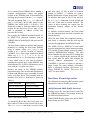
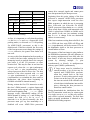
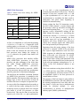
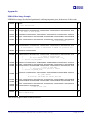
Engineer-to-Engineer Note a EE-56 Technical notes on using Analog Devices DSPs, processors and development tools Visit our Web resources http://www.analog.com/ee-notes and http://www.analog.com/processors or e-mail [email protected] or [email protected] for technical support. Tips and Tricks on SHARC® EPROM and Host Boot Loader Contributed by Stefan Hacker and Jeyanthi Jegadeesan Introduction After creating SHARC® processor application code and verifying it in simulation or emulation, a final task is to create a boot image for an EPROM or host processor. Though this is easy using the VisualDSP++® tools, some users want to add specific functionality to the boot loader or create their own boot loader. This document discusses the output of the elfloader tool and the arrangement of the data in the boot image. It shows where to add changes to modify boot loaders to adapt to different host processor widths or types. Boot Loading After reset, SHARC processors are configured, by default, to load 256 words of 48-bit width (instruction size) by DMA. DMA is configured, based on the boot mode selected during reset. ADSP-2106x, ADSP-2116x, ADSP-21367, ADSP-21368, ADSP-21369, and ADSP-2137x processors support booting through EPROM/flash connected to the external port of the processor. ADSP-2126x, ADSP-21362, ADSP-21363, ADSP-21364, ADSP-21365, and ADSP-21366 processors do not have an external port. The parallel port on these processors supports booting from EPROM/flash. Rev 3 – March 6, 2007 L Hereafter, we will representatively refer to the ADSP-21367, ADSP-21368, and ADSP-21369 processors as ADSP21368 processors. Similarly, we will refer to the ADSP-21362, ADSP-21363, ADSP-21364, ADSP-21365, and ADSP21366 as ADSP-21362 processors Table 1 shows the DMA channels and corresponding interrupt sources used by different SHARC processors for EPROM/PROM boot loading. Processor DMA IVT location ADSP-2106x DMA channel 6 0x40 ADSP-21065L DMA channel 8 0x40 ADSP-2116x DMA channel 10 0x50 ADSP-2126x Parallel port DMA 0x50 ADSP-21362 Parallel port DMA 0x50 ADSP-21368 ADSP-2137x External port DMA channel 0 0x50 Table 1. DMA channels for EPROM/flash booting Differences between external port and parallel port include: In parallel port, the address bus and data bus are multiplexed. In external port, the data bus and address bus are separate. The parallel port (unlike external ports) cannot have direct core access. Data must be read through DMA controller. Copyright 1999-2007, Analog Devices, Inc. All rights reserved. Analog Devices assumes no responsibility for customer product design or the use or application of customers’ products or for any infringements of patents or rights of others which may result from Analog Devices assistance. All trademarks and logos are property of their respective holders. Information furnished by Analog Devices applications and development tools engineers is believed to be accurate and reliable, however no responsibility is assumed by Analog Devices regarding technical accuracy and topicality of the content provided in Analog Devices Engineer-to-Engineer Notes. a Table 2, Table 3, Table 4, and Table 5 show DMA settings for EPROM booting. Numbers printed in italics are not initialized but are assumed by the DMA engine. Since user application code is far larger than 256 words, a boot kernel ensures that the complete user application code and data is loaded into the internal memory spaces of the SHARC processor. Additionally, external memories and data ports are initialized by the kernel. ADSP-21060/1/2 ADSP-21065L DMAC Register DMAC6=0x2A1 DMAC0=0x2A 1 II6 IIEP0 0x20000 0x8000 IM6 IMEP0 0x1 0x1 C6 CEP0 0x100 0x100 EI6* EIEP0* 0x40 0000 0x80 0000 EM6 EMEP0 0x1 0x1 EC6 ECEP0 0x600 0x600 0x20040 0x8040 IVT Location Table 2. EPROM boot setting with BSO bit set for ADSP-2106x processors DMAC Register ADSP-21160 ADSP-21161 DMAC10= DMAC10= 0x4A1 0x4A1 II10 IIEP0 0x40000 0x40000 IM10 IMEP0 0x1 0x1 C10 CEP0 0x100 0x100 EI10* EIEP0* 0x80 0000 0x80 0000 EM10 EMEP0 0x1 0x1 EC10 ECEP0 0x600 0x600 0x40050 0x40050 IVT Location * BMS space Table 3. EPROM boot setting with BSO bit set for ADSP-2116x processors ADSP-2126x ADSP-21362 PPCTL Register PPCTL=0x16F PPCTL=0x412F IIPP 0x0 (offset from normal word start address 0x80000) 0x0 (offset from normal word start address 0x90000) IMPP 0x1 0x1 ICPP 0x180 0x180 EIPP 0x0 0x0 EMPP 0x1 0x1 ECPP 0x600 0x600 IVT Location 0x80050 0x90050 Table 4. PROM boot setting for ADSP-2126x and ADSP-21362 processors ADSP-21368 ADSP-2137x DMAC Register AMICTL0=0x5C1 AMICTL0=0x5C1 IIEP0 0x90000 0x90000 IMEP0 0x1 0x1 ICEP0 0x180 0x180 EIEP0 0x40 00000 0x40 00000 EMEP0 0x1 0x1 CPEP0 0x180 0x180 IVT Location 0x90050 0x90050 Table 5. EPROM boot setting for ADSP-21368 and ADSP-2137x processors Boot Loader Names and 065l_prom.asm are the source files for ADSP-2106x PROM-based loaders. 060_prom.asm 16x_prom.asm, 26x_prom.asm, 36x_prom.asm, 369_prom.asm, and 37x_prom.asm are the source files that correspond to the ADSP-2116x, ADSP-2126x, ADSP-21362, ADSP-21368, and ADSP-2137x processors, respectively. Tips and Tricks on SHARC® EPROM and Host Boot Loader (EE-56) Page 2 of 15 a and 065l_host.asm are the source files for the ADSP-2106x host-based boot loader. 060_host.asm 160_host.asm and 161_host.asm are the source files that correspond to the ADSP-2116x processors. Depending on the selected processor and the boot loading type, the corresponding boot kernel is loaded into seg_ldr at reset. The corresponding Linker Description File is named with the processor name, such as x6x_ldr.ldf. These source files are located in the <install_path>\21K\LDR subdirectory within the VisualDSP++ tools. Boot Kernel Structure Each kernel begins by defining macros for the various IOP registers used in the code and is followed by a table containing the interrupt vectors (up to and including the DMA interrupt aligned to the external port buffer 0 (EP0I) or parallel port interrupt). Most of these highpriority interrupts are not necessary for the operation of the boot loader and are filled with NOP or RTI instructions. The only interrupts used by the kernel are the reset interrupt and the external port or parallel port interrupt. The EP0I ___lib_RSTI interrupt is available at the offset 0x04-0x07 for all processors. The EP0I interrupt ___lib_EP0I is available at offset 0x40-0x43 for ADSP-2106x and ADSP-2116x processors. The parallel port interrupt ___lib_PPI is available at offset 0x50-0x53 for ADSP-2126x and ADSP21362 processors. For ADSP-21368 and ADSP2137x processors, the external port interrupt ___lib_EP0I is available at offset 0x50-0x53. ADSP-2106x and ADSP-2116x Boot Kernel Structure Start_loader Initializes some required registers. For EPROM booting, determines the processor ID of the processor in a multiprocessor environment. Load_memory Starts to parse the information from the boot source and copies it into the required memory location or clears not pre placed memory segments. final_init Swaps out the boot kernel and replaces it with the user application code. read_PROM_word Sets up the new DMA transfer to collect a new 48-bit word The PROM and host boot kernels for ADSP2106x and ADSP-2116x processors include the four sections listed above. For ADSP-21161N and ADSP-21065L processors, the initialization of the SDRAM should be enabled when the user application uses SDRAM to store code and data. ADSP-2126x and ADSP-21362 Boot Kernel Structure Host booting is not supported on ADSP-2126x and ADSP-21362 processors. The boot kernel begins by initializing the control registers required for downloading the boot image into the internal memory. The boot kernel starts by doing the following initializations: Enables the global interrupts. Initializes the parallel port control and SYSCTL registers. Initialize the DAG registers. Enable parallel port interrupt. The boot kernel available for the PROM boot on these processors has the following sections. Beginning from the start_loader label, the kernel code can be divided into four main sections: Tips and Tricks on SHARC® EPROM and Host Boot Loader (EE-56) Page 3 of 15 a READ_BOOT_INFO USER_INIT The section reads three normal words using parallel port DMA. It checks the tag and jumps to respective section to initialize the boot data. You can initialize external port control and other registers in this section. You can add code in this section. Ensure that the size of the boot kernel does not exceed 256 instructions. USER_INIT The user can initialize parallel port control and other registers in this section. READ_THREEx32 This section reads three normal words and stores them in scratch locations 0x80003/0x98003, 0x80004/0x98004, and 0x80005/0x98005. READ_ONEx32 This section reads one normal word and stores it at location 0x80003/0x98003. final_init After the application has been downloaded completely, the boot kernel replaces itself with interrupt vectors in this section. ADSP-21368 and ADSP-2137x Processors The boot loader does the following: Calls the user_init section, in which the user initialization code exists. Clears all interrupt registers, initializes external port0 interrupt, and enables global interrupts. Initializes DAG registers and saves initial settings of the SYSCTL register. final_init After the application is downloaded completely, the boot kernel replaces itself with interrupt vectors in this section READ_THREEx32 This section reads three normal words and stores them in scratch locations 0x98003, 0x98004, and 0x98005 READ_ONEx32 This section reads one normal word and stores it at location 0x98003 x50_EP0I_ISR External port interrupt vector MULTI_PROC This section reads the processor ID from SYSTAT and changes the offset address to the application code, based on the processor ID. This section is useful in a multiprocessor system where multiple applications can be downloaded from a single flash memory across all the processors in the multiprocessor system. This section applies only to ADSP-21368 processors. L The boot kernel is divided into the following sections: READ_BOOT_INFO This section: Reads three or one normal words using external port DMA and places them in scratch location starting at 0x98003. This data is later used to initialize the boot data at the required address. Checks the tag and jumps to the respective section to initialize the boot data. Tips and Tricks on SHARC® EPROM and Host Boot Loader (EE-56) If external SDRAM is connected, uncomment #define SDRAM in the user_init section. Failure to do so may not copy correct values during boot to SDRAM. Also, if the SDRAM used is different from the SDRAM on the EZKIT Lite® board, the initialization values must be changed accordingly in the user_init section. Page 4 of 15 a EPROM Boot Kernel Operation The following sections describe EPROM boot kernel operation for various SHARC processors. ADSP-2106x, ADSP-21065L, and ADSP-2116x Processors After reset, the core processor is held in an IDLE mode until the first 256 words (each 48 bits wide), have been loaded by DMA into internal memory. The External Port DMA interrupt for EP0I is activated upon the completion of the DMA transfer. The core processor starts execution of the just-loaded boot kernel by branching to the vector interrupt location for EP0I. In ___lib_EP0I, the DMA control register setting is stored in R2 for later restoration, and the DMA channel is disabled temporarily by clearing the DMA enable bit in the control register. Having completed the IRQ service, the core processor starts up the loader program. Beginning from the start of execution, some required registers are initialized. This is a good place to start up external memories like SDRAM on ADSP-21065L processors or to set wait states and wait modes. If there is a user_init section in the boot kernel, the SDRAM and asynchronous memory interface (AMI) control initializations can be done in the user_init section. /BMS is deactivated, and normal external memory selects are activated by clearing the BSO bit in the SYSCON register. Three copies of SYSCON are used in the program: one that contains the original value of SYSCON, one that contains SYSCON with the BSO bit set so that an ADSP-2106x processor can gain access to the boot EPROM, and a third with the BSO bit cleared. When BSO=1, the EPROM packing mode bits in the DMACx control register are ignored and 8-to-48-bit packing is forced. For ADSP-21065L processors, a 32-bitwide system bus is assumed. L Note that 8-to-48-bit packing is available only on ADSP-2106x processors during DMA reads from /BMS space with the BSO bit set. When one of the external port DMA channels is being used in conjunction with the BSO bit, none of the other three channels may be used. When BSO=1, /BMS is not asserted by a core processor access, only during a DMA transfer. This allows your bootstrap program (run by the ADSP-2106x core) to perform other external accesses to nonboot memory. The IMASK register is set finally to allow the EP0I interrupt and the MODE1 register is set to enable interrupts and nesting. Having completed the setup, the DMA engine on ADSP-2106x processors is used to collect 48-bit words from the EPROM. As an external boot EPROM allows starting a complete multiprocessor cluster, the proper section in the EPROM must be determined by checking the processor ID in the SYSTAT register. The code beginning from the get_addr label will parse a seven-entry 48-bit table stored in the EPROM (hex offset 0x600 = 6*0x100 = 256 instruction words) to find the start address of the boot section for this processor. Every entry of the table is formatted as address (32-bit) and processor ID (16-bit). For example, the readback 0x8002062A0001 for an ADSP-21065L processor translates into an EPROM offset of 0x8002062A and processor ID of 0x0001. Having determined the offset, the DMAC6/DMAC0 control register is set to 0x2A1, DMAC6 is set to 0x4A1 (ADSP-2116x processors), and DMA parameters are set up to read data word-by-word beginning from the starting address of the boot section corresponding to the processor ID in the boot EPROM. Each 48-bit word is transferred into address 0x20004 (ADSP-2106x processors), 0x8004 (ADSP-21065L processors), or 0x40004 (ADSP-2116x processors) for dispatching. Because the image in the EPROM contains Tips and Tricks on SHARC® EPROM and Host Boot Loader (EE-56) Page 5 of 15 a program memory code sections and data memory sections with different sizes, a preamble is stored before each boot block. The preamble with the attached boot block is formatted as shown in Table 6. 0x0000 0000 DDDD D (data type tag) 0xAAAA AAAA LLLL A (address), L (length) 0xBOOT BOOT BOOT Boot data : : 0xBOOT BOOT BOOT Boot data Table 6. Boot section header Each initialization block is identified by a 16-bit tag (Table 7) placed before the block. Each type of initialization has a unique tag number. Tag Number Initialization Type 0 0x0 FINAL_INIT 1 0x1 ZERO_DM16 2 0x2 ZERO_DM32 3 0x3 ZERO_DM40 4 0x4 INIT_DM16 5 0x5 INIT_DM32 6 0x6 INIT_DM40 7 0x7 ZERO_PM16 8 0x8 ZERO_PM32 9 0x9 ZERO_PM40 10 0xA ZERO_PM48 11 0xB INIT_PM16 12 0xC INIT_PM32 13 0xD INIT_PM40 14 0xE INIT_PM48 Table 7. Section header types The boot kernel initializes internal and external memories by reading the data from EPROM using a routine called Read_Prom_Word and writing it to a specific location of memory 0x20004 (ADSP-2106x processors), 0x8004 (ADSP-21065L processors), or 0x40004 (ADSP2116x processors). For a zero-valued format data block whose tag is 1, 2, 3, 7, 8, 9, or 10, an initialization of 16- or 32-bit memory is done in a loop, which writes a zero value to memory, reducing the required space in the EPROM. Any initialization of 40- or 48-bit PM memory uses a write with the PX register set to zero. For a non-zero format data block whose tag is 4, 5, 6, 11, 12, 13, or 14, the kernel enters a loop which reads one 48-bit word from EPROM and writes the appropriate width value to memory. This loop is repeated once for each word being initialized. When the boot loader has completed parsing a boot block, it continues with the next tag and executes the appropriate initialization routine until the kernel reaches the FINAL_INIT (0x0) boot tag. In the final initialization stage, the kernel loads the first 256 words of the target executable file and overwrites itself. When the loader detects the tag, it reads the next 48-bit word. This word indicates the instruction to be located at 0x20004 (ADSP-2106x processors), 0x8004 (ADSP21065L processors), or 0x40004 (ADSP-2116x processors) when the loading is close to being completed. This instruction is saved into the 48bit PX register so that the boot loader can now finish initializing internal memory. The kernel requires an RTI instruction at address 0x20004 (ADSP-2106x processors), 0x8004 (ADSP21065L processors), or 0x40004 (ADSP-2116x processors), which is temporarily placed, because an EP0 interrupt is generated when the initialization is completed. The R9 register is loaded with 0xBDB0000, which contains the encoded instruction PM(0,I8)=PX. This writes the desired customer instruction over the RTI used by the boot kernel with I8 pointing to 0x20004 (ADSP-2106x processors), 0x8004 (ADSP-21065 processors), or 0x40004 (ADSP2116x processors). Tips and Tricks on SHARC® EPROM and Host Boot Loader (EE-56) Page 6 of 15 a Before the DMA sequence is initiated, the core processor is trapped in a pseudo loop by issuing: DO ___lib_RSTI UNTIL EQ; FLUSH CACHE; R0=0x20004; /* 0x8004 on ‘65l 0x40004 on ADSP-2116x*/ PCSTK=R0; <DMA init> /* some code here */ IDLE; and manually adding the return address 0x20004, 0x8004, or 0x40004 onto the stack. The loop terminates on an equal condition. Because the code will be overwritten by the DMA sequence, it is necessary to invalidate the cache with a FLUSH CACHE instruction. The last 256 48-bit words are loaded into memory over the boot loader while the core processor is idling. Upon completion, the RTI is executed at address 0x20040, 0x8040, or 0x40040, returning the core processor to address (0x20004, 0x8004, or 0x40004) so that the next instruction to be carried out is filled with following instruction line: R0=R0-R0,DM(I4,M5)=R9,PM(I12,M13)=R11 which is read from the EPROM. This instruction clears the loop condition (r0=r0-r0), puts PM(0,I8)=PX (held in R9) into 0x20004, 0x8004, or 0x40004, and sets SYSCON back to the original value. At loop termination of the loop, the program sequencer is set back to 0x20004, 0x8004, or 0x40004. The PX write exchanges the previously placed RTI at 0x20004, 0x8004, or 0x40004 with the user instruction and then proceeds to program location 0x20004, 0x8004, or 0x40004, which should be the beginning of user application code. For more information about data placement in the EPROM, its image is parsed and is included in this document. ADSP-2126x and ADSP-21362 Processors ADSP-2126x and ADSP-21362 processors do not have an external port. They boot through a parallel port. In the parallel port, the address and data lines are multiplexed. After reset, the instruction at 0x80004 or 0x90004 is executed until the core downloads the first 256 instructions. The instruction at 0x80004 or 0x90004 must be a valid instruction as this instruction is executed by the core while downloading the first 256 instructions. The first 256 instructions downloaded must be the boot kernel. The boot kernel has an RTI instruction at the parallel port interrupt vector. After completing the download of the boot kernel, the RTI instruction at the parallel port vector is executed and the core starts executing the just-loaded boot kernel from reset vector 0x80005 or 0x90005. To start, the boot kernel calls the user_init section. You can add code related to configuring your system. Usually a user configures parallel port registers in this section, based on the system design. The boot kernel follows by performing the following initializations: Clears all the interrupt registers and enables the global interrupt bit IRPTEN in the MODE1 register. The boot kernel uses only the parallel port interrupt apart from the reset interrupt. Disables the parallel port. The parallel port is enabled by the boot kernel whenever data from the boot image must be downloaded. Initializes the DAG registers for use. Saves the current value of the SYSCTL registers for restoration in final_init. Enables the parallel port interrupt. After doing the necessary initializations, the boot kernel follows by reading the tag, count, and Tips and Tricks on SHARC® EPROM and Host Boot Loader (EE-56) Page 7 of 15 a destination address using the READ_THREEx32 function. The READ_THREEx32 function sets up the parallel port DMA to read the tag, count and destination address into locations starting from 0x80003 or 0x98003. The boot kernel reads the tag at location 0x80003 or 0x98003 to determine the data type of the boot image to be copied. Each initialization block is identified by a 16-bit tag (Table 8) placed before the block. Each type of initialization has a unique tag number. a loop, which writes a zero value to memory, reducing the required space in the EPROM. Any initialization of 40- or 48-bit PM memory uses a write with the PX register set to zero. Because the image in the EPROM contains program memory code sections and data memory sections with different sizes, a preamble is stored before each boot block. The preamble with the attached boot block is formatted as shown in Table 9. 0x0000 0000 DDDD D (data type tag) 0xAAAA AAAA LLLL A (address), L (length) Tag Number Initialization Type 0xBOOT BOOT BOOT Boot data 0 0x0 FINAL_INIT : : 1 0x1 ZERO_LDATA (initialize 16/32/64 DM data to zero) 0xBOOT BOOT BOOT Boot data 2 0x2 ZERO_L48 (initialize 48/40 bit data in internal memory to zero) 3 0x3 INIT_L16 (initialize internal shortword (16-bit) memory) 4 0x4 INIT_L32 (initialize 32-bit internal memory) 5 0x5 INIT_L48 (initialize instructions and 40-bit data) 6 0x6 INIT_L64 7 0x7 ZERO_EXT8 (use core to initialize external buffers to zero) 8 0x8 ZERO_EXT16 (use core to initialize external buffers to zero) 9 0x9 INIT_EXT8 (initialize external memory) 10 0xA INIT_EXT16 (initialize external memory) Table 8. Section header types The boot kernel initializes internal and external memories by reading the data from EPROM using a routine called READ_THREEx32 and writing it to a specific location of memory (0x80003 or 0x98003). For a zero-valued format data block whose tag is 1, 2, 3, 7, 8, 9, or 10, an initialization of 16- or 32-bit memory is done in Table 9. Boot section header To download 48-bit data, the boot kernel uses three reads of 32 bits to fetch two 48 bits of data. The READ_THREEx32 subroutine is used to fetch and store three 32 bit data at locations starting at 0x80003 or 0x98003. PX registers are used to handle initialization of data greater then 32 bits. To initialize data types of size 32 bits and less, the READ_ONEx32 subroutine is used to fetch and store one 32-bit data at location 0x80003 or 0x98003. The values at these locations are copied into the destination memory address in the internal memory. To initialize external memory, the boot kernel uses the PP_DMA_WRITE subroutine. If initialization of external SRAM is required, the boot initializes the parallel port control and DMA registers to perform writes to external SRAM. The boot kernel waits until the external writes are completed by testing the busy bit (PPBS) in the parallel port control register. When the boot loader has completed parsing a boot block, it continues with the next tag and executes the appropriate initialization routine until the kernel reaches the FINAL_INIT (0x0) boot tag. Tips and Tricks on SHARC® EPROM and Host Boot Loader (EE-56) Page 8 of 15 a ADSP-21368 and ADSP-2137x Processors ADSP-21368 and ADSP-2137x processors use the external port to boot from EEPROM/flash. After reset, the instruction at 0x90004 is executed until the core downloads the first 256 instructions. The instruction at 0x90004 must be a valid instruction as this instruction is executed by the core while downloading the first 256 instructions. The first 256 instructions downloaded must be the boot kernel. The boot kernel has an RTI instruction at the external port0 interrupt vector. After completing the download of the boot kernel, the RTI instruction at the external port vector is executed and the core starts executing the just-loaded boot kernel from the reset vector (0x90005). To start, the boot kernel calls the user_init section. You can add code related to configuring your system. Usually a user configures the external port, SDRAM, asynchronous memory interface (AMI), and SYSCON registers in this section, based on system design. The boot kernel follows by performing the following initializations: Clears all the interrupt registers and enables the global interrupt bit (IRPTEN) in the MODE1 register. The boot kernel uses only the external port 0 interrupt apart from the reset interrupt. Disables the external port DMA. The external port is enabled when by the boot kernel whenever data from the boot image must be downloaded. Initializes the DAG registers for use. Saves the current value of the SYSCTL registers for restoration in final_init. Enables the external port 0 interrupt. After doing the necessary initializations, the boot kernel follows by reading the tag, count, and destination address READ_THREEx32 function. using the The READ_THREEx32 function sets up the external port DMA to read the tag, count, and destination address into locations, starting from 0x98003. The boot kernel reads the tag at location 0x98003 to decide the data type of the boot image to be copied. Each initialization block is identified by a 16-bit tag (Table 10) placed before the block. Each type of initialization has a unique tag number. Tag Number Initialization Type 0 0x0 FINAL_INIT 1 0x1 ZERO_LDATA (initialize 16/32/64 DM data to zero) 2 0x2 ZERO_L48 (initialize 48/40 bit data in internal memory to zero) 3 0x3 INIT_L16 (initialize internal shortword (16-bit) memory) 4 0x4 INIT_L32 (initialize 32-bit internal memory) 5 0x5 INIT_L48 (initialize instructions and 40-bit data) 6 0x6 INIT_L64 7 0x7 ZERO_EXT8 (use core to initialize external buffers to zero) 8 0x8 ZERO_EXT16 (use core to initialize external buffers to zero) 9 0x9 INIT_EXT8 (initialize external memory) 10 0xA INIT_EXT16 (initialize external memory) 0xB MULTI_PROC (check the SYSTAT register to identify the processor ID and download the appropriate application) 11 Table 10. Section header types Having completed the setup, the DMA engine on the ADSP-21368 or ADSP-2137x processor is used to collect 48-bit words from the EPROM. Tips and Tricks on SHARC® EPROM and Host Boot Loader (EE-56) Page 9 of 15 a As an external boot EPROM allows starting a complete multiprocessor cluster, the proper section in the EPROM must be determined by checking the processor ID in the SYSTAT register. The code beginning from MULTI_PROC label will parse a seven-entry 48-bit table stored in the EPROM (hex offset 0x600 = 6*0x100 = 256 instruction words) to find start address of boot section for this processor. Every entry of the table is formatted as address (32-bit) and processor ID (16-bit). For example, the readback 0x4002062A0001 for an ADSP-2137x processor translates into an EPROM offset of 0x4002062A and processor ID of 0x0001. The boot kernel initializes internal and external memories by reading the data from EPROM using a routine called READ_THREEx32 and writing it to a specific location of memory (0x98003). For a zero-valued format data block whose tag is 1, 2, 3, 7, 8, 9, or 10, an initialization of 16- or 32-bit memory is done in a loop, which writes a zero value to memory, reducing the required space in the EPROM. Any initialization of 40- or 48-bit PM memory uses a write with the PX register set to zero. Because the image in the EPROM contains program memory code sections and data memory sections with different sizes, a preamble is stored before each boot block. The preamble with the attached boot block is formatted as shown in Table 11. and store three 32 bits of data at locations starting at 0x98003. PX registers are used to handle initialization of data greater than 32 bits. To initialize data types of size 32 bits and less, the READ_ONEx32 subroutine is used to fetch and store one 32-bit data at location 0x98003. The values at these locations are copied into the destination memory address in the internal memory. To initialize external memory, the boot kernel uses the subroutine that was used to initialize the internal memory. When the boot loader has completed parsing a boot block, it continues with the next tag and executes the appropriate initialization routine The ADSP-21368 or ADSP-2137x boot kernel supports multiprocessor shared memory booting. It is possible to boot multiple processors using a common EEPROM/flash memory. The boot kernel identifies the processor ID by reading the SYSTAT register. Based on the processor ID, the boot kernel adds an offset and modifies the external address appropriately to boot. VisualDSP++ provides an option to generate a single loader file using multiple executables. Refer to Managing Multiple Applications in a Single EPROM for SHARC Processors (EE108)[9] for more details. Host Boot Kernel Operation The following sections describe host boot kernel operation for various SHARC processors. 0x0000 0000 DDDD D (data type tag) 0xAAAA AAAA LLLL A (address), L (length) 0xBOOT BOOT BOOT Boot data ADSP-2106x and ADSP-21065L Processors : : 0xBOOT BOOT BOOT Boot data In many ways, the host boot kernel works like the EPROM boot kernel. This section focuses on the differences between them. Table 11. Boot section header To download 48-bit data, the boot kernel uses three reads of 32 bits to fetch two 48 bits of data. The READ_THREEx32 subroutine is used to fetch Unlike PROM booting, which uses master DMA, host booting uses slave DMA. Tips and Tricks on SHARC® EPROM and Host Boot Loader (EE-56) Page 10 of 15 a ADSP-21060/1/2 ADSP-21065L Host Timing Synchr./Asynchr. Asynchr. SYSCON 0x10 0x20 DMAC Register DMAC6=0xA1 DMAC0=0xA1 II6 IIEP0 0x20000 0x8000 IM6 IMEP0 0x1 0x1 C6 CEP0 0x100 0x100 0x20040 0x8040 IRQ Vector Table 12. Host boot setting At first, it is important to verify that the packing HPM bits in SYSCON and DMAC6 support the 16-48 packing mode (HBW bits and DMAC0 8-48 packing for ADSP-21065L processors) as this is the default mode. If this not selected, the first write of the host processor must change the settings of SYSCON; otherwise, the generic boot loader will not work. As soon as this first adaptation has been made or is verified, the host starts writing the first 256 instruction words as packed data to the external port buffer 0 of the I/O processor at offset location 0x4. This may be done in one host bus request cycle, where the /HBR pin (synchronous) or /HBR and /CS pins (asynchronous) of the selected processor must be driven low. The host interface of the slave responds with /HBG and ACK pins (synchronous) or /HBG and REDY pins (asynchronous) to recombine the data words to instructions and places them beginning in 0x20000 or 0x8000 in internal memory. Having written the first 256 instruction words, the slave’s DMA internal Cx register elapses and the processor wakes up and starts executing the boot kernel beginning from ___lib_EP0I, (DMA interrupt vector), immediately turning off the DMA channel by setting DEN=0 and locking the external bus with BUSLK bit in MODE2. If data/code is to be placed externally, the host processor must give up bus mastership or a deadlock will occur. ADSP-2106x processors cannot drive external signals and cannot parse new data presented by the host processor. Beginning from this point, timing of the host processor is essential. ADSP-2106x processors now expect single-instruction word size slave DMA sequences in which the user is presenting three 16-bit-wide (six 8-bit-wide for ADSP21065L processors) data chunks on EPB0 (0x04). These words form a 48-bit-wide instruction word which is placed into 0x20004 or 0x8004 and is then parsed. So the user just continues writing data to EPB0. A change in the IOP destination address is not necessary. If the host continues writing data to buffer 0, the EPB0 FIFO and slave write FIFO will fill up and REDY (asynchronous) will be de-asserted. This is the handshake signal to the host processor to extend further accesses. The structure of the boot image is quite similar to the EPROM boot structure; the only difference is the missing multiprocessor boot table after the boot kernel. A host may boot a multiprocessor system by selecting multiple /CS pins asynchronously or directly in multiprocessor memory space (MMS) synchronously. L If large arrays must be initialized in external memory, a lot of time may be required until ADSP-2106x processor return bus control back to the host processor. If such waiting periods result in time-out on the host, you can specify the time-out switch of the elfloader tool to break these initializations into smaller pieces, allowing the host processor to obtain bus control earlier. Having downloaded the initialization data, the last 256 instruction words may be written again in a single access to EPB0, as this only replaces code which is placed internally. The host boot loader swapping mechanism is identical to the EPROM boot loading sequence. Tips and Tricks on SHARC® EPROM and Host Boot Loader (EE-56) Page 11 of 15 a ADSP-2116x Processors Table 13 shows host boot setting for ADSP2116x processors. ADSP-21160 ADSP-21161 Host Timing Synchr./Asynchr . Synchr./Asynchr . SYSCON 0x10 0x20 DMAC Register DMAC10=0x81 DMAC0=0x161 II10 IIEP0 0x40000 0x40000 IM10 IMEP0 0x1 0x1 C10 CEP0 0x100 0x100 0x40050 0x40050 IRQ Vector Table 13. Host boot setting At first, it is important to verify that the packing HPM bits in SYSCON and DMAC10 support the 16-48 packing mode (HBW bits and DMAC0 8-48 packing for ADSP-21161 processors) as this is the default mode. If this not selected, the first write of the host processor must change the settings of SYSCON; otherwise, the generic boot loader will not work. ADSP-2116x processors host interface differs from ADSP-2106x processors in that this interface can take advantage of the 64-bit data bus width. Though ADSP-2116x processors support the ADSP-2106x processor’s asynchronous host interface protocols, ADSP2116x processors also provide new synchronous interface protocols for maximum throughput. The host/local bus deadlock resolution function on ADSP-2116x processors is extended to the DMA controller. The function allows the host (or bridge) logic to force the local bus to back off and allow the host to complete its operation first. As soon as this first adaptation has been made or is verified, the host starts writing the first 256 instruction words as packed data to the external port buffer 0 of the I/O processor at offset location 0x4. This may be done in one host bus request cycle, where the /HBR pin (synchronous) or /HBR and /CS pins (asynchronous) of the selected processor must be driven low. The host interface of the slave responds with /HBG and ACK pins (synchronous) or /HBG and REDY pins (asynchronous) to recombine the data words to instructions and places them beginning in 0x40000 in internal memory. Having written the first 256 instruction words, the slave’s DMA internal Cx register elapses and the processor wakes up and starts executing the boot kernel beginning from ___lib_EP0I, (DMA interrupt vector), immediately turning off the DMA channel by setting DEN=0 and locking the external bus with the BUSLK bit in MODE2. If data or code is to be placed externally, the host processor must give up bus mastership or a deadlock will occur. ADSP-2116x processors cannot drive external signals and cannot parse new data presented by the host processor. Beginning from this point, timing of the host processor is essential. ADSP-2116x processors now expects single-instruction word size slave DMA sequences in which the user is presenting three 16-bit-wide (six 8-bit-wide for ADSP21161 processors) data chunks on EPB0 (0x04). These words form a 48-bit-wide instruction word which is placed into 0x40004 and is then parsed. So the user just continues writing data to EPB0. A change in the IOP destination address is not necessary. If the host continues writing data to buffer 0, the EPB0 FIFO and slave write FIFO will fill up and REDY (asynchronous) will be de-asserted. This is the handshake signal to the host processor to extend further accesses. The structure of the boot image is quite similar to the EPROM boot structure; the only difference is the missing multiprocessor boot table after the boot kernel. A host may boot a multiprocessor system by selecting multiple /CS pins asynchronously or directly in multiprocessor memory space (MMS) synchronously. Tips and Tricks on SHARC® EPROM and Host Boot Loader (EE-56) Page 12 of 15 a L If large arrays must be initialized in external memory, a lot of time may be required until ADSP-2116x processors return bus control back to the host processor. If such waiting periods result in time-out on the host, you can specify the time-out switch of the elfloader tool to break these initializations into smaller pieces, allowing the host processor to obtain bus control earlier. Having downloaded the initialization data, the last 256 instruction words may be written again in a single access to EPB0, as this only replaces code which is placed internally. The host boot loader swapping mechanism is identical to the EPROM boot loading sequence. Boot Kernel Caveats The kernel assumes that IMDW is 0 during the booting process before it is set to 1 in the final boot stage of the kernel. Also remember that when using any of the power-up booting modes, location 0x20004 or 0x8004 must not contain a valid instruction since it is not executable during the booting sequence. Place a NOP or IDLE instruction at this location. If the kernel is going to initialize external memory, ensure that the appropriate values are set in SYSCON and WAIT register and that they are correct; otherwise, the processor may hang. Note that the SDRAM on ADSP-21065L, ADSP21161N, ADSP-21368, and ADSP-2137x processors requires a power-up routine before it is accessible. This is reached by placing the init code into the loader kernel. [ Be aware that the value in DMACx is nonzero and that IMASK is set to allow DMACx interrupts. Because the EP0I interrupt remains enabled in IMASK, it must be cleared before this DMA channel may be used again; otherwise, unintended interrupts may occur. Additionally, reset DMACx to 0x0 before reinitializing or a new DMA sequence may not start. User Changes to Boot Loader Sources For ADSP-2106x and ADSP-2116x processors, the EPROM boot loader does not allow too many changes, as during the first 256 words instruction load a packing mode of 8-to-48 is forced with the BSO bit. So, if a user uses a 16-bit-wide EPROM, the first 256 instructions must be spread across the first 0x600 addresses of the EPROM, showing only the lowest eight-bits populated. For these processors, changing the DMA channel to a higher number and its initialization sequence allows the use of different packaging modes. The BSO bit is required; otherwise, no /BMS memory strobe is generated. With these modifications, the user could boot from a 16-bit-wide EPROM instead of an 8-bit-wide EPROM. The host boot loader offers more options: the packing mode in SYSCON and DMACx can be changed so that different bus widths (16 or 32 bits) are possible. You must ensure proper ordering of the data words to be written over EPB0, or the initialization of the processor will fail. Tips and Tricks on SHARC® EPROM and Host Boot Loader (EE-56) Page 13 of 15 a Appendix EPROM Boot Image Example EPROM boot image decoded and partitioned, outlining important parts, broken into 48-bit words: :020000 04 0000 boot record start FA :200000 00 000000000000 000000000000 000000000000 000000000000 000000008000 4480 +- start of boot kernel 9C :200020 :200040 .. :2005E0 00 00 .. 00 00043E06 000000000000 000000000000 000000000000 000000000000 00000000 0000 000000000000 000000003E0B 000000003E0B 000000003E0B 000000003E0B .. 0000 000000000000 000000000000 000000000000 000000000000 000000000000 end of boot kernel -+ 78 7C .. FB :200600 00 00002A060080 010000000000 020000000000 030000000000 040000000000 0500 +- 8000062A0000 = offset of 0x8000062A in EPROM for processor ID=0 1B :0A0620 00 00000000 060000000000 CA :20062A 00 0E0000000000 0E0000810000 00000000790F 000000000000 008007000A14 0000 ! ! +- start of program code ! +- start address 0x8100, length 0x0E = 14dez +- section tag INIT_PM48 E6 :20064A :20066A :20068A 00 00 00 38002C14 000040000C14 001BB700DF0F 001BB700DE0F 200000000A14 00100000 0B14 100000000D14 000000008000 0A8100003E06 000060004C14 000000003E0B 000000000000 000000003E0B 000000000000 000000000000 000000000000 0000 ! ! +- start of user RTH ! +- instruction to be placed at 0x8040 +- section tag FINAL_INIT EB C8 07 :2006AA 00 00000000 0020802D7339 008100003E06 000000003E0B 000000003E0B 00000000 ! +- „jump 0x8100“ +- R0=R0-R0, DM(I4,M5)=R9, PM(I12,M13)=R11 60 :2006CA :2006EA .. :200C6A :0C0C8A 00 00 .. 00 00 0000 000000000000 000000000000 000000000000 000000003E0B 000000003E0B 000000003E0B 000000003E0B 0C8100003E06 000000003E0B 000000003E0B 0000 .. 0000 000000000000 000000000000 000000000000 000000000000 000000000000 000000000000 000000000000 +- end of user code 7E FB .. 6A 5E :000000 01 FF End of EPROM image Table 4. Boot image for ADSP-21065L processors Tips and Tricks on SHARC® EPROM and Host Boot Loader (EE-56) Page 14 of 15 a References [1] ADSP-2106x SHARC Processor User’s Manual. Rev 2.1, March 2004. Analog Devices, Inc. [2] ADSP-21065L SHARC Processor User’s Manual. Rev 2.0, July 2003. Analog Devices, Inc. [3] ADSP-21160 SHARC Processor Hardware Reference. Rev 3.0, November 2003. Analog Devices, Inc. [4] ADSP-21161 SHARC Processor Hardware Reference. Rev 4.0, February 2005. Analog Devices, Inc. [5] ADSP-2126x SHARC Processor Peripherals Manual. Rev 3.0, December 2005. Analog Devices, Inc. [6] ADSP-2136x SHARC Processor Hardware Reference for the ADSP-21362/3/4/5/6 Processors. Rev 1.0, October 2005. Analog Devices, Inc. [7] ADSP-21368 SHARC Processor Hardware Reference. Rev 1.0, September 2006. Analog Devices, Inc. [8] VisualDSP++ 4.5 Loader and Utilities Manual. Rev. 2.0, April 2006. Analog Devices, Inc. [9] Managing Multiple Applications in a Single EPROM for SHARC Processors (EE-108). Rev 2, March 2007, Analog Devices Inc. Document History Revision Description Rev 3 – March 6, 2007 by P Mallikarjun Reddy and Jeyanthi Jegadeesan Updated the document for ADSP-2116x, ADSP-2126x, ADSP-2136x, and ADSP2137x processors. Changed title from Tips & Tricks on the ADSP-2106x SHARC EPROM and Host Bootloader. Rev 2 – March 24, 2004 by Robert Hoffmann Updated PROM and host booting section, include a boot table for host booting. Rev 1 – July 20, 1999 by Stefan Hacker Initial release. Tips and Tricks on SHARC® EPROM and Host Boot Loader (EE-56) Page 15 of 15