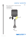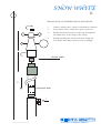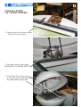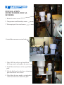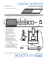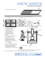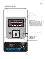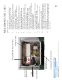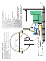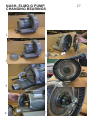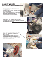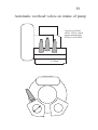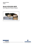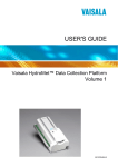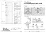
1
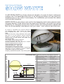
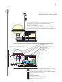
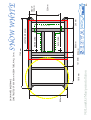
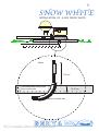
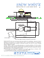
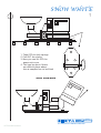
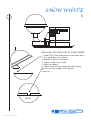
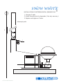
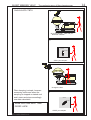
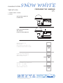
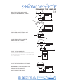
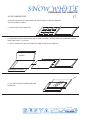
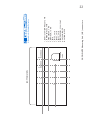
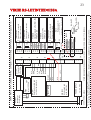
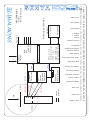
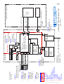
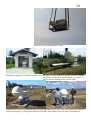
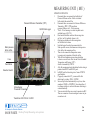
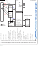
SENYA
FINLAND
High Volume Air Sampler
SNOW WHITE
SENYA
FINLAND
High Volume Air Sampler
SNOW WHITE
2
JL-900 SNOW WHITE is a high volume air sampler. It´s ment for hard, continuous
outdoor use. The baseframe structure is so strong that whole unit can easily be
installed even on four rocks if neccessary. For installation just connect the mains
cord and start sampling.
SNOW WHITE is very easy to use and in the designing work users opinions were
listened carefully. Pump control can be made with frequency converter thus giving
possibility for changing volume flow. Panel meters are microprocessor based and
they do all neccessary calculations that you need; total volume and total time.
Air volume is calculated from pressure difference
over calibrated orifice, also in carbon line. Carbon
line is equipped with valve, so it can be closed
totally.
Pressure drop when using Whatman GF/A glass
fiber filter is c.10.000 Pascals. Pumps maximum
efficiency is 20.000 Pascals so there is lots of
reserve power to hold volume flow stable even
when filter gets filled.
Filter cassette, which is made of aluminium,
can be loaded already in laboratory thus
avoiding problems with rain and wind outside.
Pipes and supporting frames are made of
stainless steel which is electrochemically
polished after fabrication. GRP, glass
reinforced plastic covers are thick enough
to withstand even small flying stones or hammering.
GM-probes can be installed to measure radiation
concentration on filter.They can be used for
emergency preparedness purposes; early warning system.
Technical data
1510 mm
950 mm
JL-900 SNOW WHITE
SENYA
~ 1900 mm
Gas ring vacuum pump NASH- ELMO-G
Power norm / max.
6kW / 9 kW
Vacuum max.
200 mbar
Volume flow, filter
300-900 m3/ h
carbon
0 - 14 m3/ h
Filter size, particle
570 x 460 mm
Filters: Whatman GF/A, Macherey-NagelCamfil A600G,
MN 85 / 90
Carbon
0.5 l
Covers
GRP, glass
reinforced plastics
Air Pipes, frames
Stainless steel
Aluminium parts
Anodized
PDTs
HUBA Control
VAISALA
Panelmeters
NOKEVAL
Datalogger
VAISALA
Weight
400 +/-10kg
3
SNOW WHITE. OUT and IN
JL-900 SNOW WHITE is a powerful aersol sampler.
It is ment for continuous hard outdoor use.
Air flow is 900m3/h.
Pump power is 9kW, 3-phase.
Covers are strong glass reinfoced plastics ( GRP )
Base frames and tubing are Stainless Steel ( AISI 304)
SNOW WHITE SENYA
1.
2.
3.
4.
5.
6.
7.
Place for possible GM-tubes
Intake Sphere
Filter
Flow measuring orifice
Pump Cover
Measuring Unit
Pump
Base Frame
STOP
START
fuse
1.5 m
2m
Covers are made of GRP, glass reinforced plastics
Particle filter is on EPDM-rubber gasket.
Activated carbon holder. Not in CTBTO sampler.
Pressure difference orifices.
Silencers.
Vibration dampers.
Tube gasket of neopren rubber.
Stainless steel base frame
1610mm
9G/Lumikki/Man/preinstallation
800mm
1210mm
SENYA
950mm
860mm
DATA CORD
MAINS CORD
LESS THAN 860mm
260mm
P
U
M
P
FINLAND
520mm
ABOUT
140mm
SNOW WHITE
1740mm
CONSTRUCTED OF 60 X 80mm AISI304 TUBE, WALL 3mm.
SNOW WHITE BASEFRAME
4
5
SNOW WHITE
INSTALLATION OF JL-900 SNOW WHITE
JL-900 SNOW WHITE SENYA
Mains
150 cm
Concrete platform with some
steel rods inside
10-15 cm
Plastic or metallic tube
SENYA
9G/Lumikki/Man/preinstallation
FINLAND
SNOW WHITE
INSTALLATION OF JL-900 SNOW WHITE
6
1m
JL-900 SNOW WHITE SENYA
150
MAINS CORD
95
50
250
50
350 cm
DATA CABLE
These pipes should be at least Ø 35 mm inside.
SNOW WHITE does not neccessary need any platform for installation. However if she is
installed on the ground it is a good thing to cast a concrete platform fro installation.
This platform should be wide enough so that station operator can work on it when changing
filters or doing service work.
JL-900 SNOW WHITE is normally placed on a concrete platform, 10-15 cm thick.
Normally customer leads electricity and data cables to sampler,under ground for safety reasons.
For that purpose there should be placed pipes, tubes for them before laying the concrete.
Cables should run c. 50 cm apart from each other.
Electricity cable: for pump UNIT, 3- phases, 1,2,3+0+PE, depending on distance, 9kW.
for measuring unit: 1-phase, 1+0+PE from stations UPS, 250W.
Data cable: We will provide when we know the needed length.
SENYA
9G/Lumikki/Man/preinstallation
FINLAND
SNOW WHITE
7
SENYA SNOW WHITE
1. Take OFF the lock springs
2. Pull OUT the shafts
3. Now you can lift OFF the
pump unit cover
4. This can be done if there
are difficult place where
the air sampler has to be lifted
SENYA SNOW WHITE
FINLAND
Air Samplers for Radiation Detection
9G/Lumikki/asennus
SNOW WHITE
8
SENYA SNOW WHITE
2
INSTALLING THE UPPER PART OF INTAKE SPHERE
1. Take OFF 4 nuts and spacers from lower part.
2. Lift upper part on its place
3. Replace 4 spacers and nuts
4. Tighten them only a little
5. Shut the sphere
6. Check from the front side that the locking
device is in the middle, if Ok tighten
the nuts.
FRONT
FINLAND
Air Samplers for Radiation Detection
9G/Lumikki/asennus
SNOW WHITE
INSTALLATION OF METEOROLOGICAL SENSOR POLE
9
1. Unscrew 2 bolts
2. Install the pole into the basetube ( fits only one way )
3. Replace and tightern 2 bolts.
telescopic pole
2
1
FINLAND
9G/Lumikki/asennus
Air Samplers for Radiation Detection
SNOW WHITE
10
INSTALLATION OF HUMIDITY & TEMPERATURE SENSOR
1. Unscrew plastic nut
2. Uninstall sensor.
3. Take off yellow cap.
3. Screw sensor in place
FINLAND
Air Samplers for Radiation Detection
9G/Lumikki/asennus
SNOW WHITE
11
INSTALLATION OF METEOROLOGICAL SENSOR POLE
1.
Connect wind sensor cable to windsensor element.
2.
Screw wind sensor element to pole connector.
3.
Install wind speed sensor to the top and tighten
the small nut; do not forget the O-ring.
4.
During installation check from data string the
true Notrh and align sensor pole accordingly.
Sensor cable
2
telescopic pole
1
FINLAND
9G/Lumikki/asennus
Air Samplers for Radiation Detection
FINLAND
Air Samplers for Radiation Detection
INSTALLATION
OF UPPER SPHERE
1. Open the nuts in the lower sphere.
- Lift up also the washers.
2. Lift upper sphere on its place.
BEWARE OF TAMPER SWITCH.
3. Check that the locking spring
is in right position and tighten
the upper sphere hinge nuts.
12
FINLAND
Air Samplers for Radiation Detection
INSTALLATION
OF METEOROLOGICAL
SENSORS
1. Rain fall sensor.
2. Temperature and Humidity sensor.
3. Telescopic pole for wind sensor.
1. Install the cross arm on two bolts.
1. Take OFF the yellow cap from Hum.
& Temp sensor and replace the sensor.
2. Install the wind sensor to the top of black
pole.
3. Lift the black pole to the lower aluminum
pole and secure two screws.
4. Check that the true notrh is at right place.
if not turn the lower aluminum pole.
13
SHORT MEMORY HELP
The continuing story of filter changing man
?
SNOW WHITE.CTBTO
1
SNOW WHITE
Go to the sampler. Take with you.
- New filter cassette
2
STOP
START
STOP your sampler.
3
JL-900 SNOW WHITE SENYA
Change the filter.
Filter changing is simple, because
measuring unit knows when the
sampling is stopped or started and
and it starts and stops accordingly
new data calculation.
4
STOP
START
SAME ROUTINE NEXT TIME.
GOOD LUCK.
START your sampler.
9G/Lumikki/MAN/serie
14
CHANGING FILTERS
TAKE WITH YOU:
SNOW WHITE
PREPARING THE SAMPLES
15
1. NEW FILTER + C0VER
3. KEYS
PUT FILTER CASSETTE
IN SHELTER
JL-900 SNOW WHITE SENYA
OPEN THE MEASURING
UNIT DOOR
STOP THE AIR SAMPLER
JL-900 SNOW WHITE SENYA
WRITE DOWN THE
PRESSURE
DIFFERENCE VALUES, CH A
IN MEASURING SHEET FROM
STOP THE AIR SAMPLER
AND WRITE THE TIME IN
MEASURING SHEET
WRITE DOWN THE VALUES IN
CH AB=......m 3AND
CH C=......hours / min
FROM PANEL METER
SENYA
9G/Lumikki/MAN/changes
FINLAND
SNOW WHITE
PREPARING THE SAMPLES
16
OPEN THE FILTER UNIT COVER.
HANDLE IS IN THE MIDDLE, UNDER
THE LID.
JL-900 SNOW WHITE SENYA
OPEN THE 8 CLAMPS, THAT HOLD
THE FILTER CASSETTE IN PLACE.
REMOVE THE OLD FILTER.
PLACE NEW FILTER CASSETTE
AND CLOSE THE CLAMPS.
CLOSE THE FILTER UNIT COVER.
JL-900 SNOW WHITE SENYA
START THE AIR SAMPLER
WRITE DOWN THE TIME IN MEASURING SHEET.
LET METERS SETTLE DOWN 1 MIN AND READ
CH A READINGS.
CLOSE THE MEASURING UNIT DOOR.
REMEMBER TO TAKE AWAY WITH YOU
THE OLD FILTER CASSETTE
AND MEASURING SHEET.
DON´T FORGET THE KEYES.
SENYA
9G/Lumikki/MAN/changes
JL-900 SNOW WHITE SENYA
FINLAND
SNOW WHITE
PREPARING THE SAMPLES
IN THE LABORATORY
17
ALWAYS CLEAN THE FILTER CASSETTE WITH ETANOL ALCOHOL BEFORE
YOU PUT NEW FILTER IN.
1. OPEN THE FILTER CASSETTE
2. TAKE ONE FILTER PAPER FROM THE FILTER PACKAGE. NEVER TAKE THE COVERING PAPER.
TAKE ONLY ONE ( 1 ) FILTER.
3. PUT IT CAREFULLY ON THE CASSETTE AND CLOSE THE CASSETTE.
COVER
WHATMAN FILTERS
4. PUT THE PLASTIC COVER OVER THE
CASSETTE.
SENYA
9G/Lumikki/MAN/changes
FINLAND
SNOW WHITE
PREPARING THE SAMPLES
PREPARING THE
18
1. OPEN THE FILTER CASSETTE
2. FOLD THE FILTER MANY TIMES AND FINALLY ROLL IT TO FIT IN THE PRESSING TOOL
FOLD
FOLD
ROLL
FOLD
3. PUT THE PRESSING TOOL
BOTTOM IN PLACE 1.
4. PUT THE FILTER ROLL IN
THE PRESSING TOOL
5. PUSH THE PISTON IN
THE PRESSING TOOL
6. PUT IT IN THE HYDRAULIC
PRESS.
7. OPEN THE SMALL BUTTON
ONE TURN ( AIR INTAKE )
8. CLOSE THE VALVE
9. PRESS WITH THE HANDLE
SO MANY TIMES THAT THE
METER SHOW C. 6 TONS.
10. OPEN THE VALVE, BY TURNING
TO LEFT
11. TAKE OFF THE PRESSING TOOL
12. TAKE OFF THE BOTTOM AND
USE THE PISTON TO PUSH
THE TABLETT OUT INTO THE
WILLIAMS P-35 PLASTIC HOLDER.
6 TONS
3.
2.
4.
1.
9.
7. OPEN 1 TURN
ALWAYS REMEMBER TO MARK THE SAMPLE ID INFORMATION.
SENYA
9G/Lumikki/MAN/changes
8.CLOSE THE VALVE
FINLAND
SNOW WHITE
PREPARING THE SAMPLES
19
1. OPEN THE FILTER CASSETTE
2. FOLD THE FILTER MANY TIMES AND FINALLY FIT IT IN THE PRESSING TOOL
FOLD
FOLD
FOLD
dia 70mm
WE HAVE WRAPPED THE FOLDED FILTER INTO CELLULOSE "TOWEL"
BEFORE PRESSING, THEN YOU GET A BETTER TABLET.
3. PUT THE PRESSING TOOL
BOTTOM IN PLACE 1.
4. PUT THE FILTER ROLL IN
THE PRESSING TOOL
5. PUSH THE PISTON IN
THE PRESSING TOOL
6. PUT IT IN THE HYDRAULIC
PRESS.
7. OPEN THE SMALL BUTTON
ONE TURN ( AIR INTAKE )
8. CLOSE THE VALVE
9. PRESS WITH THE HANDLE
SO MANY TIMES THAT THE
METER SHOW C. 15 TONS.
10. OPEN THE VALVE, BY TURNING
TO LEFT
11. TAKE OFF THE PRESSING TOOL
12. TAKE OFF THE BOTTOM AND
USE THE PISTON TO PUSH
THE TABLETT OUT INTO THE
WILLIAMS P-70? PLASTIC HOLDER.
15 TONS
8.CLOSE THE VALVE
3.
2.
4.
1.
9.
7. OPEN 1 TURN
ALWAYS REMEMBER TO MARK THE SAMPLE ID INFORMATION.
ALWAYS REMEMBER TO USE SAFETY GLASSES WHEN USING HYDRAULIC PRESS.
SENYA
9G/Lumikki/MAN/changes
FINLAND
20
CONTROL PANEL
PANEL METER
SHOWS
FILTERLINE
VALUES.
Panel meter calculates and stores
calculated total volume and time.
These values stay in memory
till the start / stop switch is
turned next time.
During the power outage the
panel meter goes to pause and
continues measuring from the values
it had before the power outage.
Volume is uncorrected value.
A1 A2 A3 A4
185000
MAIN ORIFICE
STOP
START
SOFT STARTER FAULT INDICATOR
When green, everything is OK.
START/STOP SWITCH
START AND STOP
YOUR SAMPLING
MEASURING UNIT FUSE
A1
A2
A3
A4
Pascal
m3/h
m3
hh:mm:ss
Scroll
with
FINLAND
Air Samplers for Radiation Detection
FINLAND
Transformer 230 V/50 Hz / 24 VDC
Mains Supply
Pneumatic Connectors
SNOW WHITE
Connectors
Desktop/Tietoja/Measuring unit operation
Air Samplers for Radiation Detection
Selection Switch
Panel Meter
Fuse
Static pressure
before orifice
QLC50 Data Logger
Pressure Difference Transmitter ( PDT )
OPERATION PRINCIPLE
1.
Pneumatic tubes are connected on both sides of
Pressure difference orifice. Orifice is situated
In the intake tube under filter.
2.
Penumatic tubes are connected to Pressure Difference
Transmitter ( PDT ). PDT transforms
pressure difference to 4 - 20 mA message.
3.
This 4 - 20 mA message is routed via panel meter
and data logger ( QLC50 ).
4.
Panel meter calculates and store this message into
air flow ( m3/h ) and total volume ( m3 ).
5.
Data logger calculates also this message into
air flow and total volume.
6.
Into data logger there has been connected also
Static pressure sensor, which measures static pressure
of air before the measuring orifice.
7.
There is also connected a temperature sensor
to measure air temperature, before the orifice.
8.
With all this information a correction calculation
is done to convert the air flow into air flow in Standard
Temperature and Pressure ( STP )
which is demanded by CTBTO.
9
After all measurements and calculation the data string is
produced into RS232 and RS 485 ports.
10.
In RS485 port the data string is in a form of CTBTO
specifications.
11.
If properly connected to PC, you can ask for this
data string by writing <POLL> ENTER
12.
Same out put is done automatically every time, when
sampler is START or STOPPED. Also when either of
two tamper swithces is activated the same data string is
sent automatically.
13.
You can notice that there are several connectors in MU.
There are connectors for meteorological sensors as you
can notice in att.
MEASURING UNIT ( MU )
21
2
4
5
1
3
6
8
7
9
BOTTOM VIEW
A
RED HOSE
1. START/STOP+LAMP+RESET, 5 PIN
2. TAMPER SWITCES, 4 PIN
3. WIND SENSOR, 5 PIN
4. TEMP+HUM, 10 PIN
5. RAIN,
6. PT100, 4 PIN
7. RS485, 5 PIN
8. RS232, 5 PIN
9. POWER SUPPLY, 230V/50HZ
A. VACUUM, LOWER
B. VACUUM, HIGER
SNOW WHITE Measuring Unit ( MU ) connectors
Condens
valve
B
BLUE HOSE
Air Samplers for Radiation Detection
FINLAND
22
sign.
output 4-20mA +
PDT 1
HUBA
5
3
+
-
gry
blk
(57)
1
2
3
4
5
6
7
8
9
10
11
12
13
14
15
16
17
18
19
20
21
22
23
24
25
26
27
28
29
30
31
32
33
34
14 15
12 13
10 11
9
7
6
8
5
3
1
4
2
0
35
TAMPER SW1
36
Switch open, status=0
1k
37
Filter cover closed
38
39
START/STOP
40
Switch open=measures
1k
41
/status=1
42
43 supply
PTB100B
44 vout
Static pressure after filter, kPa
45 agnd
VAISALA Ltd
46 gnd
47 supply
PTB100B
48 vout
agnd
Barometer, hPa
49
gnd
VAISALA Ltd
50
51
TAMPER SW2
52
Switch open, status=0
1k
53
Pump cover closed
54
55
55
RG13
56
47k
Rain gauge, mm
57
23
Jos ei ole anturia,
58 gr/ye (gr)
kytketään + 30 ( dig.gnd)
59
60 brown RXD
RS232
61 blue TXD
black
GND
62
63 + black SRD+
female D-9
64 - blue SRD65
RS485
pin5=SRD+
66
pin2=SRD67
68
CTBTO/SW/SENYA/25.06.2000/JL /02.07.00JL/29.08.00JL/17.10.2000JL
5
4
1 brown
2 wht
3 blu
VIO+RED
YEL
WHT
GRN
BLK
BLU
BRN
PT100
Temperature
after filter
NOTICES: 1. In Vienna, panelmeter is 24VDC.
2. For polling the data (RS485) you need RS-232 / RS-485 converter ( ADAM-4520); set baud rate to 9600.
230V/50Hz, 1-phase
12 - 30 VDC
POWER SUPPLY
WMS302
Wind speed and
wind direction
R3=47 kohm
QMH101
Relative humidity and
outside temperature
24 VDC
NOKEVAL
panelmeter
-local display
SNOW WHITE DATA LOGGER WIRING. Configuration according SNOWW.qsp in folder QLCCTBTO.
23
VIRHE RS-LIITINTIEDOISSA
start date
4-20mA
0-5V
RS485 CTBTO data
communication output
RS232 service &
configuration output.
VELHO output
QLC50 DATA LOGGER
relative humidity
start of data
POLL<ENTER>
QTerminal/cli
Computer
PortSettings=9600,N,8,1
- Sensors
- Data communication
MEASURING UNIT
FINLAND
24
9G/Lumikki/Man/diagram
(11.527*F3^0.4901)*SQRT((101.325/A3*(273.15+B3)/293.15))*A3*2.69578/(273.15+B3) = dm3/s ( STP )
S 2000/07/22 18:49:01 01:53:00 1 784 539.8 1048.2 22.3 103.2 23.0 36 0.5 1031.6 58.7 0.0 0 0 2000/07/22 20:42:05 E
sampling duration
NOKEVAL
Back up Display
sampler status
electric
pneumatic
pressure difference
F3 ( Pa )
start time
PDT
Pressure
Differerence
Transmitter
average flow rate
Orifice
temp after filter
PTB100B
Static pressure
static press after filter
A3 ( kPa )
sampled air volume
Wind
Rain
Temp & Hum
Barometric
outside temp
PT100
average wind dir
B3 ( °C )
rainfall
tamper 1
tamper 2
Filter
average wind speed
Stop/Start
update time
Tamper 1
Tamper 2
end of data
AIR
Barometric
SNOW WHITE
update date
SENYA
9
PUMP
MOTOR
1
OPERATION
SWITCH
STOP/START
MAIN
3 X 400 V SWITCH
LOCAL DISPLAY
QLC50
- reads sensors
- calculates air flow in STP
- sends data to PC, via RS485
1/10s
FREQUENCY
INVERTER
10
5
4
3
6
7
8
MEASURING UNIT
2
7
8
RNXXX OFFICE / LABORATORY
9
Stations UPS
9G/Lumikki/Man/diagram
JL/28.07.2000
SNOW WHITE.CTBTO GENERAL LAYOUT
Air Samplers for Radiation Detection
FINLAND
9. POWER SUPPLY, for Measuring Unit
230 V/50Hz
7. RS485 OUT ( 5-NAP )
PortSettings=9600,N,8,1
PC
- displays
- updates
- stores
8. RS232 IN/OUT ( 5-NAP)
2. SENSORS 11+12
TAMPER INDICATION 1+2
( 5-nap-liitin )
SENSORS INSIDE:
SENSOR 8
Pressure difference
over orifice
SENSOR 7
Static pressure
before the orifice
SENSOR 5
Barometric pressure
5
POWER SUPPLY
3 X 400 V/50 HZ ( 25 A FUSES IN SUPPLY BOARD )
3-PHASES + 0 + PE
1. SENSORS 10
START/STOP
FAULT INDICATOR
( 5-NAP-LIITIN )
3. 1+2 WMS302
4. 3+4 QMH101
5 PTB100B
5. 6 RG13
7 PTB100B
8 HUBA (0-3000)
6. 9 PT100 (NOKEVAL)
1. 10 SWITCH+LAMP+RESET
2. 11 SWITCH
2. 12 SWITCH
7. RS485
8 RS232
9. 230V/50Hz
CONNECTORS
SENSORS X
5. SENSOR 6
PERCIPITATION
( 5-nap-liitin )
4. SENSORS 3+4
TEMPERATURE
REL. HUMIDITY
( 10-nap-liitin )
OPTIONAL SENSORS
1
3. SENSORS 1+2
WIND DIRECTION 2
3
WIND SPEED
4
( 5-nap-liitin )
6
6. SENSOR 9
Temperature before orifice
( piuhaliitin tarvitaan myös )
Pneumatic tubes
from orifice
AIR SAMPLER
25
Clean and lubricate clamps.
SNOW WHITE pump is similar to HUNTER pump. Please look at the enclosed
pictures of changing the ball bearings to HUNTER.
In SNOW WHITE you don´t have to remove the pump from sampler. You can
do the service in place.
Motor end ball bearing is very tight and you should warm it before removing
and installing.
Always put grease to new ball bearings.
INSIDE VIEW of SNOW WHITE.
1
2
3
4
5...
11
12
13....
1. Loosen screws and remove cooling air intake tube.
2. Loosen screws and remove motor fan cover.
3. Pull out plastic fan
4. Open screws and remove motor end plate.
5. Warm up the ball bearing.
6. Remove ball bearing.
7. Warm new ball bearing and install it.
8. Install motor end plate.
9. Install motor plastic fan.
10. Install fan cover.
11. Loosen 4 screws in the middle of the turbine.
12 Loosen bolts of turbine.
13. Gently remove turbine cover.
14. Remove ball bearing.
15. Install new ball bearing
16. Gently install turbine cover. With thin metal stick placed in
the middle holes adjust the the holding ring in place when
installing turbine cover.
17. Check from cooling fan that the turbine is rolling easily, if not
hit with plastic hammer to turbine end cover and check again.
26
NASH- ELMO-G PUMP
CHANGING BEARINGS
1
5
2
3
4
6
7
27
SNOW WHITE
CHANGING BALL BEARINGS
PUMP IN SNOW WHITE IS SIMILAR TO
HUNTER PUMP.
DISMANTLING IS DONE THE SAME WAY
AS WITH HUNTER.
HERE YOU CAN SEE HOW TO REPLACE
NEW BALL BEARING IN SAFT.
DO THIS CHANGE ALWAYS FIRST, BECAUSE
YOU HAVE TO HIT IT QUITE HARD.
THEN OPEN THE TURBINE END OF PUMP.
LOOSEN FIRST FOUR CROSS HEADED SCREWS
IN THE MIDDLE OF PUMP.
THEN OPEN BOLTS.
TAKE OFF THE BEARING AND HOLDER.
TAKE OFF BEARING FROM HOLDER.
WIPE CLEAN.
GREASE NEW BEARING AND PLACE.
ASSEMBLE PUMP AND CHECK THAT IT
REVOLVES FREELY, IF NOT HIT WITH
RUBBER OR PLASTIC HAMMER ON THE
TURBINE CENTER COVER.
28
29
Automatic overload valves on intake of pump
3 pieces overload
valves. These valves
open automatically
if filter is too filled
n. 50cm
30
Easiest way to lift sampler on site
Somrtimes sampler is installed inside a hut. Sampler is delivered with plastic flexible exhaust
tube,but it is always a good practice to replace it
locally with a stainless steel Ø205 tube.
Installed on concrete platform large enough quarantees you that you do not have to work on
mud in rainy days. On right the motor cover has been lifted away for easy installations.
MEASURING UNIT ( MU )
Pressure Difference Transmitter ( PDT )
QLC50 Data Logger
Static pressure
before orifice
Fuse
Panel Meter
Selection Switch
Mains Supply
Pneumatic Connectors
Connectors
Transformer 230 V/50 Hz / 24 VDC
Air Samplers for Radiation Detection
SNOW WHITE
Desktop/Tietoja/Measuring unit operation
21
FINLAND
OPERATION PRINCIPLE
1.
Pneumatic tubes are connected on both sides of
Pressure difference orifice. Orifice is situated
In the intake tube under filter.
2.
Penumatic tubes are connected to Pressure Difference
Transmitter ( PDT ). PDT transforms
pressure difference to 4 - 20 mA message.
3.
This 4 - 20 mA message is routed via panel meter
and data logger ( QLC50 ).
4.
Panel meter calculates and store this message into
air flow ( m3/h ) and total volume ( m3 ).
5.
Data logger calculates also this message into
air flow and total volume.
6.
Into data logger there has been connected also
Static pressure sensor, which measures static pressure
of air before the measuring orifice.
7.
There is also connected a temperature sensor
to measure air temperature, before the orifice.
8.
With all this information a correction calculation
is done to convert the air flow into air flow in Standard
Temperature and Pressure ( STP )
which is demanded by CTBTO.
9
After all measurements and calculation the data string is
produced into RS232 and RS 485 ports.
10.
In RS485 port the data string is in a form of CTBTO
specifications.
11.
If properly connected to PC, you can ask for this
data string by writing <POLL> ENTER
12.
Same out put is done automatically every time, when
sampler is START or STOPPED. Also when either of
two tamper swithces is activated the same data string is
sent automatically.
13.
You can notice that there are several connectors in MU.
There are connectors for meteorological sensors as you
can notice in att.
FINLAND
BOTTOM VIEW
1
2
9
3
4
7
6
5
8
Air Samplers for Radiation Detection
A
RED HOSE
B
BLUE HOSE
Condens
valve
1. START/STOP+LAMP+RESET, 5 PIN
2. TAMPER SWITCES, 4 PIN
3. WIND SENSOR, 5 PIN
4. TEMP+HUM, 10 PIN
5. RAIN,
6. PT100, 4 PIN
7. RS485, 5 PIN
8. RS232, 5 PIN
9. POWER SUPPLY, 230V/50HZ
A. VACUUM, LOWER
B. VACUUM, HIGER
22
SNOW WHITE Measuring Unit ( MU ) connectors
SNOW WHITE DATA LOGGER WIRING. Configuration according SNOWW.qsp in folder QLCCTBTO.
NOKEVAL
panelmeter
-local display
3
PT100
Temperature
after filter
5
24 VDC
PDT 1
HUBA
sign.
output 4-20mA +
BLU
BRN
QMH101
Relative humidity and
outside temperature
R3=47 kohm
1 brown
2 wht
3 blu
4
WMS302
Wind speed and
wind direction
5
POWER SUPPLY
230V/50Hz, 1-phase
+
-
blk
gry
(57)
0
1
2
3
4
5
6
7
8
9
10 11
12 13
14 15
35
TAMPER SW1
36
Switch open, status=0
1k
37
Filter cover closed
38
39
START/STOP
40
Switch open=measures
1k
41
/status=1
42
43 supply
PTB100B
44 vout
Static pressure after filter, kPa
45 agnd
VAISALA Ltd
46 gnd
47 supply
PTB100B
48 vout
agnd
Barometer, hPa
49
gnd
VAISALA Ltd
50
51
TAMPER SW2
52
Switch open, status=0
1k
53
Pump cover closed
54
55
55
RG13
56
47k
Rain gauge, mm
57
23
Jos ei ole anturia,
58 gr/ye (gr)
kytketään + 30 ( dig.gnd)
59
60 brown RXD
RS232
61 blue TXD
black
GND
62
63 + black SRD+
female D-9
64 - blue SRD65
RS485
pin5=SRD+
66
pin2=SRD67
68
CTBTO/SW/SENYA/25.06.2000/JL /02.07.00JL/29.08.00JL/17.10.2000JL
NOTICES: 1. In Vienna, panelmeter is 24VDC.
2. For polling the data (RS485) you need RS-232 / RS-485 converter ( ADAM-4520); set baud rate to 9600.
23
12 - 30 VDC
VIO+RED
YEL
WHT
GRN
BLK
1
2
3
4
5
6
7
8
9
10
11
12
13
14
15
16
17
18
19
20
21
22
23
24
25
26
27
28
29
30
31
32
33
34
Filter
Tamper 2
PT100
A3 ( kPa )
PTB100B
Static pressure
0-5V
QLC50 DATA LOGGER
PDT
Pressure
Differerence
Transmitter
PortSettings=9600,N,8,1
end of data
update time
update date
POLL<ENTER>
relative humidity
Barometric
average wind speed
average wind dir
outside temp
temp after filter
sampled air volume
average flow rate
pressure difference
sampler status
start time
start date
RS485 CTBTO data
communication output
24
start of data
QTerminal/cli
FINLAND
sampling duration
NOKEVAL
Back up Display
electric
pneumatic
Computer
RS232 service &
configuration output.
VELHO output
rainfall
tamper 1
tamper 2
4-20mA
static press after filter
F3 ( Pa )
Wind
Rain
Temp & Hum
Barometric
SENYA
B3 ( °C )
- Data communication
S 2000/07/22 18:49:01 01:53:00 1 784 539.8 1048.2 22.3 103.2 23.0 36 0.5 1031.6 58.7 0.0 0 0 2000/07/22 20:42:05 E
(11.527*F3^0.4901)*SQRT((101.325/A3*(273.15+B3)/293.15))*A3*2.69578/(273.15+B3) = dm3/s ( STP )
an/diagram