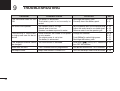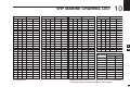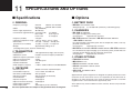
1
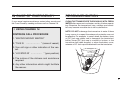
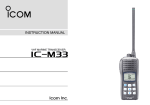
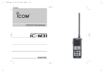
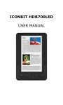
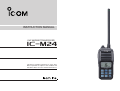
INSTRUCTION MANUAL
VHF MARINE TRANSCEIVER
iM24
This device complies with Part 15 of the FCC
Rules. Operation is subject to the condition that
this device does not cause harmful interference.
FOREWORD
FEATURES
Thank you for purchasing this Icom radio. The IC-M24 VHF
MARINE TRANSCEIVER is designed and built with Icom’s state of
the art technology and craftsmanship. With proper care this
radio should provide you with years of trouble-free operation.
☞ Floats on water
• When a third-party battery pack, strap, antenna, etc. is used, it may sink.
IMPORTANT
READ ALL INSTRUCTIONS
carefully and com-
pletely before using the transceiver.
SAVE THIS INSTRUCTION MANUAL—This
instruction manual contains important operating instructions
for the IC-M24.
EXPLICIT DEFINITIONS
WORD
RDANGER!
DEFINITION
Personal death, serious injury or an explosion may occur.
Personal injury, fire hazard or electric
RWARNING!
shock may occur.
CAUTION
NOTE
i
The transceiver floats in fresh or salt
water even when the supplied accessories are attached.
Equipment damage may occur.
If disregarded, only inconvenience. No risk
of personal injury, fire or electric shock.
☞ Floats and flashes
An LED sends out intermittent light from
a transparent section on the bottom of
the radio, while floating in the water.
As the LED light stands out in the dark
(like a flashing fishing float), the radio
can be easily retrieved from the water.
This function works even when the
radio is turned OFF.
For Canada:
This device complies with RSS-310 of Industry Canada. Operation is subject
to the condition that this device does not cause harmful interference.
Cet appareil est conforme au CNR-310 d’Industrie Canada. Son exploitation
est autorisée sous réserve que l’appareil ne cause pas de brouillage
préjudiciable.
IN CASE OF EMERGENCY
RECOMMENDATION
If your vessel requires assistance, contact other vessels and
the Coast Guard by sending a distress call on Channel 16.
CLEAN THE TRANSCEIVER THOROUGHLY WITH FRESH
WATER after exposure to saltwater, and dry it before operating. Otherwise, the transceiver's keys, switches and controllers may become unusable due to salt crystallization.
❍ USING CHANNEL 16
DISTRESS CALL PROCEDURE
1. “MAYDAY MAYDAY MAYDAY.”
2. “THIS IS
……………… ” (name of vessel)
NOTE: DO NOT submerge the transceiver in water if there
is any reason to suspect the waterproof protection may not
be effective. For example, in cases where the battery cover
or [DC] jack cap rubber seal is damaged, the transceiver/
battery cover/[DC] jack cap is cracked or broken, or the
transceiver has been dropped, or when the battery cover,
antenna or DC Jack cap are detached from the transceiver.
3. Your call sign or other indication of the vessel.
4. “LOCATED AT …………… ” (your position)
5. The nature of the distress and assistance
required.
6. Any other information which might facilitate
the rescue.
ii
SAFETY TRAINING INFORMATION
Your Icom radio generates RF electromagnetic energy during
transmit mode. This radio is designed for and classified as
“General Population Use” in an uncontrolled environment.
This radio has been evaluated for compliance at the distance
of 2.5 cm (1 inch) with the FCC RF exposure limits for “General Population Use.” In addition, your Icom radio complies
with the following Standards and Guidelines with regard to RF
energy and electromagnetic energy levels and evaluation of
such levels for exposure to humans:
• FCC OET Bulletin 65 Edition 01-01 Supplement C, Evaluating Compliance with FCC Guidelines for Human Exposure to Radio Frequency
Electromagnetic Fields.
• American National Standards Institute (C95.1-1992), IEEE Standard
for Safety Levels with Respect to Human Exposure to Radio Frequency
Electromagnetic Fields, 3 kHz to 300 GHz.
• American National Standards Institute (C95.3-1992), IEEE Recommended Practice for the Measurement of Potentially Hazardous Electromagnetic Fields– RF and Microwave.
• The following accessories are authorized for use with this product. Use of
accessories other than those specified may result in RF exposure levels
exceeding the FCC requirements for wireless RF exposure.; Belt Clip
(MB-124), Rechargeable Li-Ion Battery Pack (BP-266).
To ensure that your expose to RF electromagnetic energy is within the FCC allowable limits for general population use, always adhere to the following guidelines:
iii
• DO NOT operate the radio without a proper antenna attached, as this
may damaged the radio and may also cause you to exceed FCC RF exposure limits. A proper antenna is the antenna supplied with this radio by
the manufacturer or antenna specifically authorized by the manufacturer
for use with this radio.
• DO NOT transmit for more than 50% of total radio use time (“50% duty
cycle”). Transmitting more than 50% of the time can cause FCC RF exposure compliance requirements to be exceeded. The radio is transmitting
when the “transmit indicator” appears on the LCD. You can cause the
radio to transmit by pressing the “PTT” switch.
• ALWAYS keep the antenna at least 2.5 cm (1 inch) away from the body
when transmitting and only use the Icom belt clip which is listed on p. 28
when attaching the radio to your belt, etc., to ensure FCC RF exposure
compliance requirements are not exceeded. To provide the recipients of
your transmission the best sound quality, hold the antenna at least 5 cm
(2 inches) from your mouth, and slightly off to one side.
The information listed above provides the user with the information needed
to make him or her aware of RF exposure, and what to do to assure that this
radio operates with the FCC RF exposure limits of this radio.
Electromagnetic Interference/Compatibility
During transmissions, your Icom radio generates RF energy that can possibly
cause interference with other devices or systems. To avoid such interference,
turn off the radio in areas where signs are posted to do so. DO NOT operate
the transmitter in areas that are sensitive to electromagnetic radiation such as
hospitals, aircraft, and blasting sites.
INFORMATION EN MATIÈRE DE SÉCURITÉ
Votre radio Icom produit une énergie électromagnétique
de radiofréquences (RF), en mode de transmission. Elle
est conçue pour une «utilisation grand public», dans un
environnement non contrôlé. Cet appareil a été évalué
et jugé conforme, à 2,5 cm, aux limites d'exposition aux
A V E R T I S S E M E N T RF de la FCC, pour une «utilisation grand public». En
outre, votre radio Icom satisfait les normes et directives
qui suivent en matière de niveaux d'énergie et d'énergie
électromagnétique de RF et d'évaluation de tels niveaux en
ce qui concerne l'exposition humaine :
• Supplément C, édition 01-01, du Bulletin OET de la FCC, «Evaluating
Compliance with FCC Guidelines for Human Exposure to Radio Frequency
Electromagnetic Fields».
• Norme de l’American National Standards Institute (ANSI) : IEEE C95.11992 sur les niveaux de sécurité compatibles avec l’exposition humaine aux
champs électromagnétiques de radiofréquences (3 kHz à 300 GHz).
• Nor me de l’ANSI : IEEE C95.3-1992 sur la méthode d’évaluation
recommandée du champ magnétique potentiellement dangereux des
radiofréquences et des micro-ondes.
• Les accessoires qui suivent sont approuvés pour une utilisation avec ce
produit. L'utilisation d'accessoires autres que ceux précisés peut entraîner
des niveaux d'exposition aux RF supérieures aux limites établies par la FCC
en matière d'exposition aux RF sans fil; attache pour ceinture (MB-124),
bloc-piles rechargeable au lithium-ion (BP-266).
CAUTION
Afin de vous assurer que votre exposition à une
énergie électromagnétique de RF se situe dans les
limites permises par la FCC pour une utilisation grand
MISE EN GARDE public, veuillez en tout temps respecter les directives
suivantes :
• NE PAS faire fonctionner la radio sans qu'une antenne appropriée y soit
fixée, car ceci risque d'endommager la radio et causer une exposition
supérieure aux limites établies par la FCC. L'antenne appropriée est celle
qui est fournie avec cette radio par le fabricant ou une antenne spécialement
autorisée par le fabricant pour être utilisée avec cette radio.
• NE PAS émettre pendant plus de 50% du temps total d'utilisation de
l'appareil («50% du facteur d'utilisation»). Émettre pendant plus de 50% du
temps total d'utilisation peut causer une exposition aux RF supérieure aux
limites établies par la FCC. La radio est en train d’émettre lorsque le témoin
du mode de transmission s'affiche sur l'écran ACL. La radio émettra si vous
appuyez sur le bouton du microphone.
• TOUJOURS tenir l'antenne éloignée d'au moins 2,5 cm de votre corps
au moment d'émettre et utiliser uniquement l'attache pour ceinture Icom
illustrée à la p. 28, lorsque vous attachez la radio à votre ceinture, ou à autre
chose, de façon à vous assurer de ne pas provoquer une exposition aux RF
supérieure aux limites fixées par la FCC. Pour offrir à vos interlocuteurs la
meilleure qualité de transmission possible, tenez l'antenne à au moins 5 cm
de votre bouche et légèrement de côté.
Les renseignements ci-dessus fournissent à l'utilisateur toute l'information
nécessaire sur l'exposition aux RF et sur ce qu'il faut faire pour assurer que
cette radio fonctionne en respectant les limites d'exposition aux RF établies
par la FCC.
Interférence électromagnétique et compatibilité
En mode de transmission, votre radio Icom produit de l'énergie de RF qui
peut provoquer des interférences avec d'autres appareils ou systèmes. Pour
éviter de telles interférences, mettez la radio hors tension dans les secteurs
où une signalisation l’exige. NE PAS faire fonctionner l'émetteur dans des
secteurs sensibles au rayonnement électromagnétique tels que les hôpitaux,
les aéronefs et les sites de dynamitage.
iv
PRECAUTIONS
RWARNING! NEVER
BE CAREFUL! The transceiver meets IPX7* require-
RWARNING! NEVER
ments for waterproof protection. However, once the transceiver has been dropped, waterproof protection cannot be
guaranteed because of possible damage to the transceiver's
case or the waterproof seal.
connect the transceiver to an
AC outlet. This may pose a fire hazard or result in an electric
shock.
hold the transceiver so that
the antenna is closer than 2.5 cm (1 inch) from exposed
parts of the body, especially the face or eyes, while transmitting. The transceiver will perform best if the microphone is
5 to 10 cm (2 to 4 inches) away from the lips and the transceiver is vertical.
CAUTION: NEVER connect the transceiver to a
power source other than the BC-199 or BP-266. Such a connection will ruin the transceiver.
* Only when the flexible antenna, battery cover and [DC] jack cap
are securely attached.
MAKE SURE the flexible antenna and battery cover are
securely attached to the transceiver, and that the antenna
and battery cover are dry before attachment. Exposing the
inside of the transceiver to water will result in serious damage to the transceiver.
DO NOT
use or place the transceiver in direct sunlight
or in areas with temperatures below –20°C (–4°F) or above
+60°C (+140°F).
KEEP the transceiver out of the reach of children.
KEEP the transceiver at least 0.9 meters (3.0 ft) away
from your vessel’s magnetic navigation compass.
Icom, Icom Inc. and the Icom logo are registered trademarks of Icom Incorporated (Japan) in Japan, the United States, the United Kingdom, Germany,
France, Spain, Russia and/or other countries.
v
TABLE OF CONTENTS
FOREWORD ..................................................................................... i
IMPORTANT ...................................................................................... i
EXPLICIT DEFINITIONS ................................................................... i
FEATURES ........................................................................................ i
IN CASE OF EMERGENCY ............................................................. ii
RECOMMENDATION ....................................................................... ii
SAFETY TRAINING INFORMATION ............................................... iii
INFORMATION EN MATIÈRE DE SÉCURITÉ ................................ iv
PRECAUTIONS ................................................................................ v
TABLE OF CONTENTS ................................................................... vi
FCC INFORMATION ...................................................................... vii
■ Lock function..........................................................................13
■ Monitor function .....................................................................13
■ Automatic backlighting ...........................................................13
■ AquaQuake Water Draining function......................................13
5 SCAN OPERATION ............................................................14–15
■ Scan types .............................................................................14
■ Setting TAG channels ............................................................15
■ Starting a scan.......................................................................15
1 OPERATING RULES ..................................................................1
6 DUALWATCH/TRI-WATCH .......................................................16
■ Description .............................................................................16
■ Operation ...............................................................................16
2 SUPPLIED ACCESSORIES AND ATTACHMENTS ...............2–3
■ Supplied accessories ...............................................................2
■ Attachments .............................................................................2
7 SET MODE ..........................................................................17–20
■ Set mode programming .........................................................17
■ Set mode items ......................................................................18
3 PANEL DESCRIPTION ...........................................................4–7
■ Front, top and side panels .......................................................4
■ Function display .......................................................................6
8 BATTERY CHARGING .......................................................21–25
■ Battery caution.......................................................................21
■ Supplied battery charger .......................................................23
■ Optional battery charger ........................................................23
4 BASIC OPERATION .............................................................8–13
■ Channel selection ....................................................................8
■ Adjusting the volume level .....................................................10
■ Adjusting the squelch level ....................................................10
■ Receiving and transmitting ....................................................11
■ Call channel programming .....................................................12
■ Volume Loud function ............................................................12
■ Volume Mute function ............................................................12
9 TROUBLESHOOTING ..............................................................26
10 VHF MARINE CHANNEL LIST .................................................27
11 SPECIFICATIONS AND OPTIONS...........................................28
■ Specifications.........................................................................28
■ Options ..................................................................................28
vi
FCC INFORMATION
FOR CLASS B UNINTENTIONAL RADIATORS
This equipment has been tested and found to comply with
the limits for a Class B digital device, pursuant to part 15 of
the FCC Rules. These limits are designed to provide reasonable protection against harmful interference in a residential
installation. This equipment generates, uses and can radiate
radio frequency energy and, if not installed and used in accordance with the instructions, may cause harmful interference to radio communications. However, there is no guarantee that interference will not occur in a particular installation.
If this equipment does cause harmful interference to radio
or television reception, which can be determined by turning
the equipment off and on, the user is encouraged to try to
correct the interference by one or more of the following measures:
• Reorient or relocate the receiving antenna.
• Increase the separation between the equipment and receiver.
• Connect the equipment into an outlet on a circuit different
from that to which the receiver is connected.
• Consult the dealer or an experienced radio/TV technician
for help.
CAUTION:
Changes or modifications to this device, not
expressly approved by Icom Inc., could void your authority to
operate this device under FCC regulations.
vii
OPERATING RULES
D Priorities
• Read all rules and regulations pertaining to call priorities,
and keep an up-to-date copy handy. Safety and distress
calls take priority over all others.
• You must monitor Channel 16 when you are not operating
on another channel.
1
(2) OPERATOR’S LICENSE
A Restricted Radiotelephone Operator Permit is the license
most often held by small vessel radio operators when a radio
is not required for safety purposes.
If required, the Restricted Radiotelephone Operator Permit
must be posted or kept with the operator. If required, only a
licensed radio operator may operate a transceiver.
• False or fraudulent distress calls are prohibited under law.
D Privacy
• Information overheard, but not intended for you, cannot
lawfully be used in any way.
• Indecent or profane language is prohibited.
D Radio licenses
(1) SHIP STATION LICENSE
You may require a current radio station license before using
the transceiver. It is unlawful to operate a ship station which
is not licensed, but required to be.
If required, contact your dealer or the appropriate government agency for a Ship-Radiotelephone license application.
This government-issued license states the call sign which is
your craft’s identification for radio purposes.
However, non-licensed individuals may talk over a transceiver if a licensed operator starts, supervises, ends the call
and makes the necessary log entries.
A current copy of the applicable government rules and regulations is only required to be on hand for vessels in which a
radio telephone is compulsory. However, even if you are not
required to have these on hand it is your responsibility to be
thoroughly acquainted with all pertinent rules and regulations.
NOTE: Even though the IC-M24 is capable of operation
on VHF marine channels 3, 21, 23, 61, 64, 81, 82 and
83, according to FCC regulations these simplex channels
cannot be lawfully used by the general population in USA
waters.
1
2
3
4
5
6
7
8
9
10
11
12
13
14
15
16
1
2
SUPPLIED ACCESSORIES AND ATTACHMENTS
■ Supplied accessories
Handstrap
Battery pack
Charger
D Handstrap
Pass the handstrap through
the loop on the back side of
the transceiver as shown.
Belt clip
Flexible antenna
D Belt clip
Attach the belt clip to, or detach the belt clip from the transceiver.
To attach the belt clip
Belt clip
■ Attachments
D Flexible antenna
Connect the supplied flexible antenna to the antenna connector.
CAUTION:
• NEVER carry the transceiver by
holding just the antenna.
• Transmitting without an antenna
can damage the transceiver.
2
To detach the belt clip
Be careful!
Don’t break your
fingernail.
q
Lift the tab up (q), and slide
the belt clip in the direction
of the arrow (w).
w
SUPPLIED ACCESSORIES AND ATTACHMENTS
D Battery pack
To remove the battery pack:
Slide the latch and then lift the battery cover to remove it.
Then remove the battery pack, as shown.
Latch
Battery pack
Battery cover
To insert the battery pack:
Place the battery pack into the transceiver so it fits flat, and
then securely attach the battery cover, as shown.
NEVER remove the battery cover when the transceiver is
wet or soiled. This may result in water or dust getting into
the transceiver/battery pack, and may result in the transceiver being damaged.
CAUTION:
• When attaching or removing the battery cover, make sure
the rubber seal is correctly set in the groove of the cover.
If the seal is not correctly in the groove, it may be damaged when attaching the battery cover. If the seal is damaged, waterproof protection is not guaranteed.
• When attaching the battery cover, make sure dust or
other material does not adhere to the rubber seal. If dust
or other material is on the seal when attaching the battery
cover, waterproof protection may not be guaranteed.
Make sure the rubber seal is properly seated in the
groove and there is dust or other material is on it.
Push the cover until
the latch comes back
to the locked position.
“Click”
2
Incorrect position
Correct position
1
2
3
4
5
6
7
8
9
10
11
12
13
14
15
16
Rubber seal
Battery cover
Groove
Battery cover
Battery cover
3
3
PANEL DESCRIPTION
■ Front, top and side panels
q ANTENNA CONNECTOR (p. 2)
Connect the supplied antenna here.
q
w DC JACK [DC] (p. 23)
Connect the charger or optional cable here.
w
q To remove the [DC] jack cap, rotate it
counter clockwise.
e
Speaker
Microphone
Function
display
(pp. 6, 7)
w Pull the cap up to detach it.
u
i
r
t
y
4
o
!0
!1
NOTE: Attach the [DC] jack cap when the charger or optional cable is not connected. Otherwise, water will get into
the transceiver. When attaching the [DC] jack cap, make
sure dust or other material does not adhere to the rubber
seal. If dust or other material is on the seal when attaching
the cap, waterproof protection may not be guaranteed.
e PTT SWITCH [PTT]
Hold down to transmit; release to receive. (p. 11)
r CHANNEL 16 KEY [16 9]
➥ Push to select Channel 16. (p. 8)
➥ Hold down for 1 second to select the Call channel. (p. 8)
➥ When the Call channel is selected, hold down for 3 seconds
to enter the Call channel programming mode. (p. 12)
➥ While in the Set mode, push to return to the normal operating mode. (p. 17)
PANEL DESCRIPTION
t VOLUME/SQUELCH/MONITOR KEY [VOL/SQL MONI]
➥ Push to enter the volume adjustment mode or the
squelch adjustment mode. (p. 10)
Normal operating mode
PUSH
Volume adjustment mode
PUSH
Squelch adjustment mode
PUSH
➥ Hold down for 1 second to activate the Monitor function. (p. 13)
➥ While holding down this key, hold down [ ] to turn ON
the power and enter the Set mode. (p. 17)
➥ While in the Set mode, push to select an item. (p. 17)
➥ While holding down this key, push [Z] to turn ON the
Volume Mute function. Do the same steps again to turn
OFF the function. (p. 12)
➥ While holding down this key, push [Y] to turn ON the
Volume Loud function. Do the same steps again to turn
OFF the function. (p. 12)
y SCAN/DUAL KEY [SCAN DUAL]
➥ Push to start or stop a normal or priority scan. (p. 15)
➥ Hold down for 1 second to enter the Dual/Tri-watch
mode. (p. 16)
➥ Push to exit the watch mode. (p. 16)
➥ Hold down this key and [Hi/Lo] for 1 second, to activate
the AquaQuake function. (p. 13)
3
u UP/DOWN KEYS [Y] or [Z]
➥ Push to select an operating channel. (pp. 8, 9)
➥ While in the Set mode, push to select the setting or
value of an item. (p. 17)
➥ Push to check TAG channels or change scanning direction during a scan. (p. 15)
i FAVORITE/TAG KEY [FAV TAG]
➥ Push to sequentially select the favorite (TAG) channels, while ignoring untagged channels, in a channel
group. (p. 8)
➥ Hold down for 1 second to set or clear the TAG for the
displayed channel. (p. 15)
➥ While holding down, turn ON the power to clear or set
all TAG channels in the selected channel group. (p. 15)
o CHANNEL/WEATHER CHANNEL KEY [CH/WX U/I/C]
➥ Push to switch between a regular channel and a
weather channel. (p. 9)
➥ Hold down for 1 second to select the USA, International
and Canada channel groups. (p. 9)
➥ Push to return to the previous channel before selecting
Channel 16 or the Call channel. (p. 8)
!0 POWER KEY [ ]
Hold down to turn power ON or OFF.
!1 TRANSMIT POWER/LOCK KEY [Hi/Lo
]
➥ Push to select the high or low output power. (p. 11)
➥ Hold down for 1 second to turn the Lock function ON or
OFF. (p. 13)
1
2
3
4
5
6
7
8
9
10
11
12
13
14
15
16
5
3
PANEL DESCRIPTION
■ Function display
q
w
e
r
t
t CHARGE ICON (p. 23)
Appears while charging.
y
u
!7
!6
o
!5
i
!0
y BATTERY ICONS
➥ Displays the remaining battery capacity.
Indication
Charging
Exhausted
required
!1
Battery status
!2
!3
blinks when the battery is over charged.
➥ Scrolls while charging. (p. 23)
Full
Middle
!4
q TRANSMIT ICON (p. 11)
Appears while transmitting.
w BUSY ICON
➥ Appears while receiving a signal or when the squelch
opens. (p. 11)
➥ Blinks while monitoring. (p. 13)
e TAG CHANNEL ICON (p. 15)
Appears when a TAG channel is selected.
r CALL CHANNEL ICON (p. 8)
Appears when the Call channel is selected.
6
u SCAN ICON (p. 15)
Blinks during a scan.
i LOCK ICON (p. 13)
Appears when the Lock function is turned ON.
o DUALWATCH/TRI-WATCH ICONS (p. 16)
“DW” appears during Dualwatch; “TW” appears during Triwatch.
!0 DUPLEX ICON
Appears when a duplex channel is selected.
PANEL DESCRIPTION
!1 SUB CHANNEL READOUT
➥ Displays Channel 16 during a priority scan, Dualwatch
or Tri-watch. (p. 16)
➥ Displays the Set mode item while in the Set mode. (p. 17)
➥ Displays the volume level while in the volume adjustment mode. (p. 10)
➥ Displays the squelch level while in the squelch adjustment mode. (p. 10)
!2 SQUELCH LEVEL ICON
➥ Displays the squelch level.
➥ “SQL” blinks while adjusting the squelch level. (p. 10)
!3 VOLUME LEVEL ICON
➥ Displays the volume level.
➥ The bars repeatedly appear in ascending order when
the Volume Loud function is turned ON. (p. 12)
➥ The bars blink while the Volume Mute function is turned
ON. (p. 12)
➥ “VOL” blinks while adjusting the volume level. (p. 10)
!4 CHANNEL NUMBER READOUT
➥ Displays the selected operating channel number.
➥ In the Set mode, displays the selected setting or value.
(p. 17)
!5 CHANNEL GROUP ICON (p. 9)
“ ” appears when USA; “ ” appears when International;
“ ” appears when Canadian channel group is selected.
3
!6 WEATHER CHANNEL/WEATHER ALERT ICONS (p. 9)
➥ “WX” appears when the weather channel group is selected.
➥ “WX ALT” appears while the Weather Alert function is
turned ON; blinks when the alert tone is received.
!7 LOW POWER ICON (p. 11)
➥ “LOW” appears when low power is selected.
➥ “LOW” blinks when switching to the low power mode is
forced because of a high temperature error or low voltage.
1
2
3
4
5
6
7
8
9
10
11
12
13
14
15
16
7
4
BASIC OPERATION
■ Channel selection
IMPORTANT: Prior to using the transceiver for the first
time, the battery pack must be fully charged for optimum
life and operation (p. 23). To avoid damage to the transceiver, turn OFF the power while charging.
D Channel 16
Channel 16 is the distress and safety channel. It is used for
establishing initial contact with a station, and for emergency
communications. Channel 16 is monitored during both Dualwatch and Tri-watch. While in the standby mode, you must
monitor Channel 16.
q Push [16] momentarily to select Channel 16.
w Push [CH/WX] to return to the channel used before selecting Channel 16, or push [Y] or [Z] to select a different channel.
Push
Convenient!
While holding down [FAV], push [Y] or [Z] to select the favorite (TAG) channels.
• Pushing [FAV] only advances the displayed TAG channel.
• The favorite channels are selected using the TAG channel setting.
(p. 15)
8
D Channel 9 (Call channel)
Each regular channel group has a separate leisure-use Call
channel. The Call channel is monitored during Tri-watch. The
Call channels can be programmed, and are used to store
your most often used channel in each channel group, for
quick recall. (p. 12)
q Hold down [9] (16) for 1 second to select the Call channel
of the selected channel group.
• “CALL” and the Call channel number appear.
w Push [CH/WX] to return to the channel used before selecting the Call channel, or push [Y] or [Z] to select a
different channel.
Hold down
for 1 second
BASIC OPERATION
4
D USA, International and Canadian channels
D Weather channels
The transceiver is pre-programmed with 59 USA, 61 International and 65 Canadian channels. Choose the appropriate
channel groups for your operating area.
The transceiver has 10 weather channels. These are used
for monitoring broadcasts from NOAA (National Oceanic and
Atmospheric Administration).
q Push [CH/WX] to select a regular channel.
The transceiver can automatically detect a weather alert
tone on the selected weather channel while receiving another channel, or during a scan. (p. 18)
• If a weather channel appears, push [CH/WX] again.
w Hold down [U/I/C] (CH/WX) for 1 second to change the
channel group. Repeat to advance to the next group.
• USA, International and Canadian channel groups can be sequentially selected.
e Push [Y] or [Z] to select a channel.
• “DUP” appears for duplex channels.
• “A” appears when a simplex channel is selected.
q Push [CH/WX] once or twice to select the Weather channel group.
• “WX” appears when a weather channel is selected.
• “WX ALT” appears when the Weather Alert function is turned
ON. (p. 18)
w Push [Y] or [Z] to select a weather channel.
Push
once or twice.
U.S.A. channels
Hold down
for 1 second
Weather Alert is OFF.
International channels
Weather Alert is ON.
1
2
3
4
5
6
7
8
9
10
11
12
13
14
15
16
Canadian channels
9
4
BASIC OPERATION
■ Adjusting the volume level
■ Adjusting the squelch level
The volume level can be adjusted using [VOL/SQL] and [Y]
or [Z].
The squelch level can be adjusted using [VOL/SQL] and [Y]
or [Z].
In order to properly receive signals, as well as for the scan
to effectively function, the squelch must be adjusted to the
proper level.
q Push [VOL/SQL] once to enter the volume adjustment
mode, then push [Y] or [Z] to adjust the volume level.
• The “VOL” icon starts blinking.
• The transceiver has 31 volume levels and OFF.
• When no key operation is performed for 5 seconds, the transceiver returns to the normal mode.
w Push [VOL/SQL] twice to exit the volume adjustment
mode.
Displays the
volume level.
q Push [VOL/SQL] twice to enter the squelch adjustment
mode, then push [Y] or [Z] to adjust the squelch level.
• The “SQL” icon starts blinking.
• The transceiver has 11 squelch levels: OP is completely open;
10 is tight squelch; 1 is loose squelch.
• When no key operation is performed for 5 seconds, the transceiver returns to the normal mode.
w Push [VOL/SQL] again to exit the squelch adjustment
mode.
Blinks in the volume adjustment mode.
Displays the
squelch level.
Blinks in the squelch adjustment mode.
10
BASIC OPERATION
4
■ Receiving and transmitting
CAUTION: Transmitting without an antenna can damage
the transceiver.
q Hold down [
] to turn ON the power.
w Set the volume and squelch levels.
You can enter each adjustment mode by pushing [VOL/
SQL].
➥ Enter the squelch adjustment mode, and then push [Z] one or
more times to open the squelch.
➥ Enter the volume adjustment mode, and then push [Y] or [Z]
to adjust the volume level.
➥ Enter the squelch adjustment mode again, and push [Y] until
the noise just disappears.
e Push [VOL/SQL] again to exit the squelch adjustment mode.
r Push [Y] or [Z] to select a desired channel.
• When receiving a signal, “
” appears and audio is heard
from the speaker.
• You may want to further adjust the audio level.
t Push [Hi/Lo] to select the output power if necessary.
• “LOW” appears when low power is selected; no icon is
displayed when high power is selected.
• Choose low power for short range communications; choose
high power for longer distance communications.
• Some channels are for only low power communication.
y Hold down [PTT] to transmit, then speak into the microphone.
•“
” appears.
• Channel 70 cannot be used for transmission.
u Release [PTT] to receive.
IMPORTANT: To maximize the readability of your transmitted signal, pause for a second after pushing [PTT],
hold the microphone 5 to 10 cm (2 to 4 inches) from your
mouth and speak into the microphone at a normal voice
level.
NOTE: To conserve battery power, the transceiver’s
Power Save function automatically activates when no signal is received for 5 seconds.
For U.S.A version: To prevent prolonged transmission, a
time-out timer cuts OFF after 5 minutes of continuous
transmission.
y Push to
transmit.
u Release to
receive.
Microphone
w Adjust the
volume and
squelch level.
rSet channel.
w Enter the volume
and squelch adjustment mode.
q Power ON.
e Exit the squelch
adjustment mode.
t Set output
power.
1
2
3
4
5
6
7
8
9
10
11
12
13
14
15
16
11
4
BASIC OPERATION
■ Call channel programming
■ Volume Loud function
The Call channel is used to access Channel 9 (default).
However, you can program the Call channel with your most
often-used channel in each channel group, for quick recall.
The Volume Loud function temporarily maximizes the volume level.
This function has no effect when the volume level is 31.
q Hold down [U/I/C] (CH/WX) for 1 second, one or more
times, to select the desired channel group to be programmed (USA, International or Canada). (p. 9)
w Hold down [9] (16) for 1 second to select the Call channel
of the selected channel group.
q While holding down [VOL/SQL], push [Y] to turn ON the
Volume Loud function.
• “CALL” and the Call channel number appear.
e Hold down [9] (16) again for 3 seconds (until a long beep changes
to 2 short beeps) to enter the Call
channel programming mode.
• The channel number starts blinking.
r Push [Y] or [Z] to select the desired channel.
t Push [9] (16) to program the displayed channel as the Call channel.
• The channel number stops blinking.
• The volume level is set to the maximum level (level 31).
• The bars of the volume level icon repeatedly appear in ascending order.
w Push [VOL/SQL] and [Y] again to turn OFF the Volume
Loud function.
■ Volume Mute function
The Volume Mute function temporarily mutes the audio output.
This function has no effect when the volume level is OFF.
q While holding down [VOL/SQL], push [Z] to turn ON the
Volume Mute function.
• The volume level is set to the minimum level (OFF).
• The bars of the volume level icon blink.
w Push [VOL/SQL] and [Z] again to turn OFF the Volume
Mute function.
12
BASIC OPERATION
4
■ Lock function
■ Automatic backlighting
This function electronically locks all keys (except for [PTT], [VOL/
SQL], [MONI] (VOL/SQL), [
] (Hi/Lo) and [Y] or [Z]*) to prevent accidental changing of the channel and function access.
This function lights the function display and keys, and is convenient for night-time operation. The automatic backlighting
can be activated in the Set mode. (p. 20)
➥ Push any key except for [PTT] to turn ON the backlight.
* Only in the volume or squelch adjustment mode, and volume loud
and Volume Mute functions.
➥ Hold down [
] (Hi/Lo) for 1 second to turn the Lock
function ON and OFF.
Appears while the Lock function is activated.
Hold down
for 1 second
■ Monitor function
The Monitor function opens the squelch. The monitor key action can be selected in the Set mode. (p. 19)
➥ The Monitor function is activated by holding down [MONI]
(VOL/SQL).
•“
” blinks and the squelch opens.
Blinks while the monitor function is activated.
• The backlight is automatically turned OFF after 5 seconds of
inactivity.
■ AquaQuake Water Draining function
The AquaQuake Water Draining function removes water
from the speaker grill. Without this function, water may muffle
the sound coming from the speaker. The transceiver makes
a vibrating sound when this function is activated.
➥ Hold down both [SCAN] and [Hi/Lo].
• A low vibration tone sounds for 9 seconds to drain water, regardless of the volume level setting.
• The transceiver does not accept key operations while the
AquaQuake Water Draining function is activated.
1
2
3
4
5
6
7
8
9
10
11
12
13
14
15
16
Hold down
13
5
SCAN OPERATION
■ Scan types
Scanning is an efficient way to quickly locate signals over a
wide frequency range. The transceiver has a priority scan
and a normal scan.
Set the TAG channels (scanned channels) before scanning.
Clear the TAG for unwanted channels which inconveniently
stop scanning, such as those for digital communications. (p. 15)
In addition, the Weather Alert and Auto Scan functions are
selectable for standby convenience. These functions can be
simultaneously activated, depending on the setting in the
Set mode. (pp. 18, 19)
Choose the desired scan type from "Priority" or "Normal" in
the Set mode. (p. 18)
PRIORITY SCAN
NORMAL SCAN
CH 01
WX*
CH 02
CH 16
CH 05
CH 01
CH 03
CH 04
* Previously selected weather channel.
(when the Weather Alert function is activated)
A priority scan sequentially searches through all TAG
channels while monitoring Channel 16. When a signal is
detected on Channel 16, the scan pauses until the signal
disappears; when a signal is detected on a channel other
than Channel 16, the scan switches to Dualwatch, until
the signal disappears.
14
CH 02
WX*
CH 03
CH 05
CH 04
* Previously selected weather channel.
(when the Weather Alert function is activated)
A normal scan, like a priority scan, sequentially searches
through all TAG channels. However, unlike a priority scan,
Channel 16 is not checked unless Channel 16 is set as a
TAG channel.
SCAN OPERATION
5
■ Setting TAG channels
■ Starting a scan
For more efficient scanning, add the desired channels as
TAG channels, or clear the TAG on unwanted channels.
Channels that are not tagged will be skipped while scan.
TAG channels can be independently assigned to each USA,
International and Canada channel group.
Set the Weather Alert function, Priority Scan function, Scan
Resume Timer and Auto Scan function in advance, in the
Set mode. (pp. 18, 19)
q Hold down [U/I/C] (CH/WX) for 1 second one or more
times to select the desired channel group.
w Select the desired channel to be set as a TAG channel.
e Hold down [TAG] (FAV) for 1 second to set the displayed
channel as a TAG channel.
• When the Weather Alert function is in use, select a desired
weather channel using [CH/WX] and [Y] or [Z]. (p. 9)
•“
” appears on the display.
r To cancel a TAG channel setting, hold down [TAG] (FAV) for
1 second.
•“
” disappears.
✔ Clearing (or setting) all tagged channels
While holding down [TAG] (FAV), turn ON the power to clear
all TAG channels in the selected channel group.
q Hold down [U/I/C] (CH/WX) for 1 second one or more
times to select a desired channel group.
w Push [SCAN] to start a priority or normal scan.
• “SCAN” blinks while scanning.
• “16” appears on the sub channel readout during a priority scan.
• When a signal is received, the scan pauses until the signal
disappears, or resumes after pausing 5 seconds, depending on
the Set mode setting.
• Push [Y] or [Z] to sequentially select TAG channels, change
the scanning direction or manually resume the scan.
e To stop the scan, push [SCAN] again.
• “SCAN” disappears.
• Pushing [PTT], [16], [CH/WX] or [FAV] also stops the scan.
• Repeat above procedure to set all channels as TAG channels
(when no TAG channel has been set.)
[Example]: Starting a normal scan.
When a signal is received
Scanning starts
Blinks
Push
1
2
3
4
5
6
7
8
9
10
11
12
13
14
15
16
Blinks
Appears
15
6
DUALWATCH/TRI-WATCH
■ Description
■ Operation
Dualwatch monitors Channel 16 while you are receiving
on another channel; Tri-watch monitors Channel 16 and the
Call channel while receiving another channel. Dualwatch/Triwatch are convenient for monitoring Channel 16 when you
are operating on another channel.
q Select Dualwatch or Tri-watch in the Set mode. (p. 19)
w Select the desired channel.
e Hold down [DUAL] (SCAN) for 1 second to start Dualwatch or Tri-watch, depending on the Set mode setting.
DUALWATCH/TRI-WATCH SIMULATION
Ch 16
Ch 88
Ch 88
Ch 16
Call
channel
Ch 88
Ch 9
• “DW” blinks during Dualwatch; “TW” blinks during Tri-watch.
• A beep tone sounds when a signal is received on Channel 16.
• Tri-watch switches to Dualwatch when receiving a signal on the
Call channel.
r To cancel Dualwatch/Tri-watch, push [DUAL] (SCAN)
again.
[Example]: Operating Tri-watch on INT channel 07.
Dualwatch
A signal is received on the
Call channel.
Tri-watch resumes after
the signal disappears.
The signal received on
Channel 16 takes priority.
Tri-watch
• If a signal is received on Channel 16, Dualwatch/Triwatch pauses on Channel 16 until the signal disappears.
• If a signal is received on the Call channel during Triwatch, Tri-watch becomes Dualwatch until the signal disappears.
• To transmit on the selected channel during Dualwatch/
Tri-watch, Hold down [PTT].
16
Tri-watch starts.
SET MODE
7
■ Set mode programming
The Set mode is used to change the settings of transceiver's
functions: Beep Tone function, Weather Alert function, Priority Scan function, Scan resume timer, Auto Scan function,
Dual/Tri-watch function, Monitor key action, Automatic backlighting, LCD contrast setting and Power Save function.
D Set mode operation
q Turn OFF the power.
w While holding down [VOL/SQL], turn ON the power to
enter the Set mode.
• “bP” appears.
e Push [VOL/SQL] to select a desired item. Or while holding
down [VOL/SQL], push [Y] or [Z] also selects an item.
r Push [Y] or [Z] to select a desired option of the item.
t To exit the Set mode, push [16].
SET MODE ITEMS (The display shows the current settings, and the selected item is displayed in the dotted circle.)
• Beep tone
• Weather Alert
• Priority scan
• Scan resume timer
Starting item
• Power save
• LCD contrast
: Push
or
: Push
+
• Automatic
backlighting
Push
+
• Monitor key action
• Auto scan
1
2
3
4
5
6
7
8
9
10
11
12
13
14
15
16
• Dual/Tri-watch
17
7
SET MODE
■ Set mode items
D Beep Tone function
“bP”
D Priority Scan function
“Pr”
The transceiver has 2 scan types— normal (OFF) and priority (ON) scan. A normal scan searches all TAG channels
in the selected channel group. A priority scan sequentially
searches all TAG channels while monitoring Channel 16.
Turn the key touch beep sound ON or OFF.
• OFF: For silent operation.
• ON : A beep sounds.
Push
Beep tone ON (default)
Push
Beep tone OFF
D Weather Alert function
“AL”
A NOAA broadcast station transmits a weather alert tone before any important weather announcements. When the function is turned ON and the transceiver detects a weather alert
tone, the “WX ALT” icon blinks and a beep sounds. The blinking stops when an operation is performed.
The currently selected weather channel is checked while the
Power Save function is activated, or during a scan.
• “ALT” appears when the function is set to ON.
Normal scan (default)
D Scan resume timer
18
“St”
The Scan resume timer can be set as a pause (OFF) or
timer scan (ON).
• OFF: When a signal is detected, the scan pauses on the channel
until the signal disappears, and then resumes.
• ON : When a signal is detected, the scan pauses on the channel
for 5 seconds, and then resumes.
Push
Push
Weather Alert function
OFF (default)
Priority scan
Weather Alert function
ON
Scan resume timer OFF
Scan resume timer ON
7
SET MODE
D Auto Scan function
“AS”
The Auto Scan function automatically starts a normal or
priority scan when no signal is received, and no operation is
performed for 30 seconds.
Push
Auto scan OFF (default)
D Monitor key action
“Sq”
The monitor key temporarily opens the squelch. This item sets
the key action.
• Pu (PUSH) : The Monitor function is activated by holding down
[MONI] (VOL/SQL). The squelch stays open while
holding down the key.
• Ho (HOLD) : The Monitor function is activated by holding down
[MONI] (VOL/SQL) for 1 second. The squelch stays
open until any key is pushed.
Auto scan ON
D Dual/Tri-watch function
Push
“dt”
Set the watch type to Dualwatch or Tri-watch. (p. 16)
Push setting (default)
Push
Dualwatch function
(default)
Tri-watch function
Hold setting
1
2
3
4
5
6
7
8
9
10
11
12
13
14
15
16
19
7
SET MODE
D Automatic backlighting
“bL”
D Power Save function
“PS”
This function is convenient for night-time operation. The
backlight can be selected from ON and OFF.
The Power Save function reduces current drain by turning
OFF the receiver circuit for preset intervals.
• The backlight is automatically activated when any key except
[PTT] is pushed.
• The backlight is automatically turned OFF after 5 seconds of inactivity.
• OFF : The Power Save function is turned OFF.
• ON : The Power Save function is turned ON. The Power Save
function will be activated when no signal is received, and no
operation is performed for 5 seconds
Push
Push
Auto backlighting ON
(default)
Auto backlighting OFF
Power Save ON
(default)
D LCD contrast setting
“LC”
Set the LCD contrast level to High contrast or Low contrast.
The LCD contrast level has little effect during indoor use.
Push
High contrast (default)
20
Low contrast
Power Save OFF
BATTERY CHARGING
■ Battery caution
Misuse of Lithium-ion batteries may result in the following hazards: smoke, fire, or the battery may rupture.
Misuse can also cause damage to the battery or degradation of battery performance.
R DANGER! Use and charge only specified Icom battery pack with
Icom radios or Icom chargers. Only Icom battery packs are tested
and approved for use and charge with Icom radios or Icom chargers.
Using third-party or counterfeit battery packs or chargers may cause
smoke, fire, or cause the battery to burst.
D Battery caution
R DANGER! DO NOT hammer or otherwise impact the battery. Do
not use the battery if it has been severely impacted or dropped, or if
the battery has been subjected to heavy pressure. Battery damage
may not be visible on the outside of the case. Even if the surface
of the battery does not show cracks or any other damage, the cells
inside the battery may rupture or catch fire.
R DANGER! NEVER use or leave battery pack in areas with
temperatures above +50˚C (+122˚F). High temperature buildup in
the battery, such as could occur near fires or stoves, inside a sunheated car, or by setting the battery in direct sunlight may cause the
battery to rupture or catch fire. Excessive temperatures may also
degrade battery performance or shorten battery life.
8
R DANGER! DO NOT expose the battery to rain, snow, saltwater,
or any other liquids. Never charge or use a wet battery. If the battery
gets wet, be sure to wipe it dry before using. The battery by itself is
not waterproof.
R DANGER! NEVER incinerate a used battery pack since internal
battery gas may cause them to rupture or may cause an explosion.
R DANGER! NEVER solder the battery terminals, or NEVER
modify the battery pack. This may cause heat generation, and the
battery may rupture, emit smoke or catch fire.
R DANGER! Use the battery only with the transceiver for which it is
specified. Never use a battery with any other equipment, or for any
purpose that is not described in this instruction manual.
R DANGER! If fluid from inside the battery gets in your eyes, blindness can result. Rinse your eyes with clean water, without rubbing
them, and see a doctor immediately.
WARNING! Immediately stop using the battery if it emits an abnormal odor, heats up, or is discolored or deformed. If any of these conditions occur, contact your Icom dealer or distributor.
WARNING! Immediately wash, using clean water, any part of the
body that comes into contact with fluid from inside the battery.
WARNING! NEVER put the battery in a microwave oven, highpressure container, or in an induction heating cooker. This could cause
overheating, a fire, or cause the battery to rupture.
CAUTION: Always use the battery within the specific temperature
range for the transceiver (–20˚C to +60˚C; –4˚F to +140˚F) and the
battery itself (–20˚C to +60˚C; –4˚F to +140˚F). Using the battery
out of its specific temperature range will reduce the battery’s performance and battery life.
1
2
3
4
5
6
7
8
9
10
11
12
13
14
15
16
21
8
BATTERY CHARGING
■ Battery caution (continued)
CAUTION: Shorter battery life could occur if the battery is left fully
charged, completely discharged, or in an excessive temperature environment (above +60˚C; +140˚F) for an extended period of time. If
the battery must be left unused for a long time, it must be detached
from the radio after discharging. You may use the battery until the
remaining capacity is about half, then keep it safely in a cool dry
place with the temperature range as follows:
–20˚C to +50˚C (–4˚F to +122˚F)
(within a month)
–20˚C to +35˚C (–4˚F to +95˚F)
(within three months)
–20˚C to +25˚C (–4˚F to +77˚F)
(within a year)
D Charging caution
Charge the battery pack at least once every six months, even if it
has been not used for a long period of time. The battery pack will
have slowly self-discharged, even though it has not been used. If the
battery pack is left for a long period without being charged, its life
cycle will be shorter, or worse, it will never accept a charge again.
Due to the characteristics of the Li-ion rectangular battery, the
battery pack may change its shape as the charge and discharge
cycles are repeated. This is a normal phenomenon, and it is quite
safe to continue to use the pack, as long as it is properly handled.
However, when the shape of the battery pack is so changed that
the battery pack or battery cover can not be correctly attached to
the transceiver, it is time to replace it with a new one. Otherwise, the
transceiver can be damaged due to the loss of air tightness.
22
R DANGER! NEVER charge the battery pack in areas with extremely high temperatures, such as near fires or stoves, inside
a sun-heated car, or in direct sunlight. In such environments, the
safety/protection circuit in the battery will activate, causing the battery to stop charging.
WARNING! DO NOT charge or leave the battery in the battery charger beyond the specified time for charging. If the battery is not completely charged by the specific time, stop charging and remove the
battery from the battery charger. Continuing to charge the battery
beyond the specific time limit may cause a fire, overheating, or the
battery may rupture.
WARNING! NEVER insert the transceiver (battery attached to the
transceiver) into the charger if it is wet or soiled. This could corrode
the battery charger terminals or damage the charger. The charger is
not waterproof.
CAUTION: DO NOT charge the battery outside of the specified
temperature range: ±0˚C to +45˚C (+32˚F to +113˚F). Icom recommends charging the battery at +20˚C (+68˚F). The battery may heat
up or rupture if charged out of the specified temperature range, and
battery performance or battery life may be reduced.
BATTERY CHARGING
■ Supplied battery charger
D Charging
Do not use a charger other than the specified one.
q Turn OFF the transceiver's power.
w Connect the charger as shown below.
•“
” appears, and the battery icon scrolls while charging.
e The charging is completed in approximately 8.5 hours,
depending on the remaining capacity before charging.
•“
” and “
” appear, and “FL” is also displayed on the
function display when charging is completed.
■ Optional battery charger
Do not place the charger on a surface with any vibration.
Otherwise the batter y pack might come out of the
charger, or the charger itself might fall.
D AD-123 installation
The AD-123 CHARGER ADAPTER must be installed into the
BC-119N DESKTOP CHARGER or BC-121N MULTI - CHARGER
before charging.
q Connect the AD-123 and the BC-119N or BC-121N as
shown.
Charger
Sockets
[DC] jack
8
Plugs
AD-123
Power OFF
1
2
3
4
5
6
7
8
9
10
11
12
13
14
15
16
This illustration is for the BC-119N.
NOTE: “
” and “
” blink, and “Er” is also displayed on
the function display, when the battery pack is not attached.
23
8
BATTERY CHARGING
D AD-123 installation (continued)
w Install the AD-123 into the holder space of the BC-119N
or BC-121N with the supplied screws as shown.
D Charging
• For BC-119N
The optional BC-119N provides rapid charging of the Li-ion
battery pack.
Charging time: Approximately 2.5 hours
Screws supplied with
the charger adapter
The following items are additionally required:
• AD-123 CHARGER ADAPTER (purchase separately)
• An AC adapter (may be supplied with BC-119N depending on version) or the DC power cable (OPC-515L/CP-23L).
See the instruction manual for details of
the charger, LED indication, operation, etc.
Carefully fold the
cables, as you set
the adaptor in place
BP-266
AD-123 charger adapter is
installed in the BC-119N.
AC adapter
BC-119N
Black: _
White: +
This illustration is for the BC-119N.
Optional OPC-515L
(for 13.8 V power
source) or CP-23L
(for 12 V cigarette
lighter socket) can
be used instead of
the AC adapter.
IMPORTANT!:
Ensure the battery pack
snaps flat in the AD-123.
BP-266
x
x
AD-123
CAUTION: When using the OPC-515L DC power cable
24
NEVER reverse the polarity of an OPC-515L connected between
a power source and the battery charger. This will ruin the charger.
White line: + Black line: –
BP-266
BATTERY CHARGING
8
D Charging from a cigarette lighter socket
• For BC-121N
The optional BC-121N allows up to six battery packs to be
charged simultaneously.
Use the optional CP-24 CIGARETTE
from a cigarette lighter socket.
LIGHTER CABLE
charge
Charging time: Approximately 8.5 hours.
Charging time: Approximately 2.5 hours
[DC] jack
The following items are additionally required.
• Six AD-123 CHARGER ADAPTERS (purchase separately)
• An AC adapter or the DC power cable (OPC-656)
See the instruction manual
for details of the charger,
LED indication, operation, etc.
AD-123 charger
adapters are installed
in each slot.
CP-24
Power OFF
BP-266
AC adapter
(Purchased
separately)
To a cigarette lighter
socket (12/24 V DC)
BP-266
BP-266
DC power cable (OPC-656)
(Connect to a DC
power supply;
13.8 V/at least 7 A)
IMPORTANT!:
Ensure the battery pack
snaps flat in the AD-123.
BP-266
• CAUTION: BE SURE to remove the CP-24 from the cigarette lighter socket when charging is finished, because a
slight current still flows in the CP-24 and will drain the vehicle’s battery.
• The CP-24 is equipped with a 2 A fuse. If the fuse blows, determine and fix the problem, then replace it with a new rated
fuse.
BC-121N
1
2
3
4
5
6
7
8
9
10
11
12
13
14
15
16
BP-266
BP-266
x
x
AD-123
Fuse (2 A /250 V)
BP-266
25
9
TROUBLESHOOTING
PROBLEM
POSSIBLE CAUSE
SOLUTION
The transceiver does not turn • The battery is exhausted.
• Recharge the battery pack.
ON.
• The battery pack is not correctly in- • Correctly insert the battery pack.
serted.
No sound from speaker.
• The squelch level is too high.
• Volume level is too low.
• Speaker has been exposed to water.
p. 23
p. 3
• Set the squelch level to the threshold level. p. 10
• Adjust the audio level to a suitable level. p. 10
• Remove water from the speaker grill.
p. 13
Transmitting is impossible, • Some channels are limited to low power • Change the channel.
or high power can not be se- or only receive.
• Push [Hi/Lo] to select high power.
lected.
• The output power is set to low.
• Recharge the battery pack.
• The battery is exhausted.
26
REF.
pp. 8,
9, 27
p. 11
p. 23
The displayed channel cannot • The Lock function is activated.
be changed.
• Hold down [
] (Hi/Lo) for 1 second to p. 13
turn OFF the function.
Scan does not start
• “TAG” channels are not programmed.
• Set desired channels as “TAG” channels. p. 15
No beep sounds.
• Beep Tone function is turned OFF.
• Turn ON the Beep Tone in the set mode. p. 18
VHF MARINE CHANNEL LIST
Channel number
USA INT CAN
01
01
01A
02
02
03
03
03A
04
04A
05
05A
05A
06
06
06
07
07A
07A
08
08
08
09
09
09
10
10
10
11
11
11
12
12
12
13
13*
13*
14
14
14
15* 15* 15*
16
16
16
17
17*
17*
18
18A
18A
19
19A
19A
20
20
20*
20A
* Low power only.
Frequency (MHz)
Transmit Receive
156.050 160.650
156.050 156.050
156.100 160.700
156.150 160.750
156.150 156.150
156.200 160.800
156.200 156.200
156.250 160.850
156.250 156.250
156.300 156.300
156.350 160.950
156.350 156.350
156.400 156.400
156.450 156.450
156.500 156.500
156.550 156.550
156.600 156.600
156.650 156.650
156.700 156.700
156.750 156.750
156.800 156.800
156.850 156.850
156.900 161.500
156.900 156.900
156.950 161.550
156.950 156.950
157.000 161.600
157.000 157.000
Channel number
USA INT CAN
21
21
21A
21A
21b
22
22A
22A
23
23
23A
24
24
24
25
25
25
25b
26
26
26
27
27
27
28
28
28
28b
60
60
61
61A
61A
62
62A
63
63A
64
64
64A
64A
65
65A 65A 65A
66
66A 66A 66A*
67*
67
67
Frequency (MHz)
Transmit Receive
157.050 161.650
157.050 157.050
Rx only 161.650
157.100 161.700
157.100 157.100
157.150 161.750
157.150 157.150
157.200 161.800
157.250 161.850
Rx only 161.850
157.300 161.900
157.350 161.950
157.400 162.000
Rx only 162.000
156.025 160.625
156.075 160.675
156.075 156.075
156.125 160.725
156.125 156.125
156.175 160.775
156.175 156.175
156.225 160.825
156.225 156.225
156.275 160.875
156.275 156.275
156.325 160.925
156.325 156.325
156.375 156.375
Channel number
USA INT CAN
68
68
68
69
69
69
70
70
70
71
71
71
72
72
72
73
73
73
74
74
74
75* 75* 75*
76* 76* 76*
77*
77
77*
78
78A
78A
79
79A
79A
80
80A
80A
81
81A
81A
82
82A
82A
83
83
83A
83A
83b
84
84
84
84A
85
85
85
85A
86
86
86
Frequency (MHz)
Transmit Receive
156.425 156.425
156.475 156.475
RX only 156.525
156.575 156.575
156.625 156.625
156.675 156.675
156.725 156.725
156.775 156.775
156.825 156.825
156.875 156.875
156.925 161.525
156.925 156.925
156.975 161.575
156.975 156.975
157.025 161.625
157.025 157.025
157.075 161.675
157.075 157.075
157.125 161.725
157.125 157.125
157.175 161.775
157.175 157.175
Rx only 161.775
157.225 161.825
157.225 157.225
157.275 161.875
157.275 157.275
157.325 161.925
Channel number
USA INT CAN
86A
87
87
87
87A 87A 87A
88
88
88
88A 88A 88A
WX channel
1
2
3
4
5
6
7
8
9
10
10
Frequency (MHz)
Transmit Receive
157.325 157.325
157.375 161.975
157.375 157.375
157.425 162.025
157.425 157.425
Frequency (MHz)
Transmit
Receive
RX only
162.550
RX only
162.400
RX only
162.475
RX only
162.425
RX only
162.450
RX only
162.500
RX only
162.525
RX only
161.650
RX only
161.775
RX only
163.275
1
2
3
4
5
6
7
8
9
10
11
12
13
14
15
16
NOTE: Simplex channels, 3, 21, 23, 61, 64, 81, 82 and 83 CANNOT
be lawfully used by the general public in U.S.A. waters.
27
11
SPECIFICATIONS AND OPTIONS
■ Specifications
■ Options
D GENERAL
D BATTERY PACK
• Frequency coverage
: Transmit
156.025–157.425 MHz
Receive
156.050–163.275 MHz
• Mode
: FM (16K0G3E)
• Power supply requirement
: BP-266 only
• Current drain (approximately) : TX (5 W/1.0 W)
2.3 A/0.9 A
Max. audio
0.35 A typical
Power save
8 mA typical
• Frequency stability
: ±10 ppm
• Operating temperature range : –20°C to +60°C; –4°F to +140°F
• Dimensions
: 58.5 (W) × 128.5(H) × 34.5(D) mm
(projections not included)
25⁄16(W) × 519⁄32(H) × 111⁄32(D) inch
• Weight
: Approximately 260 g; 9.2 oz
(including battery pack, antenna and belt clip)
D TRANSMITTER
• Output power
: 5 W (approximately; High) and 1 W (Low)
• Modulation system
: Variable reactance frequency modulation
• Maximum frequency deviation : ±5 kHz
• Adjacent channel power
: 70 dB
• Spurious emissions
: –68 dBc typical
• Residual modulation
: 40 dB
• Audio frequency response
: +1 dB to –3 dB of 6 dB oct. from 300–3000 Hz
D RECEIVER
28
• Receive system
: Double-conversion superheterodyne
• Intermediate frequency
: 1st 21.7 MHz, 2nd 450 kHz
• Sensitivity (12 dB SINAD)
: 0.25 µV typical
• Squelch sensitivity
: 0.35 µV typical (at threshold)
• Intermodulation
: 70 dB typical
• Spurious response
: 70 dB typical
• Adjacent channel selectivity : 70 dB typical
• Audio output impedance
:8Ω
• Audio output power
: 0.6 W typical (at 10% distortion)
All stated specifications are subject to change without notice or obligation.
• BP-266 Li-ion BATTERY PACK
Voltage/Capacity
: 3.7 V/1500 mAh (minimum), 1590 mAh (typical)
D CHARGERS
• BC-199S AC ADAPTER
For regular charging of the battery pack.
Charging time
: Approximately 8.5 hours
• BC-119N DESKTOP CHARGER + AD-123 CHARGER ADAPTER
+ BC-145S AC ADAPTER
For rapid charging of the battery pack. The AC adapter, BC-145S, is not supplied with some versions.
Charging time
: Approximately 2.5 hours
• BC-121N MULTI-CHARGER + AD-123 CHARGER ADAPTER + BC-157S AC ADAPTER
For simultaneously rapid charging up to six battery packs (six AD-123s are
required). An AC adapter must be separately purchased.
Charging time
: Approximately 2.5 hours
D OTHER OPTIONS
• FA-SC58V ANTENNA
• MB-124 BELT CLIP
• CP-24 CIGARETTE LIGHTER CABLE
• CP-23L CIGARETTE LIGHTER CABLE
For BC-119N
• OPC-515L DC POWER CABLE
For BC-119N
Approved Icom optional equipment is designed for optimal performance when
used with an Icom transceiver. Icom is not responsible for the destruction or
damage to an Icom transceiver in the event the Icom transceiver is used with
equipment that is not manufactured or approved by Icom.
Some options may not be available in some countries. Please ask your dealer
for details.
MEMO
MEMO
MEMO
A-6911H-1EX-w
Printed in Japan
© 2011 Icom Inc.
Printed on recycled paper with soy ink.
1-1-32 Kamiminami, Hirano-ku, Osaka 547-0003, Japan