1
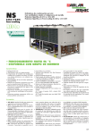
High Performance Vector Control Inverter
NEW
High performance enabled by the comprehensive use of Fuji technology.
Easy maintenance for the end-user.
Maintains safety and protects the environment.
Opens up possibilities for the new generation.
MEH659
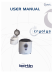
The Dawn of a New Era
The FRENIC-VG is ushering in a new era with the best performance in the industry.
NEW
High performance enabled by the comprehensive use of Fuji technology.
Easy maintenance for the end-user.
Maintains safety and protects the environment.
Opens up possibilities for the new generation.
With the FRENIC-VG, Fuji has concentrated its technologies to deliver the best-performing
inverter on the market. In addition to basic performance, this model features the following
dramatic improvements: support for previously difficult applications due to technical and
capability limitations, easier, more user-friendly maintenance, and environmental friendliness
and safety. Fuji Electric proudly introduces the FRENIC-VG to the world.
─2─
Easier maintenance and greater reliability
■ Quicker adjustment, start,
■ Fault diagnosis
replacement, and restoration times Trace back, clock function, and fault information
USB port, high functional loader, compatibility
■ Reliability
with earlier models, and ASR auto tuning
Individual output of serious and minor alarms, long-life
parts, and PG fault detection function
Environmental friendliness and safety
■ Conformity to functional safety standards ■ Environmental resistance
(Standard: STO incorporated) (Option: STO, SS1, SLS, and SBC can be incorporated)
RoHS (standard), durable against salt corrosion and
sulfidizing gas
■ Supports harmonics suppression (12-pulse rectification)
(Applicable capacity: supports the capacity of 132 kW or higher for each unit)
─3─
Terminal External Dimensions Dedicated Motor External Protective
Common
Standard
Functions of Dedicated Motors Specifications Dimensions Functions Specifications Specifications
Wiring
Diagram
■ Synchronous motor drive
■ Various optional cards supported (20 types or more)
■ Triple ratings available on intended use
■ Servo function
Names and
Terminal
Functions of KEYPAD Arrangement Diagram
A wide range of applications
Function Setting
■ High overload resistance (200% 3sec) ■ Low torque ripple
■ Improved torque accuracy (±3%) ■ Improved sensorless control performance (torque increased at low speed)
■ Improved quick response (600Hz) ■ Improved auto tuning accuracy
Options
Improved control capacity
Guideline for
Delivery Period
Wiring
Warranty
Suppressing Harmonics
and Code
Equipment
CONCEPT
Improved Control Performance
Materialized industry’
s best control performance
Induction Motor
Achieved speed response
of 600Hz
(Tested with a dedicated motor with PG under vector control with speed sensor: about six times greater than our conventional model)
Follow-up characteristics
under impact load
25.0
dB
dBMg
Torque current
command value
-25.0
dB 1
10
100
100%
1000
Frequency Hz
Actual speed
value
0.0
deg
100r/min
Motor current
Phase
(deg)
-360
deg 1
10
100
0.5s
1000
Load ON
(100%)
Frequency Hz
Load OFF
(0%)
FRN7.5VG1S-2J(600Hz, -3dB)
FRN37VG1S-4J, at 500r/min operation
FRN7.5VG7S-2(105Hz, -3dB)
FRN7.5VG5S-2(54Hz, -3dB)
Uneven rotation
Reduced by one-third*
Speed and torque characteristics
*Compared to our conventional model
Torque accuracy ±3%
FRN37VG1S-4J
0.5r/min
Conventional model (FRN37VG7S-4)
Axial torque (%)
150
0.5r/min
100
50
0
1000
2000
-50
-100
-150
At 30r/min operation
FRN37VG1S-4J
─4─
3000
Rotation
(r/min)
A Wide Range of Applications
Ratings for intended use
The operation mode for the motor is selected according to motor load condition. Motors larger by one or two frames can
be driven with medium load (MD) and light load (LD) use.
Specification
Applied load
HD
High Duty Spec (standard)
Powerful drive at low noise
Current: 150% 1min/200% 3sec
Middle Duty Spec
Can drive motors of frames one size larger *1
Current: 150% 1min, carrier 2kHz *2
Low Duty Spec
Can drive motors of frames one or two sizes larger *1
Current: 120% 1min
MD*3
LD
Feature
Applicable overload rating
(Notes) *1: Varies depending on the motor specification and power supply voltage.
*2: This will increase noise. Check the motor installation environment.
*3: The MD specification comes with only 400V series (90 to 400 kW). Multi-drive function
Capacity range expanded of brake circuit
Having a standard built-in brake circuit (with 200V 55kW or less and 400V
160KW or less), is useful when applying the inverter to the vertical transfer
machine, which is frequently used under the regenerative load.
Servo function
(Induction and synchronous motors)
- Highly efficient drive is achieved in driving together with our synchronous motor.
- Settings allow you to switch between induction and synchronous motor operation.
(coming soon)
The following functions are enabled.
- Position control by built-in APC
- The ABS encoder I/F option card with 17-bit high resolution
has been prepared.
This is soon to be supported for position control.
- Pulse column input enabled (optional)
- The SX and E-SX bus I/F option card has been prepared.
This is soon to be supported for position control.
GNF2 series
GNB2 series
GNS1 series
Synchronous motor
Induction motor
Sensor
provided
MVK series
Sensorless
──
GNF2 series
(Coming soon)
GNB2 series
GNS1 series (High efficiency)
A wide range of options
- The new model offers options that enable various interfaces, including high-speed communication.
- Options can be used by just inserting them into the connectors inside the inverter. Up to five cards can be mounted.
(There are some restrictions on how optional cards may be combined. Contact Fuji for details)
Type
Name
Analog card
Digital card (for 8-bit bus)
Type
Synchronized interface*1
OPC-VG1-SN
F/V converter*1
OPC-VG1-FV
Aio expansion card
OPC-VG1-AIO
Ai expansion card
OPC-VG1-AI
Di interface card
OPC-VG1-DI
OPC-VG1-DIO
Dio expansion card
PG interface expansion card
NEW
PG card for synchronous motor drive
Digital card (for 16-bit bus)
NEW
Safety card
Field bus interface card
Control circuit terminal
NEW
+5V line driver
OPC-VG1-PG
Open collector
OPC-VG1-PGo
(NEW) ABS encoder with 17-bit high resolution
OPC-VG1-SPGT
Line driver
OPC-VG1-PMPG
Open collector
OPC-VG1-PMPGo
T-Link interface card
OPC-VG1-TL
CC-Link interface card
OPC-VG1-CCL
SX bus interface card
OPC-VG1-SX
E-SX bus interface card
OPC-VG1-ESX
User programming card*1
OPC-VG1-UPAC
Functional safety card
OPC-VG1-SAFE
PROFIBUS-DP interface card*1
OPC-VG1-PDP
DeviceNet interface card*1
OPC-VG1-DEV
Terminal block for high-speed serial communications
OPC-VG1-TBSI
*1 Coming soon
─5─
Easier Maintenance and Greater Reliability
Upgraded PC loader functions
FRENIC-VG Loder can be used via the USB connector (mini B) equipped on the front cover.
FRENIC-VG
USB Mini B
connector
PC
- The front cover does not have to be removed.
- No RS-485 converter is needed.
USB cable
Connected/disconnected
enabled from the front
- Commercial cables can be used.
【Fault diagnosis using the trace back function】 【Easy edit and detail monitor】
Data editing and detailed data monitor analysis operations
are must easier than with a conventional PC loader.
Edited on the trace screen on the loader
Function code setting User-defined displays (customized displays),
data explanation display for each code.
Trace function Real-time trace: for long-term monitoring
Historical trace: for detailed data diagnosis for short periods
Trace back: for fault analysis (last three times)
- Internal data and date around the fault are recorded. NEW The real-time clock (clock function) is built-in as standard.
- Data are backed up by battery.
(Note) Real-time and historical traces are available in the fare-paying loader software (WPS-VG1-PCL).
The trace data can be stored in the internal memory even when the power is shut off (for inverters
with 22kW or less, this function is available using the optional battery for memory backup).
(NOTE) Battery: 30kW or more (built-in as standard), up to 22kW (available as option:OPK-BP)
- Trace waveform can be checked on the PC loader
Multifunctional KEYPAD
- Remote control operation is available.
- Wide 7-segment LED ensures easy view.
- Backlighted LCD display allows the operator to see
the display clearly, even on a dark control panel.
- NEW Enhanced copy function
The function codes can be copied to other inverters easily.
(Three patterns of function codes can be stored.) Copying
data in advance reduces restoration time when problems
occur, by replacing the KEYPAD when changing the unit.
The KEYPAD can be remotely operated by
extending the cable length at the RJ connector.
- JOG (jogging) operation can be executed using
the KEYPAD.
-
NEW
The HELP key displays operation guidance.
More reliable functions
Alarm severity selection
Save alarm data
Detailed data are stored for the
last four alarms, including:
-
OU
Occurrence time
2011/01/01
12:
36:45
Occurrence
time
Alarm severity (serious and minor) can be selected, eliminating the
risk of critical facility stoppage due to a minor fault.
OC
2011/01/01
LU
Time to sound alarm
12:
36:45 N* =1500.0r/m
Occurrence
time
Speed setting value
N =1500.0r/m
2011/01/02
OC
f * =50.0Hz
12:
36:45 N* =1500.0r/m
Detection speed value Occurrence
time
TRQ= 90%
N =1500.0r/m
2011/01/05
Torque command value
f *=50.0Hz
12:36:45 N* =1500.0r/m
TMP = 43℃
Temperature
TRQ= Iout
90%= 251.6A
N =1500.0r/m
Vout 35℃
= 190V
f *=50.0Hz
(heat sink, internal temperature) N* =1500.0r/m
TMP = TRQ= 90% FLX* = 100%
Accumulated operation time N =1500.0r/m Iout = 256.2A
Vout 55℃
= 200V
f *=50.0Hz
TMP = Output current detection value TRQ= Iout
FLX*
= 100%
90%= 180.0A
Vout 45℃
= 132V
Magnetic-flux reference value TMP = FLX*
= 100%
Iout = 210.6A
I/O status
Vout = 160V
FLX* = 100%
NEW The number of alarm data to be stored has been increased
- from the conventional model.
With the real-time clock function built-in as standard, the latest and the last
three pieces of alarm data on time, speed command, torque, current and others
can be stored. This enables machine units to be checked for abnormalities.
⇒Previously alarm data were deleted to overwrite spin-off alarm
data. This is resolved with the new VG model.
30-relay Y-terminal
output
output
Motor overload,
communications error,
DC fan lock, etc.
Blown fuse, excessive current,
ground fault, etc.
Not output
Provided
(minor fault)
Inverter
output
Selection
Output
None
Operation
continued Can be selected
for each function.
Shutoff
Output
None
Shutoff
Fixed
PG fault diagnosis
NEW
- The
PG interface circuit incorporated as standard detects
disconnection of the power supply line as well as the PG signal line.
- Operation can be continued in sensorless mode during PG
disconnection or fault. (Soon to be supported)
Old model: The inverter was stopped by a trip and the motor runs freely.
New model: The mode is automatically switched to sensorless vector control mode when
a PG fault is detected, minimizing effect to the machined products.
(Control performance during the sensorless control is lower than with PG vector control. Check operating conditions in advance
by combining the sensorless mode to your units or machines to see whether the torque applied at low speed is sufficient or not.)
NEW
- A
mode that judges if it is a PG fault or fault on the inverter side was added
Simulated output mode is provided at the PG pulse output terminal (FA and
FB). Operation can be checked by connecting this to the PG input terminal.
─6─
Components with a longer service life
For the various consumable parts inside the inverter, their designed lives have been
extended to 10 years, which also extended the equipment maintenance cycles.
Life-limited component name
Enhanced lifetime alarm
- Lifetime alarms can be checked readily on the KEYPAD
and the PC loader (optional).
- Facility maintenance can be performed much easier thanks to lifetime alarms.
Planned life
Cooling fan
Smoothing capacitor on main circuit
Items
10 years
Inverter accumulated No. of inverter
time (h)
starts (times)
Electrolytic capacitors on PCB
Facility maintenance warning
Accumulated time (h)
No. of starts (times)
Inverter lifetime alarm
information is displayed.
Life conditions
Ambient temperature: 40゜
C, load factor: 100% (HD spec), 80% (MD and LD specs)
(Note) The planned life is determined by calculation, and is not a guaranteed value.
Useful functions for test run and adjustment
Easy wiring (removable control terminal block)
- The terminal block can be connected to the inverter after
control wiring work is complete. Wiring work is simplified.
- Customization of function code display
(Individual items on the loader can be set to display or not.)
- Each communications I/O map input/output status is displayed (for PLC software
debug) on the loader or KEYPAD (KEYPAD is soon to be supported).
- Restoration time for updating equipment, problem occurrence,
and inverter replacement has been drastically reduced. Just
mount the wired terminal block board to the replaced inverter.
NEW
- Simulated
fault alarm issued by a special operation on the KEYPAD
NEW
- Monitor
data hold function
- Simulated operation mode
Simulated connection allows the inverter to be operated with internal parts in the
same way as if they were connected to the motor, without actually being connected.
- The externally input I/O monitor and PG pulse states can
be checked on the KEYPAD.
- ASR auto tuning (Soon to be supported)
Adaptation to Environment and Safety
Conforms to safety standards (Soon to be supported)
Enhanced environmental resistance
- The safety function STO that conforms to the function
safety standard EN61800-5-2 is incorporated as standard.
- The safety functions STO, SS1, SLS, and SBC that conform to safety
standard EN61800-5-2 can be incorporated by adding the function safety
option OPC-VG1-SAFE. (Available only when combined with the dedicated motor MVK.)
Safety function STO: Safe Torque Off
This function shuts down the output of torque with the motor immediately.
Safety function SS1: Safe Stop 1
This function decreases the motor speed to shut down the motor by
torque output OFF by the STO function immediately when the motor
reaches the specified speed or after the specified time has elapsed.
Safety function SLS: Safely Limited Speed
This function prevents the motor from rotating over the specified speed.
Environmental resistance has been enhanced compared to conventional inverters.
(1) Environmental resistance of cooling fan has been enhanced.
(2) Ni and Sn coatings are employed on copper bars.
Environmental resistance has been enhanced on the FRENIC-VG
compared to conventional models; however, the following environments
should be examined based on how the equipment is being used.
a.
Sulfidizing gas
(used as a part of the business such as with tire
manufacturers, paper manufacturers, sewage treatment, and the textile industry)
b.
Conductive dust and foreign particles (such
as with metal
processing, extruding machines, printing machines, and waste treatment)
c.Others: under unique environments not included under standard environments
Contact Fuji before using the product in environments such as
those indicated above.
Safety function SBC: Safe Brake Control
This functions outputs signals the control the motor brake.
RoHS Directive compliance
VG complies with European regulations that limit the use of specific hazardous substances (RoHS) as a standard.
Six hazardous substances
About RoHS
Lead, mercury, cadmium, hexavalent chromium, polybrominated
biphenyl (PBB), and polybrominated biphenyl ether (PBDE)
(Note)Does not apply to the parts of some inverter models.
─7─
Directive 2002/95/EC, promulgated by the European Parliament
and European Council, limits the use of specific hazardous
substances included in electrical and electronic devices.
Application Examples
Large crane and
overhead crane
Application to plants
Electric room
Operation
room
Container
Monitoring room
Travel equipment
Control with high speed and high accuracy
High reliability
In addition to high speed and high accuracy, VG contributes to stable facility
operation with high reliability and long service life. The trace back function
makes diagnosing the cause of problems easy when an abnormality arises.
VG supports your facility with long life service and
high reliability.
The trace back function allows easy fault diagnosis.
System support
System support
Centralized control and monitoring are achieved by
supporting various fieldbuses.
The bus system is supported to allow centralized
control of elevation, traverse, and trolley, as well as
centralized monitoring of running conditions.
Servo press: large size for automobiles, small size for
machines such as crimping terminal processing machines
Winding equipment
(paper and metal)
Tension control
Position control
Tension-type winding control capability with high accuracy torque control has been improved.
Dancer-type winding control capability by the speed control with high speed response has
been improved.
The press position is controlled based on an instantaneous position command
given by the CNC of the high order.
Control with high responsibility contributes to shortening of the operation cycle.
System support
Precision synchronization control
The controller that calculates winding diameter achieves
constant tension control.
Large machines are driven with several motors to increase thrust.
Precision synchronization control of several inverters and motors
using the high-speed bus system can be applied.
─8─
Feeding part of semiconductor
manufacturing device, wire saw
M
Feed
Test equipment
for automobiles
Winding up
Material
M
Dancer
M
Traverse
M
M
M
Dancer
M
Traverse
Spindle
M
Winding off
High-speed response control
Smooth torque characteristic
High-speed rotation and torque control with high
response are available for engine and transmission
tests.
The smooth drive characteristic in which torque ripple
is suppressed contributes to machining quality.
System support
System support
The system can be supported in cases such as the
vehicle body inertia simulation function for a brake test
apparatus by combining with the controller.
The system has been made simple and highly efficient by connecting and
controlling the spindle that drives wires and the small-capacity servo that
drives the traverse axis and winding up and off axes in the same bus system.
Shipboard winch
Flying shear
(Cutting while moving)
Position control
High reliability and tension control
Position control is performed according to the position
command given by the high-order CNC. The machine cuts
the blank while moving at the same speed as the blank.
Torque is controlled up to extra low speed using the
sensorless feature.
Stable drive is maintained against load variation
caused by waves.
System support
The system is configured by a controller that
calculates synchronous operation among the blank
feed axis, cutter feed axis and cut axis.
─9─
Variation
200V Series
Nominal applied
motor
(kW)
400V Series
HD
(150% 1min.,200% 3sec.)
LD
(120% 1min.)
HD
(150% 1min.,200% 3sec.)
MD
(150% 1min.)
LD
(120% 1min.)
Applied load
High Duty Spec
Low Duty Spec
High Duty Spec
Middle Duty Spec
Low Duty Spec
0.75
FRN0.75VG1S-2J
1.5
FRN1.5VG1S-2J
2.2
FRN2.2VG1S-2J
3.7
FRN3.7VG1S-2J
FRN3.7VG1S-4J
5.5
FRN5.5VG1S-2J
FRN5.5VG1S-4J
7.5
FRN7.5VG1S-2J
FRN7.5VG1S-4J
11
FRN11VG1S-2J
FRN11VG1S-4J
15
FRN15VG1S-2J
FRN15VG1S-4J
18.5
FRN18.5VG1S-2J
FRN18.5VG1S-4J
22
FRN22VG1S-2J
FRN22VG1S-4J
30
FRN30VG1S-2J
37
FRN37VG1S-2J
FRN30VG1S-2J
FRN37VG1S-4J
FRN30VG1S-4J
45
FRN45VG1S-2J
FRN37VG1S-2J
FRN45VG1S-4J
FRN37VG1S-4J
55
FRN55VG1S-2J
FRN45VG1S-2J
FRN55VG1S-4J
FRN45VG1S-4J
75
FRN75VG1S-2J
FRN55VG1S-2J
FRN75VG1S-4J
FRN55VG1S-4J
90
FRN90VG1S-2J
FRN75VG1S-2J
FRN90VG1S-4J
FRN90VG1S-2J
FRN110VG1S-4J
FRN90VG1S-4J
FRN90VG1S-4J
132
FRN132VG1S-4J
FRN110VG1S-4J
FRN110VG1S-4J
160
FRN160VG1S-4J
FRN132VG1S-4J
FRN132VG1S-4J
200
FRN200VG1S-4J
FRN160VG1S-4J
FRN160VG1S-4J
220
FRN220VG1S-4J
FRN200VG1S-4J
FRN200VG1S-4J
110
FRN30VG1S-4J
FRN75VG1S-4J
FRN220VG1S-4J
250
FRN220VG1S-4J
280
FRN280VG1S-4J
315
FRN315VG1S-4J
FRN280VG1S-4J
355
FRN355VG1S-4J
FRN315VG1S-4J
FRN280VG1S-4J
400
FRN400VG1S-4J
FRN355VG1S-4J
FRN315VG1S-4J
FRN400VG1S-4J
FRN355VG1S-4J
450
500
FRN500VG1S-4J
FRN400VG1S-4J
630
FRN630VG1S-4J
FRN500VG1S-4J
FRN630VG1S-4J
710
*When a motor which is larger than the inverter by one frame or more for FRN55VG1□-2J/4J or higher inverters (applicable motor 75kW or more),
the type of DC reactor, which is a standard accessory, is different among HD, MD and LD specifications. (Shifted by one frame)
How to read the model number
FRN 5.5 □ VG 1 S - 2 J □□
Special type
Code
FRN
Series name
FRENIC Series
Code
0.75
1.5
2.2
3.7
5.5
Nominal applied motor capacity
0.
75kW
1.
5kW
2.
2kW
3.
7kW
5.5kW
∼
∼
630
630kW(HD)
710kW(LD)
Code
None
Cabinet
Unit type
Code
VG
Application range
High performance vector control
Code
J
E
C
Z
Language
Japanese
English
Chinese
Optional language
Code
2
4
Input power source
Three-phase 200V
Three-phase 400V
Code
S
Structure
Standard
Code
1
Developed inverter series
Series
(Note) Built-in options: Not provided, braking relation: The standard specification type shown in above list is employed for the standard model.
The product detail described in this document is intended for selecting a model. When using a product, read the Instruction Manual carefully
Caution! and use the product properly.
─ 10 ─
Three-phase 200V series (unit type)
Input power
Overload current rating
3.7
5.5
7.5
11
15
18.5
22
30
37
45
55
75
90
0.75
1.5
2.2
3.7
5.5
7.5
11
15
18.5
22
30
37
45
55
75
90
1.9
3.0
4.1
6.8
10
14
18
24
28
34
45
55
68
81
107
131
5
8
11
18
27
37
49
63
76
90
119
146
180
215
283
346
150% of rated current -1min. (*2) 200% -3sec. (*3)
Main power
Phase, Voltage, Frequency
3-phase 200 to 230V,50Hz/60Hz
Auxiliary input for control power
Phase, Voltage, Frequency
Single phase 200 to 230V,50Hz/60Hz
Auxiliary input for fan power
Phase, Voltage, Frequency (*5)
3-phase 200 to 220V/50Hz,
200 to 230V/60Hz (*4)
Single phase 200 to 220V/50Hz,
200 to 230V/60Hz (*4)
ー
Voltage/frequency variation
Voltage: +10 to -15% (Voltage unbalance: 2% or less (*6)), Frequency: +5 to -5%
Rated current [A] (with DCR)
(*7)
(without DCR)
3.2
6.1
8.9
15.0 21.1
28.8
42.2
57.6 71.0
84.4
114
138 167
203
282
5.3
9.5
13.2
22.2 31.5
42.7
60.7
80.1 97.0
112
151
185 225
270
−
−
Required power supply capacity [kVA] (*8)
1.2
2.2
3.1
10
15
30
40
71
98
116
5.2
7.4
20
25
48
58
334
Braking method /braking torque
Braking resistor discharge control: 150% braking torque, Separately installed braking resistor (option), Separately installed braking unit (option for FRN75VG1S-2J or higher)
Carrier frequency [kHz] (*9)
2 to 15
Approx. weight [kg]
6.2
Enclosure
IP20 closed type
2 to 10
6.2
6.2
6.2
6.2
6.2
11
11
11
12
25
32
42
43
62
105
IP00 open type (IP20 closed type is available as option)
Three-phase 400V series (unit type)
Type FRN□VG1S-4J
3.7
5.5
7.5
11
15
18.5 22
30
37
45
55
Nominal applied motor [kW]
3.7 5.5
7.5
11
15 18.5 22
30
37
45
Rated capacity [kVA] (*1)
6.8
14
18
24
45
57
69
10
29
34
75
90
110 132 160 200
220 280 315 355 400 500 630
55
75
90
110 132 160 200 220 280 315 355 400 500 630
85
114 134 160 192 231 287 316 396 445 495 563 731 891
9.0 13.5 18.5 24.5 32.0 39.0 45.0 60.0 75.0 91.0 112 150 176 210 253 304 377 415 520 585 650 740 960 1170
Overload current rating
150% of rated current -1min. (*2) 200% -3sec. (*3)
Main power
Phase, Voltage, Frequency
3-phase 380 to 480V,50Hz/60Hz
Auxiliary input for control power
Phase, Voltage, Frequency
Single phase 380 to 480V,50Hz/60Hz
Auxiliary input for fan power
Phase, Voltage, Frequency (*5)
3-phase 380 to 440V/50Hz,
380 to 480V/60Hz (*4)
Terminal
Arrangement Diagram
Input power
Rated current [A]
Single phase 380 to 440V/50Hz,
380 to 480V/60Hz (*4)
ー
Voltage/frequency variation
Voltage: +10 to -15% (Voltage unbalance: 2% or less (*6)), Frequency: +5 to -5%
Rated current [A] (with DCR)
(without DCR)
(*7)
7.5 10.6 14.4 21.1 28.8 35.5 42.2 57.0 68.5 83.2 102 138 164 210 238 286 357 390 500 559 628 705 881 1115
Required power supply capacity [kVA] (*8)
Braking method /braking torque
13.0 17.3 23.2 33 43.8 52.3 60.6 77.9 94.3 114 140
−
−
−
−
−
−
−
−
−
−
−
−
−
5.2 7.4 10 15 20 25 30 40 48 58 71 96 114 140 165 199 248 271 347 388 436 489 610 773
Braking resistor discharge control: 150% braking torque, Separately installed braking resistor (option), Separately installed braking unit (option for FRN200VG1S-4J or higher)
Carrier frequency [kHz] (*9)
2 to 15
Approx. weight [kg]
6.2
Enclosure
IP20 closed type
6.2 6.2
2 to 10
11
11
11
11
25
26
31
33
42
62
2 to 5
64
94
98 129 140 245 245 330 330 555 555
IP00 open type (IP20 closed type is available as option)
Note 1) The specifications above are established when the function code F80 = 0 (HD specification) is applied. When used with the HD specification with 75kW or more, the DC
Reactor is provided as standard.
*1) The rated output voltage is 220V for 200V series and 440V for 400V series.
*2) When the inverter output frequency converter value is 10Hz or less, the inverter may trip early due to overload depending on the conditions such as ambient temperature.
*3) When the inverter output frequency converted value is 5Hz or less, the inverter may trip early due to overload depending on the conditions such as ambient temperature.
*4) 200V series: Make an individual order for 220 to 230V/50Hz.
400V series: The inverters with the power supply of 380 to 398V/50Hz and 380 to 430V/60Hz must be switched with the connector inside the inverter. The output of the
inverter with 380V may drop depending on situations. For the detail, refer to the FRENIC-VG User Manual 10.5.
*5) The auxiliary power input is used as an AC fan power input when combining the unit such as high power factor PWM converter with power regenerative function. (Generally not used.)
*6) Voltage unbalance [%] = (Max. voltage [V] - Min. voltage [V])/Three-phase average voltage [V] × 67
Use the AC reactor if the voltage unbalance exceeds 2%.
*7) The value is calculated on assumption that the inverter is connected with a power supply capacity of 500kVA (or 10 times the inverter capacity if the inverter capacity exceeds 50kVA) and %X is 5%.
*8) This shows values when the DC reactor is used. (Optional for 55kW or less model)
*9) The inverter may automatically reduce carrier frequency in accordance with ambient temperature or output current in order to protect itself.
─ 11 ─
Names
Rated current [A]
2.2
Functions of KEYPAD
Function Setting
Rated capacity [kVA] (*1)
1.5
Options
Nominal applied motor [kW]
0.75
Guideline for
Delivery Period
Wiring
Warranty
Suppressing Harmonics
and Code
Equipment
Type FRN□VG1S-2J
Wiring
Diagram
HD specification for high duty spec
Terminal External Dimensions Dedicated Motor External Protective
Common
Standard
Functions of Dedicated Motors Specifications Dimensions Functions Specifications Specifications
Standard Specifications
Standard Specifications
MD specification for middle duty spec
Three-phase 400V series
Type FRN□VG1S-4J
90
110
132
160
200
220
280
315
355
400
Nominal applied motor [kW] (*7)
110
132
160
200
220
250
315
355
400
450
Rated capacity [kVA] (*1)
160
192
231
287
316
356
445
495
563
640
Rated current [A]
210
253
304
377
415
468
585
650
740
840
Input power
Overload current rating
150% of rated current -1min.
Main power
Phase, Voltage, Frequency
3-phase 380 to 440V/50Hz,
380 to 480V/60Hz (*2)
Auxiliary input for control power
Phase, Voltage, Frequency
Single phase 380 to 480V, 50Hz/60Hz
Auxiliary input for fan power
Phase, Voltage, Frequency (*3)
Single phase 380 to 440V/50Hz,
380 to 480V/60Hz (*2)
Voltage/frequency variation
Voltage: +10 to -15% (Voltage unbalance: 2% or less (*4)), Frequency: +5 to -5%
Rated current [A] (with DCR)
(without DCR)
(*5)
Required power supply capacity [kVA] (*6)
Braking method /braking torque
210
238
286
357
390
140
165
199
248
Braking resistor discharge control: 150%
braking torque,
Separately installed braking resistor (option)
Enclosure
559
628
705
789
271
312
388
436
489
547
Braking resistor discharge control: 150% braking torque,
Separately installed braking resistor (option),
Separately installed braking unit (option)
2
Carrier frequency [kHz]
Approx. weight [kg]
443
ー
62
64
94
98
129
140
245
245
330
330
IP00 open type (IP20 closed type is available as option)
Note 1) The specifications above are established when the function code F80 = 3 (MD specification) is applied. When used with the MD specification with 90kW or more, the DC
Reactor is provided as standard.
*1) Inverter output capacity [kVA] at 440V.
*2) The inverters with the power supply of 380 to 398V/50Hz and 380 to 430V/60Hz must be switched with the connector inside the inverter.
*3) The auxiliary power input is used as an AC fan power input when combining the unit such as high power factor PWM converter with power regenerative function. (Generally not used.)
*4) Voltage unbalance [%] = (Max. voltage [V] - Min. voltage [V])/Three-phase average voltage [V] × 67
Use the AC reactor if the voltage unbalance exceeds 2%.
*5) The value is calculated on assumption that the inverter is connected with a power supply capacity of 10 times the inverter capacity and %X is 5%.
*6) This shows values when the DC reactor is used.
*7) Since heat generation of the motor due to low carrier may be increased depending on the load condition, designate the MD specification when ordering the motor.
─ 12 ─
30
37
45
Nominal applied motor [kW]
37
45
55
Rated capacity [kVA] (*1)
55
68
81
146
180
215
283
75
90
110
107
131
158
346
415
120% of rated current -1min.
3-phase 200 to 220V/50Hz,
200 to 230V/60Hz (*2)
Auxiliary input for control power
Phase, Voltage, Frequency
Single phase 200 to 230V, 50Hz/60Hz
Auxiliary input for fan power
Phase, Voltage, Frequency (*3)
Single phase 200 to 220V/50Hz,
200 to 230V/60Hz (*2)
ー
Voltage: +10 to -15% (Voltage unbalance: 2% or less (*4)), Frequency: +5 to -5%
Rated current [A] (with DCR)
(*5)
(without DCR)
Required power supply capacity [kVA] (*6)
138
167
203
282
334
185
225
270
−
−
410
−
48
58
71
98
116
143
Braking method /braking torque
Braking resistor discharge control: 110% braking torque, Separately installed braking resistor (option), Separately installed braking unit (option for FRN75VG1S-2J or higher)
Carrier frequency [kHz] (*7)
2 to 10
Approx. weight [kg]
Enclosure
2 to 5
25
32
42
43
62
105
IP00 open type (IP20 closed type is available as option)
Three-phase 400V series
30
37
45
Nominal applied motor [kW]
37
45
55
Rated capacity [kVA] (*1)
57
69
85
Rated current [A]
75
91
112
150
Overload current rating
120% of rated current -1min.
55
75
90
110
132
160
200
220
280
315
355
400
500
630
75
90
110
132
160
200
220
280
355
400
450
500
630
710
114
134
160
192
231
287
316
396
495
563
640
731
891 1044
176
210
253
304
377
415
520
650
740
840
960 1170 1370
881 1115 1256
Main power
Phase, Voltage, Frequency
3-phase 380 to 480V,
50Hz/60Hz
Auxiliary input for control power
Phase, Voltage, Frequency
Single phase 380 to 480V, 50Hz/60Hz
Auxiliary input for fan power
Phase, Voltage, Frequency (*3)
Voltage/frequency variation
Rated current [A] (with DCR)
(without DCR)
(*5)
Required power supply capacity [kVA] (*6)
Braking method /braking torque
3-phase 380 to 440V/50Hz,
380 to 480V/60Hz (*2)
Terminal
Arrangement Diagram
Input power
Type FRN□VG1S-4J
Single phase 380 to 440V/50Hz,
380 to 480V/60Hz (*2)
ー
Voltage: +10 to -15% (Voltage unbalance: 2% or less (*4)), Frequency: +5 to -5%
68.5 83.2
102
138
164
210
238
286
357
390
500
628
705
789
94.3
114
140
ー
ー
ー
ー
ー
ー
ー
ー
ー
ー
ー
ー
ー
ー
48
58
71
96
114
140
165
199
248
271
347
436
489
547
611
773
871
Braking resistor discharge control: 110% braking torque, Separately installed braking resistor (option), Separately installed braking unit (option for FRN200VG1S-4J or higher)
Carrier frequency [kHz] (*7)
2 to 10
Approx. weight [kg]
25
Enclosure
IP00 open type (IP20 closed type is available as option)
26
2 to 5
31
33
42
2
62
64
94
98
129
140
245
245
330
330
555
555
Note 1) The specifications above are established when the function code F80 = 1 (LD specification) is applied. When used with the LD specification with 55kW or more, the DC
Reactor is provided as standard.
*1) The rated output voltage is 220V for 200V series and 440V for 400V series.
*2) 200V series: Make an individual order for 220 to 230V/50Hz.
400V series: When the input voltage is 380 to 398V/50Hz or 380 to 430V/60Hz, the connector inside the inverter must be switched.
*3) The auxiliary power input is used as an AC fan power input when combining the unit such as high power factor PWM converter with power regenerative function. (Generally not used.)
*4) Voltage unbalance [%] = (Max. voltage [V] - Min. voltage [V])/Three-phase average voltage [V] × 67
Use the AC reactor if the voltage unbalance exceeds 2%.
*5) The value is calculated on assumption that the inverter is connected with a power supply capacity of 500kVA (or 10 times the inverter capacity if the inverter capacity exceeds
50kVA) and %X is 5%.
*6) This shows values when the DC reactor is used. (Optional for FRN45VG1S-2J and FRN45VG1S-4J or lower model)
*7) The inverter may automatically reduce carrier frequency in accordance with ambient temperature or output current in order to protect itself.
─ 13 ─
Names
Main power
Phase, Voltage, Frequency
Voltage/frequency variation
90
Functions of KEYPAD
Function Setting
Input power
Overload current rating
75
Options
Rated current [A]
55
Guideline for
Delivery Period
Wiring
Warranty
Suppressing Harmonics
and Code
Equipment
Type FRN□VG1S-2J
Terminal External Dimensions Dedicated Motor External Protective
Common
Standard
Functions of Dedicated Motors Specifications Dimensions Functions Specifications Specifications
Three-phase 200V series
Wiring
Diagram
LD specification for low duty spec
Common Specifications
Common specifications for inverters
Item
Specifications
Vector control w/ speed sensor
For induction motor
Control
Motor control
Speed sensorless vector control
V/f control
method
For synchronous motor
Vector control w/ speed sensor (including magnetic pole position detection)
Test mode
Simulated operation mode
Speed setting
Analog setting: ±0.005% of max. speed
Digital setting: ±0.005% of max. speed
Setting resolution
Torque setting
Torque current setting
Speed
Induction motor
Vector control
control
w/ speed sensor
Control accuracy
Control response
0.01% of rated torque
Analog setting: ±0.1% of max. speed (25±10°
C)
Digital setting: ±0.005% of max. speed (-10 to 50°
C)
Torque
±3% of rated torque (w/ dedicated motor)
Speed
600Hz *1
Maximum speed
800Hz by inverter output frequency conversion *1
Speed control range
When the base speed is 1500 r/min, 1 to 1500 r/min to max. speed (w/ no. of PG pulses is 1024P/R)
1:1500 1:6 (constant torque range: constant output range)
Speed setting
Analog setting: ±0.005% of max. speed
Digital setting: ±0.005% of max. speed
Setting resolution
Torque setting
0.01% of rated torque
Torque current setting
Speed
Speed sensorless
Control accuracy
vector control
Control response
Digital setting: ±0.1% of max. speed (-10 to 50°
C)
Torque
±5% of rated torque
Speed
40Hz *1
Maximum speed
Induction motor
Analog setting: ±0.1% of max. speed (25±10°
C)
500Hz by inverter output frequency conversion *1
1:250
control
Speed control range
When the base speed is 1500 r/min, 6 to 1500 r/min to max. speed
1:4 (constant torque range: constant output range)
Setting resolution
V/f control
Output frequency control accuracy
Maximum frequency
Control range
Speed setting
Setting resolution
Torque setting
Synchronous motor
Vector control
control
w/ speed sensor
Speed
Control accuracy
Response control
Analog setting: ±0.005% of max. speed
Digital setting: ±0.005% of max. speed
Analog setting: ±0.2% of max. output frequency (25±10°
C)
Digital setting: ±0.01% of max. output frequency (-10 to 50°
C)
500Hz
0.2 to 500Hz
1:4 (constant torque range: constant output range)
Analog setting: ±0.005% of max. speed
Digital setting: ±0.005% of max. speed
0.01% of rated torque
Analog setting: ±0.1% of max. speed (25±10°
C)
Digital setting: ±0.005% of max. speed (-10 to 50°
C)
Torque
±3% of rated torque (w/ dedicated motor)
Speed
600Hz *1
Maximum speed
800Hz by inverter output frequency conversion *1
*1: Maximum value. This value may not be reached depending on the carrier frequency settings.
─ 14 ─
KEYPAD operation: CW or CCW operation by
or
key, and
key
Digital input signal operation: FWD or REV command, coast-to-stop command, reset input, multistep speed selection command, etc.
KEYPAD operation:
or
key
External potentiometer: three terminals, 1 to 5kΩ
Speed setting
Analog input:
0 to ±10V, 4-20mA
UP/DOWN control:
Speed increases when UP signal (DI) is ON,
Multistep speed:
Up to 15 different speeds can be selected by combining four external input signals (DI).
Serial link operation:
RS-485 (standard). Setting through different communication options is possible.
and decreases when DOWN signal (DI) is ON.
Jogging operation:
Induction motor:
or
key, or FWD or REV terminals in jogging mode
+15V, +12V complimentary output PG (insulated)
/ max. receivable frequency: 100kHz
+5V line driver output PG (insulated): w/ option card OPC-VG1-PG installed
/ max. receivable frequency: 500kHz
Synchronous motor: +5V line driver output PG (insulated)
Speed detection
<ABS type> W/ option card OPC-VG1-PMPG installed
/ max. receivable frequency: 100kHz
<ABZ type> W/ option card OPC-VG1-PG installed
/ max. receivable frequency: 500kHz
: ABS encoder with 17-bit high resolution (TS5667N253: made by Tamagawa Seiki) Servomotor serial PG
TS5667N253 (made by Tamagawa Seiki, 17bit/turn and 16bit/multi-turns), w/ option card OPC-VG1-SPGT installed
Control
The PI calculation w/ feed forward term is performed.
Speed control
Control invariable selection
The control invariable can be selected by eternal signals.
Running status signal
Acceleration/Deceleration time
Transistor output: Inverter running, Speed equivalence, Speed detection, inverter overload early warning, torque limiting, etc.
Analog output: Motor speed, Output voltage, Torque, Load factor, etc.
0.01 to 3600s (4 independent settings for acceleration and deceleration selectable with external signals)
(S-curve acceleration/deceleration in addition to linear acceleration/deceleration)
Gain for speed setting
Sets the proportional relationship between analog speed setting and motor speed in the range of 0 to 200%.
Jump speed
Jump speed (3 points) and jump hysteresis width (1 point) can be set.
Rotating motor pick up (Flying start)
A rotating motor can be smoothly picked up by the inverter without stopping.
Auto-restart after momentary power failure
Automatic restart is available without stopping the motor after a momentary power failure.
Slip compensation
Compensates for the decrease of speed due to load and realizes stable operation (by V/f control w/ induction motor).
Droop control
The motor speed droops in proportion to output torque (disabled with V/f control).
Torque limiting
Terminal External Dimensions Dedicated Motor External Protective
Common
Standard
Functions of Dedicated Motors Specifications Dimensions Functions Specifications Specifications
1 to 1500 r/min to max. speed
Wiring
Diagram
Running and operation
When the base speed is 1500 r/min,
Limits the torque to predetermined values (selectable from "common to 4 quadrants", "independent driving and braking", etc.)
Analog and external signal (2 steps) settings are available.
Torque control
Analog setting: 0 to ±10V /0 to ±150% (up to 300% by gain adjustment)
PID control
Analog input by PID control is possible.
Cooling fan ON/OFF control
Cooling fan is stopped during motor stoppage and low temperature to elongate the cooling fan life and reduce cooling fan noise.
Toggle monitor control
Monitors the communications between the host device (PLC) and the inverter are functioned in a proper condition.
─ 15 ─
Names
w/ speed sensor
Functions of KEYPAD
Function Setting
motor control
1:1500 (w/ no. of PG pulses is 1024P/R)
Speed control range
Options
Vector control
Guideline for
Delivery Period
Wiring
Warranty
Suppressing Harmonics
and Code
Equipment
Synchronous
Specifications
Terminal
Arrangement Diagram
Item
Common Specifications
Item
Internal setting (3 steps) and analog setting (hold function) are enabled by combining the fixed value
Torque bias
(1 step, polarity switching by motor rotation direction function) and eternal signal (DI signal).
Motor selection
Temperature detection
Control
NTC thermister (Fuji Electric product or equivalent item)
PTC thermister (trip level set by parameter) (for motor overheat protection)
Self-diagnosis for detection circuit of the pulse encoder input signal (PA, PB)
Load adaptive control function
Running efficiency of the unit can be improved by calculating the max. elevation speed achieved by the weight for a vertical transfer unit or other similar units.
Multiple winding motor drive
Option: OPC-VG1-TBSI
Reactor connection drive
Only for PG vector control and sensorless vector control
UP/DOWN control
Speed setting is possible by combining the UP command, DOWN command, and zero clear command using the external signal (DI signal).
Stopping function
3 types of stopping functions: STOP 1, 2 and 3.
Outputs the input pulse such as a motor PG signal by fixed or free frequency dividing.
Open collector and complimentary (same voltage as PGP terminal) can be switched by setting the unit internal switch.
Observer
Suppresses load disturbances and vibrations.
Off-line tuning
Rotary type and non-rotary type are available for tuning the motor constant.
On-line tuning
Used as a motor constant for compensating the temperature change.
Position control
Standard function: position control by servo lock and built-in transmitting circuit.
Options: OPC-VG1-PG (PR) : for line driver type pulse command input
OPC-VG1-PGo (PR) : for open collector type pulse command input
OPC-VG1-SPPG (PR): ABS encoder with 17-bit high resolution
Pulse train synchronous operation
setting
Motor can be selected from three types by using (F79) or by combining the eternal signal
(DI signal).
PG detection circuit self diagnosis
PG pulse output
Display and
Specifications
Options: OPC-VG1-PG (PR) : for line driver type pulse command input
OPC-VG1-PGo (PR) : for open collector type pulse command input
Display
7-segment LED, LCD w/ backlight
Language display
Japanese, English, Chinese, Korean (French, Spanish, German, and Italy *1)
Running/stopping
• Detected speed value
• Speed reference value
• Output frequency
• Torque reference value
• Torque calculation value • Power consumption (motor output)
• Output voltage
• DC link circuit voltage
• Magnetic-flux reference value
• Load shaft speed
• PID reference value
• PID feedback value
• Ai adjusted value (12)
• Ai adjusted value (Ai1)
• Ai adjusted value (Ai2)
• Presence of digital input/output signal
• Motor temperature
• Load factor
• Input power
• Integral power consumption
• Motor accumulated operation time/no. of starts (for each motor), etc.
Setting mode
Names and data are displayed.
KEYPAD
Alarm mode
Minor fault
• Torque current reference value
• Output current
• Magnetic-flux calculation value
• PID output value
• Optional monitor 1 to 6
• Heat sink temperature
• Operation time
Displays the following alarm codes;
・dbH (Braking resistance overheat) ・dCF (DC fuse blown) ・EF (Ground fault)
・Er1 (Memory error) ・Er2 (KEYPAD panel communication error)
・Er3 (CPU error) ・Er4 (Network error) ・Er5 (RS-485 error) ・Er6 (Operation procedure error) ・Er7 (Output wiring error)
・Er8 (A/D converter error)
・Er9 (Speed disagreement) ・Erb (Inter-inverter communication error)
・Lin (Input phase loss) ・LU (Undervoltage) ・nrb (NTC thermistor disconnection) ・OC (Overcurrent)
・OH1 (Overheating at heat sink) ・OH2 (External alarm input) ・OH3 (Inverter internal overheat) ・OH4 (Motor overheat)
・OL1 (Motor 1 overload) ・OL2 (Motor 2 overload) ・OL3 (Motor 3 overload)
・P9 (PG error)
・OLU (Inverter unit overload) ・OS (Overspeed) ・OU (Overvoltage)
・EC(Encoder communications error)
・PbF (Charging circuit error) ・dO (Excessive position deviation) ・dbA (Braking transistor abnormal) ・Et1(Encoder error)
・ErH(Hardware error)
・Er
r(Simulated fault) ・OPL (Output phase loss detection) ・dFA (DC fan lock)
[L-AL] is displayed.
Stores and displays the detailed cause that triggers the minor fault.
The latest and last ten pieces of alarm codes and the latest and the last three pieces of alarm detailed data are stored.
Alarm during running
Stores and displays alarm date and time by the calendar and time display function [accuracy: ±27 sec/month (Ta-25°
C)].
Data stored period: 5 years or more (at ambient temperature 25°
C)
* Battery: built-in as standard for 30kW or higher models, available as option for up to 22kW models
*1: Soon to be supported.
─ 16 ─
Sampling time: 50μs to 1s (Note that sampling is enabled at 400μs or more except current.)
Sampling data are stored into the memory using the battery power. Data stored period: 5 years or more (at ambient temperature 25°C)
* Battery: built-in as standard for 30kW or higher models, available as option for up to 22kW models
Operation monitor
Function code setting
I/O monitor, system monitor, alarm history monitor
Function code setting states can be checked. Also edit, transfer, comparison, initialization are available.
Charge lamp
Lit when the power is being supplied to the inverter body. Lit only with control power.
Main circuit capacitor life
Auto life judgment function installed
• Displays and records accumulated time for capacitor life and cooling fan operation time in the control power.
Maintenance
Common functions
• Displays and records inverter operation time.
• Displays and records the maximum output current and the maximum internal temperature for the past one hour.
This is a input terminal to connect computers and programmable controllers via RS-485 communications.
RS-485
Communications
USB connector (Mini B type) for connection with a computer. The following operations are enabled using the inverter
USB
support loader: function code edit, transfer verification, inverter test run, and monitoring various states.
Function code data
Compatibility with
VG7
earlier models
Communications
Adaptor
Set the VG7 function codes to activate each operation of the code (excluding the function codes for the VG7 third motor).
Values read from the VG7 can be written to the FRENIC-VG without changing them by using the PC loader (except some special items).
T-Link, SX bus, and CC-Link are fully compatible. (The host PLC software can be used without any change.) (Except some special items)
An adaptor to fit the installation dimensions of earlier models is available as option.
Safe Torque Off (STO)
Safety function
Standard function
Stopping function
• Stops the inverter output transistor with the hardware and cut the torque output of the motor immediately
with a digital input signal (EN1 terminal or EN2 terminal) OFF which is externally input.
Product standard
Installation
Conformance to standard
US and Canada Safety Standard
UL, cUL (UL508C, C22.2 No.14) (Certification being approved)
European Safety Standard
EN61800-5-2: SIL2 (Certification being approved)
EN62061: SIL2 (Certification being approved)
Machinery Directive
EN ISO13849-1: PL-d (Certification being approved)
EN60204-1: stop category 0 (Certification being approved)
Low Voltage Directive
EN61800-5-1: over voltage category 3 (Certification being approved)
EMC Directive
EN61800-3 (Certification being approved), EN61326-3-1 (Certification being approved)
(Emission) EMC filter built-in type: category C3
EMC filter (option): category C2
(Immunity) 2nd Env.
Usage environment
Indoor use only. Free from corrosive and flammable gases, dusts, and oil mist (pollution degree 2 - IEC60664-1). No direct sunlight.
Ambient temperature
-10 to +50°
C (-10 to +40℃ for the unit with 22 kW or less, with closely installed in lateral arrangement)
Ambient humidity
5 to 95% RH (No dew condensation allowed)
Altitude
1000m or less
Vibration
200V 55kW or less, 400V 75kW or less
3mm: 2 to 9Hz or less, 9.8m/s2: 9 to 20Hz or less,
2m/s2: 20 to 55Hz or less, 1m/s2: 55 to 200Hz or less
Storage temperature
-25 to +70°
C
Storage humidity
5 to 95% RH (No dew condensation allowed)
environment
─ 17 ─
200V 75kW or more, 400V 90kW or more
3mm: 2 to 9Hz or less, 2m/s2: 9 to 55Hz or less,
1m/s2: 55 to 200Hz or less
Terminal External Dimensions Dedicated Motor External Protective
Common
Standard
Functions of Dedicated Motors Specifications Dimensions Functions Specifications Specifications
Trace back
Wiring
Diagram
setting
Terminal
Arrangement Diagram
Loads sampling data retained in the inverter at an alarm to display with a graph.
Loader
Names
Display and
Loads data from the inverter on a real-time basis to display with a graph.
Sampling time: 1ms to 1s
Functions of KEYPAD
Function Setting
Real-time trace
Loads sampling data retained in the inverter to display with a graph.
Sampling time: 50μs to 1s
Options
Historical trace
Specifications
Guideline for
Delivery Period
Wiring
Warranty
Suppressing Harmonics
and Code
Equipment
Item
Protective functions
Protective function details
Function
Item
Description
LED
Braking transistor error
Stops the inverter by detecting a braking transistor abnormality
(only with the models to which the braking circuit is installed.)
Be sure to shut off the inverter primary power when this alarm is detected.
H103
Braking resistor overheat
Stops the inverter when the allowable value is exceeded by estimating the braking resistor temperature.
Setting E35 to 37 is required depending on the used resistor.
E35∼E37
DC fuse blown
This is displayed by fusing at the main circuit DC part caused by short-circuit in the IGBT circuit or
other similar reason. This function is provided to prevent the secondary accident. Since inverter
damage may be suspected, contact Fuji immediately. (200V 75kW or more, 400V 90kW or more)
Excessive position
deviation
Activated when the position deviation between the reference and the detected values exceeds
the ten times of the function code o18 "Excessive deviation value" in synchronized operation.
Encoder communications error
Activated when an encoder communications error is detected by using
the ABS encoder with 17-bit high resolution (option card OPC-VG1-SPGT).
Ground fault
Activated by a ground fault in the inverter output circuit. When a ground-fault current is large, the
overcurrent protective function may be activated. This function is provided to protect the inverter.
Connect a separate earth-leakage protective relay or an earth-leakage circuit breaker for
accident prevention such as human damage and fire.
Memory error
Activated when a fault such as "write error" occurs in the memory.
[The number of times to write into the memory (nonvolatile memory) is limited
(100,000 to 1,000,000 times). If data are written frequently with the all save function
needlessly, data change and data save may be disabled, resulting in memory error.]
KEYPAD
communications error
Activated if a communications error is detected between the inverter control circuit and the KEYPAD when
the start/stop command from the KEYPAD is valid (function code F02=0).
NOTE: KEYPAD communications error does not indicate the alarm display and issue the alarm relay output
when the inverter is operated by external signal input or the link function. The inverter continues operating.
CPU error
Activated when a CPU error occurs.
Network error
Activated if a communications error occurs due to noise when the inverter is operated
through T- Link, SX bus or CC-Link.
Activated also if a communications error is detected by the toggle monitoring function.
o30,o31,H107
E01∼E14
E15∼E28
RS-485
communications error
Activated if an RS-485 communications error occurs when the function code
H32 is set to 0 to 2 during inverter running using RS-485 communications.
The function code H38 is set between 0.1 and 60.0. This function is activated
if the communications circuit is disconnected exceeding the set time.
H32,H33
H36,H107
Operation
procedure error
This function is activated under the following conditions:
If several pieces of network option cards (T-Link, SX bus, CC-Link, etc.) are installed. If the
same setting is made to both of the switches to select the usage method though the
multiple PG options can be installed. If auto tuning for H01 is started with any of the digital
inputs [BX], [STOP1], [STOP2], and [STP3] turned on. If the FWD key on the KEYPAD is
not pressed for 20 seconds or more after selecting the operation of auto tuning for H01.
H01
Output wiring error
Activated when the wires are not connected in the inverter output circuit at auto tuning.
H01
A/D converter error
Activated when an error occurs in the A/D converter circuit.
Speed disagreement
Activated when the deviation between the speed reference (speed setting) and the motor speed (detected speed,
predicted speed) becomes excessive. Detection level and detection time can be set using the function code.
E43,E44,E45
H108
Inter-inverter
communications error
Activated if transmission error occurs during communications between
inverters using the high-speed serial communications terminal block (option).
H107
Simulated fault
A simulated alarm state can be generated by operating the KEYPAD or
PC loader.
H108,H142
Encoder error
Activated when an encoder error or failure is detected by using the ABS
encoder with 17-bit high resolution (option card OPC-VG1-SPGT).
Input phase loss
The inverter is protected from being damaged due to input phase loss.
Phase loss may not be detected when a load to be connected is light, or when the DC reactor is connected.
E45
Undervoltage
Activated if the DC link circuit voltage decreases to the undervoltage
level due to a reduction in the supply voltage.
The alarm output is not issued when the DC link circuit voltage
decreases and the "function code F14" is set to "3 to 5".
• Undervoltage detection level:
200V series: 180V DC, 400V series: 360V DC.
F14
Protective
function
─ 18 ─
o18
H103
F02
Activated if the thermistor circuit is disconnected when the application of
NTC
P30,A31,A131
thermistors to corresponding motors (M1, 2, 3) is specified with the function codes P30,
H106
A31 and A131. Also activated with extreme low temperature (approx. -30°
C or lower).
Overcurrent
Cut the output if a current to the motor exceeds the inverter overcurrent specified value.
Overheating at
Activated if the temperature of the heat sink to cool the rectifier diodes
heat sink
and the IGBTs increases due to cooling fan stoppage.
Related function code
The inverter stops on receiving the external alarm signal (THR).
External alarm
Inverter internal overheat
Motor overheat
E01 to E14
connected to alarm terminals of external devices such as a braking unit or a braking resistor.
H106
Activated if the ambient temperature of the control PC board increases due to poor ventilation of the inverter.
Activated if the detected temperature of the built-in NTC thermistor for motor temperature
E30,H106
detection exceeds the data of the "function code E30 Motor overheat protection".
Motor 1 overload
Activated when the motor 1 current (inverter output current) exceeds the operation level set by "function code F11".
F11,H106
Motor 2 overload
Activated when the motor 2 current (inverter output current) exceeds the operation level set by "function code A33".
A33,H106
Motor 3 overload
Activated when the motor 3 current (inverter output current) exceeds the operation level set by "function code A133".
A133,H106
Overspeed
Overvoltage
PG error
Charging circuit error
F80
according to the temperatures of the inverter cooling unit and of the switching element that is calculated from the output current.
H103
Stops the inverter by detecting a phase loss of the output wiring in operation.
Activated if the motor speed (detected speed value/predicted speed value) exceeds 120%
H90
(can be changed with H90) of the specified value by the function code "maximum speed".
Activated if the DC link circuit voltage exceeds the overvoltage level due to an increase of
supply voltage or regenerative braking current from the motor. However, the inverter cannot
be protected from excessive voltage (high voltage, for example) supplied by mistake.
• Overvoltage detection level
200V series: 405V DC, 400V series: 820V DC
Terminal
Arrangement Diagram
Output phase detection
Activated if the output current exceeds the overload characteristic of the inverse time characteristic.The inverter is stopped
Activated when the encoder terminal PA/PB circuits are disconnected. It is not
H104
activated when the sensorless control or the V/f control is selected.
Names
Inverter unit overload
Protective
function
It is activated by a terminal signal when the control circuit terminals (THR assignment) are
Activated if the bypass circuit of the DC link circuit is not formed (the magnetic contactor for the charging
circuit bypass is not closed) after power is supplied. (200V 37kW or more, 400V 75kW or more)
DC fan lock
Activated when the DC fan is stopped. (200V 45kW or more, 400V 75kW or more)
Hardware error
Stops the inverter by detecting the LSI error on the PCB.
H108
When an alarm and warning content registered as a minor fault occur, the minor fault indication
] is displayed on the KEYPAD. For a minor fault, the minor fault output (Y terminal) is
Options
[
output. However, alarm relay output (30ABC) is not output and the inverter continues operating.
Items to be set (can be selected individually):
Minor fault (warning)
Motor overheat (
), motor overload (
external alarm (
), RS-485 communications(
inverter link error (
disagreement (
), simulated fault (
-
), NTC thermister disconnection (
),
H106 to H108
), option communications error (
),
H110,H111
), DC fan lock detection (
), speed
), motor overheat early warning, motor overload early warning, lifetime alarm,
fin overheat early warning, overheating at heat sink, inverter overload early warning, battery life
The cause for each minor fault can be checked on the KEYPAD.
Surge protection
Protects the inverter from surge voltage coming from the power source using the surge absorber which is connected
to the main circuit power source terminal (L1/R, L2/S, L3/T) and the control power source terminal (Ro, To) circuit.
ー
Monitors the inverter AC input power to judge if the AC input power (main power) is established or not. If not,
Main power off detection
whether the inverter is to be operated or not can be selected. (When the power is supplied via PWM
ー
H76
converter or DC bus connection, do not change the setting of the function code H76 as no AC input exists.)
NOTES:
• All protective functions are reset automatically if the control power voltage decreases to where maintaining the operation of the inverter control circuit is impossible.
• The latest and last ten pieces of alarm codes and the latest and the last three pieces of alarm detailed data are stored.
• Stoppage due to a protective function can be reset by the RST key of the KEYPAD or turning OFF and then ON between the X terminal (RST assigning) and the CM. This action
is invalid if the cause of an alarm is not found and resolved.(The cause of the alarm that has not been released can be checked on the KEYPAD.)
• The alarm may not be output when allocated to minor faults.
─ 19 ─
Terminal External Dimensions Dedicated Motor External Protective
Common
Standard
Functions of Dedicated Motors Specifications Dimensions Functions Specifications Specifications
disconnection
LED
Wiring
Diagram
NTC thermistor
Description
Functions of KEYPAD
Function Setting
Item
Guideline for
Delivery Period
Wiring
Warranty
Suppressing Harmonics
and Code
Equipment
Function
External Dimensions
External Dimensions
Inverter body
205(W)
181
245(D)
155(D1)
12
Fig. B
90(D2)
10
80
11
1.8
12
27
2-φ10(M)
2-φ10(M)
400(H)
10(N)
10(N)
11
[Unit: mm]
10
[Unit: mm]
FRN11VG1□-2J to FRN22VG1□-2J
FRN11VG1□-4J to FRN22VG1□-4J
FRN0.75VG1□-2J to FRN7.5VG1□-2J
[単位:mm]
M
MAX.W
W1
W2
W3
W3
Fig. D
MAX.D
D3
(6.3)
D1
MAX.W
W1
W2
W2
D2
W3 W3
W3
H2
H1
H
Fig. C
245(D)
155(D1)
90(D2)
12
80
378
128.5
300(H)
278
11
250(W)
226
12
27
128.5
11
1.8
Fig. A
N
MAX.W4
W5
[Unit: mm]
[Unit: mm]
2-hole:FRN30VG1□-2J to FRN75VG1□-2J
3-hole:FRN90VG1□-2J
FRN200VG1□-4J
3-hole:FRN280VG1□-4J to FRN315VG1□-4J
4-hole:FRN355VG1□-4J to FRN630VG1□-4J
MAX.W4
W5
* For the fixed screw holes, see the Fuji's
website or contact us individually.
* For the fixed screw holes, see the Fuji's
website or contact us individually.
9.5
2×M3
(80)
4.5
58
(9.5)
61
104.6
104.6
128.5
23
(128.5)
Panel cut part
8.17
15.08
1
18.2
(10.5)
80
(13.775)
10.5
KEYPAD
(14.615)
For individual external diagrams, refer to the Fuji's site. (http://www.fujielectric.co.jp/products/inverter/download/)
2× 4
(16.98)
8.1
11.4
Back
11.68
(53.8)
15.24
─ 20 ─
(9.5)
61
(9.5)
[Unit: mm]
〔Unit: mm〕
Body external dimensions
W1
W2
FRN0.75VG1□-2J
A
FRN1.5VG1□-2J
A
FRN2.2VG1□-2J
A
FRN3.7VG1□-2J
A
FRN5.5VG1□-2J
A
FRN7.5VG1□-2J
A
FRN11VG1□-2J
B
FRN15VG1□-2J
B
FRN18.5VG1□-2J
B
FRN22VG1□-2J
B
FRN30VG1□-2J
C
FRN37VG1□-2J
C
FRN45VG1□-2J
C
FRN55VG1□-2J
C
FRN75VG1□-2J
C
535.8
530
430
FRN90VG1□-2J
C
686.4
680
-
FRN3.7VG1□-4J
A
FRN5.5VG1□-4J
A
FRN7.5VG1□-4J
A
FRN11VG1□-4J
B
FRN15VG1□-4J
B
FRN18.5VG1□-4J
B
FRN22VG1□-4J
B
FRN30VG1□-4J
C
FRN37VG1□-4J
C
FRN45VG1□-4J
C
FRN55VG1□-4J
C
FRN75VG1□-4J
C
FRN90VG1□-4J
C
FRN110VG1□-4J
C
FRN132VG1□-4J
C
FRN160VG1□-4J
C
FRN200VG1□-4J
C
FRN220VG1□-4J
C
FRN280VG1□-4J
D
FRN315VG1□-4J
D
FRN355VG1□-4J
D
FRN400VG1□-4J
D
FRN500VG1□-4J
D
FRN630VG1□-4J
D
W3
W4
W5
-
-
250
H2
D
D1
D2
D3
-
-
245
155
90
-
M
N
-
-
400
-
2Xφ10
10
320
355
240
310.2
275
345.2
290
304
339
550
530
500
615
595
565
740
506.4 500.6
750
656.4 650.6
880
720
850
690
261.3
276.3
115
140
255
155
270
688.7 291.3
145
140
285
2Xφ15
819.5 366.3
180
180
360
3Xφ15
155
90
-
300
205
-
-
-
-
-
-
245
400
250
326.2
320
240
361.2
355
275
-
310.2
304
345.2
339
550
530
500
615
595
565
675
655
625
720
690
740
530
140
255
155
270
115
276.3
678.7 321.3
135
315
2Xφ15
506.4 500.6
430
1000
686.4
710
261.3
970
939.5 366.3
180
290
290
-
659
653
260
859.1
853
300
972
966
360
180
656.4 650.6
-
3Xφ15
680
445.5
1400
886.4
880
1006
1000
1370
1330
260
440
446.3
4Xφ15
1550
1520
1480 505.9 313.2 186.8
500
15
Guideline for
Delivery Period
Wiring
Warranty
Suppressing Harmonics
and Code
Equipment
□:S:Standard type
10
Wiring
Diagram
2Xφ10
536.4
15
Terminal
Arrangement Diagram
361.2
H1
300
205
326.2
H
Names
3-phase
400V
W
Functions of KEYPAD
Function Setting
3-phase
200V
図
Options
Inverter type
Series
Terminal External Dimensions Dedicated Motor External Protective
Common
Standard
Functions of Dedicated Motors Specifications Dimensions Functions Specifications Specifications
External Dimensions
─ 21 ─
Dedicated motor Specifications (Induction motor with sensor)
3-phase 200V series standard specification
Item
Specifications
Dedicated motor rated output [kW]
0.75
1.5
2.2
3.7
5.5
7.5
11
15
18.5
22
30
37
45
55
75
90
Applicable motor type (MVK_) 8095A 8097A 8107A 8115A 8133A 8135A 8165A 8167A 8184A 8185A 8187A 8207A 8208A 9224A 9254A 9256A
Moment of inertia of rotor [kg・㎡] 0.009
2
0.009
0.009
0.016
0.030
0.037
0.085
0.11
0.21
0.23
0.34
0.41
0.47
0.53
0.88
0.036
0.036
0.065
0.12
0.15
0.34
0.47
0.83
0.92
1.34
1.65
1.87
2.12
3.52
Rotor GD [kgf・㎡]
0.036
Base speed/Max. speed [r/min]
1500/3600
Vibration
V10 or less
Cooling fan
1500/3000
1500/2400
1.03
4.12
1500/2000
V15 or less
200V/50Hz, 200,220V/60Hz
Voltage [V], frequency [Hz]
-
200 to 210V/50Hz,200 to 230/60Hz
Number of phases/poles
-
Single phase, 4P
3-phase, 4P
Input power [W]
-
40/50
90/120
150/210
80/120 270/390
Current [A]
-
0.29/0.27 to 0.31
0.49/
0.44 to 0.48
0.75/0.77 to 0.8
0.76/
1.9/2.0,2.0
0.8.0.8
Approx. weight [kg]
28
29
32
46
63
73
111
133
190
197
235
280
296
380
510
570
* Only MVK8095A (0.75kW) is of natural air cooling type.
3-phase 400V series standard specification
Item
Specifications
Dedicated motor rated output [kW]
3.7
5.5
7.5
11
15
18.5
22
30
37
45
55
75
90
110
132
160
200
220
Applicable motor type (MVK_) 8115A 8133A 8135A 8165A 8167A 8184A 8185A 8187A 8207A 8208A 9224A 9254A 9256A 9284A 9286A 528KA 528LA 531FA
Moment of inertia of rotor [kg・㎡] 0.016 0.030 0.037 0.085 0.11
2
Rotor GD [kgf・㎡]
0.065 0.12
0.15
0.34
0.47
0.21
0.23
0.34
0.41
0.47
0.53
0.88
1.03
1.54
1.77
1.72
1.83
2.33
0.83
0.92
1.34
1.65
1.87
2.12
3.52
4.12
6.16
7.08
6.88
7.32
9.32
Base speed/Max. speed [r/min] 1500/3600
1500/3000
1500/2400
V10 or less
Vibration
V15 or less
200 to 210V/50Hz,
Voltage [V],
400 to 420V/50Hz,400 to 440V/60Hz
frequency [Hz] 200 to 230V/60Hz
Cooling fan
Number of phases/poles Single phase, 4P
3-phase, 4P
Input power [W] 40/50
90/120
Current [A]
0.27/
0.38/0.39 to 0.4
0.24 to 0.25
Approx. weight [kg]
0.29/0.27 to 0.31
46
1500/2000
63
73
111
400V/50Hz,400,440V/60Hz
80/
150/210
133
190
120
197
235
270/390
0.39/
1.0/1.0,10
0.4,0.4
280
296
380
510
570
710
3-phase 400V series standard specification
Common specifications
Item
Specifications
Item
Specifications
Dedicated motor rated output [kW]
250
Insulation class/Number of poles
Class F/4P
280
300
315
355
400
2
Rotor GD [kgf・㎡]
10.08 11.04 23.96 23.96 26.12 28.72
Terminal design
V15 or less
Cooling fan
Voltage [V],
frequency [Hz]
400V/50Hz,400,440V/60Hz
Number of phases/poles
3-phase, 4P
Input power [W]
3700
Current [A]
7.8/7.1,7.6
Approx. weight [kg]
1685 1745 2230 2230 2310 2420
4.6/4.3,4.1
7.8/
7.1,7.6
1270 1310 1630
thermistor terminals = 2 (MVK8 series), 3 (MVK9 series, 1 is reserved)
Auxiliary terminal box (terminal block): Pulse generator (PGP, PGM, PA,
PB, SS), cooling fan (FU, FV or FU, FV, FW)
Base speed/Max. speed [r/min] 1500/2000
Vibration
3700
Main terminal box (lug type): 3 or 6 main circuit terminals, NTC
Applicable motor type (MVK_) 531GA 531HA 535GA 535GA 535HA 535JA
Moment of inertia of rotor [kg・㎡] 2.52 2.76 5.99 5.99 6.53 7.18
760
2200
Mounting method
Foot mounted with bracket (IMB3), NOTE: Contact FUJI for other methods.
Degree of protection,
IP44, Totally enclosed forced-ventilation system with cooling fan motor.A cooling fan blows air
Cooling method
over the motor toward the drive-end. (* Only MVK8095A (0.75kW) is of natural air cooling type.)
Installation location
Indoor, 1000m or less in altitude.
Ambient temperature, humidity
-10 to +40°
C, 90%RH or less (no condensation)
Finishing color
Munsell N5
Standard conformity
Standard accessories
MVK8 series: JEM1466 or JEC-2137-2000,
MVK9 series, MVK5 series: JEC-2137-2000
Pulse generator (1024P/R, +15V, complementary output), NTC
thermistors (1 or 2 units), cooling fan (except for MVK8095A).
(Note1) The torque accuracy is ±5% for applicable motors with 55kW or more. When further accuracy is required, contact Fuji.
(Note2) When a dedicated motor other than the motor with 4-pole and with base speed 1500r/min is necessary, inquire separately.
─ 22 ─
F
T
C
G
C
G
J
Z
E
E
XB
2-φ22
K
F
M
N
F
2-φ22
XB (L&R)
J
Fig. C
Z
E
E
M
N
Fig. D
Fig. E
Aux.
terminal box (for fan)
Aux.
terminal box (for PG)
Aux.
terminal box (for fan)
Main
terminal box
Main
terminal box
D
L
A
D
L
A
Aux. terminal box
102
A
D
R
KD
AIR
KL
φ22
I
R
Main terminal box
KL
R
φ27
L
Q
2-φ22
K
F
F
I
C
G
C
QR
Q
G
QR
2-φ22
(L&R)
φKD
Q
AIR
I
AIR
J
Z
E
E
XB
K
F
M
N
XB
F
K2
F
Aux.
terminal box (for PG)
M
N
QR
AIR
φ22
Z
E
J
E
C
F
φKD
QR
J
E
K1
XB
F
Z
E
M
N
[Unit:mm]
Motor
rated
output Motor type Fig.
[kW]
0.75 MVK8095A
Dimensions
A
C
201.5
D
F
G
70
62.5
10
I
J
K
K1
K2
KD
KL
204
90
1.5 MVK8097A
E
Shaft extension
189
N
R
XB
Z
Q
170
150 168.5 56
10
50
195
170
299
5.5 MVK8113A
309
S
T
U
W
100
24j6
29
27
80
12.5 238
40
7
190
485
112
236
95
70
14
193
205
499
224
175
200
180
239
4
8
63
32
60
270
Approx.
weight
[kg]
28
40
3.7 MVK8115A
QR
446
203
292
M
370
195 35.5 35.5
277.5
A
2.2 MVK8107A
L
0.5
28j6
70
46
12
B
548
50
132
273
108
17
311
45
34
223
250
63
89
7.5 MVK8135A
328
89
586
212
258
11 MVK8165A
400
105
723
250
323
15 MVK8167A
422
300
345
80
38k6
10
73
8
160
321
127
18
376
50
63
272
300
767
127
5
111
108
1
42k6
12
133
48
18.5 MVK8184A A
14.5 110
435
22 MVK8185A
180
30 MVK8187A
-
120.5
376 139.5
454
20
428
75
786.5
-
75
305
350
824.5
60
139.5
190
292 351.5
48k6
121
9
5.5
14
6
16
7
18
1.5
330 370.5
197
55m6 10
37 MVK8207A
235
280
490
200
411
159 152.5
45 MVK8208A C
466
25
55 MVK9224A
723
75 MVK9254A
693.5
90 MVK9256A
711.5
225
445
178
250
545
203
515
143
743
764
789.5
1157
106
798
203
432
149
65m6
140
2
510
75m6 12
168
7.5
20
570
468
544
710
557
24
519 569.5
228.5
760
85m6
190
22
160 MVK528JA
1230
1015.5
228.5 30
628
120
1234 125
1604 560
210
557 588.5
1
200 MVK528LA
170
14
9
1350
220 MVK531FA
250 MVK531GA
296
380
449 483.5
1359
209.5
280
11
411 463.5
1308
35
60m6
120
184
605
366
506
1194
174.5
100
132 MVK9286A
391 1155 436
95
80
30
360 425.5 133
18.5
155.5
D
110 MVK9284A
364 915.5 390
85
80
1690
1073 315
689
254
254
140
1425 150
280 MVK531HA E
102
-
300
1713 630
240
648
640
95m6
216
25 1750
413
1820
36
2
28
MVK535GA
2230
315
1111 355
778
305
355
1510 160
180
330
1956 730
890
845
280
210
100m6 16
10
28
355 MVK535HA
2310
400 MVK535JA
2420
(Note 1) MVK8095A (0.75kW) is of natural cooling type (cooling system: IC410).
(Note 2) MVK8095A (0.75kW) has the cable lead-in hole of φ22 (in 1 place).
(Note 3) MVK9224A (55kW) has an auxiliary terminal box for fan shown in Fig. C.
0
0
(Note 4) Allowable tolerance of dimension: Hight of rotary shaft C≦250mm・
・
・
・
・
・ mm,C>250mm
・
・
・
・
・
・ mm
−0.5
−1.0
─ 23 ─
Wiring
Diagram
K
φKD
G
2-φ22
QR
2-φ22
(L&R)
I
I
AIR
Terminal
Arrangement Diagram
Q
AIR
U
KL
Main terminal box
Q
Guideline for
Delivery Period
Wiring
Warranty
Suppressing Harmonics
and Code
Equipment
Aux. terminal box
102
W
Main terminal box
D
R
A
KL
Aux. terminal box
102
Names
Shaft extension
L
D
R
A
Options
Fig. B
L
S
Fig. A
Functions of KEYPAD
Function Setting
MVK
Terminal External Dimensions Dedicated Motor External Protective
Common
Standard
Functions of Dedicated Motors Specifications Dimensions Functions Specifications Specifications
External dimensions of dedicated motors (Induction motor with sensor)
Dedicated motor Specifications (Synchronous motor with sensor)
3-phase 200V series standard specification
Item
Specifications
Dedicated motor rated output [kW]
5.5
7.5
Applicable motor type (GNF_)
2114A
2115A
2117A
2118A
2136A
2137A
2139A
2165A
2167A
2185A
2187A
2207A
0.021
0.027
0.036
0.065
0.070
0.090
0.153
0.191
0.350
0.467
0.805
0.084
0.107
0.143
0.259
0.281
0.360
0.610
0.763
1.401
1.868
3.220
42/42
57/57
71/70
82/81
113/108 144/144 165/165 200/200 270/270 316/316
Moment of inertia of rotor [kg・㎡] 0.018
2
Rotor GD [kgf・㎡]
0.072
Base speed/Max. speed [r/min]
1500/2000
Rated current [A]
20/20
Vibration
V10 or less
11
29/29
15
18.5
22
30
37
Voltage [V], frequency [Hz] 200 to 240,50/60
Cooling fan
45
3-phase,
4P
Input power [W]
38 to 44/56 to 58
54 to 58/70 to 78
90/120
Current [A]
0.13 to 0.16/0.18 to 0.16
0.18 to 0.18/0.22 to 0.21
0.49/0.44 to 0.48
51
90
75
200 to 210/50,200 to 230/60
Number of phases/poles 3-phase,2P
Approx. weight [kg]
55
55
69
78
100
106
127
150/210
0.75/0.77 to 0.8
170
192
247
325
420
37
45
55
75
90
3-phase 400V series standard specification
Item
Specifications
Dedicated motor rated output [kW]
5.5
7.5
Applicable motor type (GNF_)
2114A
2115A
2117A
2118A
2136A
2137A
2139A
2165A
2167A
2185A
2187A
2207A
0.021
0.027
0.036
0.065
0.070
0.090
0.153
0.191
0.350
0.467
0.805
0.084
0.107
0.143
0.259
0.281
0.360
0.610
0.763
1.401
1.868
3.220
21/21
29/29
36/35
41/41
57/54
72/72
83/83
100/100 135/135 158/158
Moment of inertia of rotor [kg・㎡] 0.018
2
Rotor GD [kgf・㎡]
0.072
Base speed/Max. speed [r/min]
1500/2000
Rated current [A]
10/10
Vibration
V10 or less
11
15/15
15
18.5
22
30
Voltage [V], frequency [Hz] 200 to 240,50/60
Cooling fan
400 to 420/50,400 to 440/60
Number of phases/poles 3-phase, 2P
3-phase, 4P
Input power [W]
38 to 44/56 to 58
54 to 58/70 to 78
90/120
Current [A]
0.13 to 0.16/0.18 to 0.16
0.18 to 0.18/0.22 to 0.21
0.27/0.24 to 0.25
Approx. weight [kg]
51
55
69
78
100
106
3-phase 400V series standard specification
Item
Specifications
Dedicated motor rated output [kW]
110
132
160
127
220
250
280
300
Insulation class/Number of poles
2
Rotor GD [kgf・㎡]
3.53
3.98
2.22
2.89
3.24
7.84
8.88
11.6
13.0
273
340
Terminal design
Vibration
Cooling fan
198
232
247
325
420
Specifications
Class F/6P
thermister terminals = 2 pcs(1 pc is a spare), 110kW or more
Auxiliary terminal box (terminal block): cooling fan (FU, FV, FW)
Pulse encoder (connector type), cooling fan (FU, FV, FW)
Base speed/Max. speed [r/min] 1500/2000
Rated current [A]
0.38/0.39 to 0.4
Main terminal box (lug type): 3 or 6 main circuit terminals NTC
Applicable motor type (GNF_) 2224B 2226B 2254B 2256B 2284B 2284B 2286B 2286B
Moment of inertia of rotor [kg・㎡] 0.882 0.994 1.96
192
Common specifications
Item
200
170
150/210
369
420
480
520
Rotation direction CCW direction when viewed from operator
Mounting method Legs mounted (IMB3) NOTE: Contact FUJI for other methods.
V10 or less
Voltage [V] 380,400,415/400,415,440,460
Overload resistance
150% 1min.
Number of phases/poles 3-phase, 4P
Time rating
S1
frequency [Hz] 50/60
Degree of protection, Cooling method
IP44, Totally enclosed forced-ventilation system with cooling fan motor.A cooling fan blows air over the motor toward the drive-end.
Installation location
Indoor, 1000m or less in altitude.
Input power [W] 80/120
Current [A]
Approx. weight [kg]
270/390
0.36,0.38,0.41/ 0.95,0.95,1/1,1,1,1
Ambient temperature, humidity -10 to +40°
C, 90%RH or less (no condensation)
0.4,0.4,0.4,0.4
Noise
520
580
760
810
1020
1080
5.5kW to 90kW:80dB(A) or less at1m,110kW to 300kW:90dB(A) or less at1m
Vibration resistance
6.86m/s2 (0.7G)
Finishing color
Munsell N1.2
Standard conformity
JEM 1487:2005
Standard built-in part
─ 24 ─
Pulse encoder (1024P/R, DC+5V, A ,B ,Z, U, V, W line driver output),
NTC thermister 1 pc (2 pcs for 110kW or more), cooling fan
∅22
F
XB
F
Fig. E
※
AIR
D
KL 2-∅22
(L&R)
R
∅KD
Main terminal box
Q
F
XB
C
J
L
A
Aux. terminal box (for fan)
QR
∅Z
E
E
M
∅22
Encoder connector
F
F
XB
∅KD
2-∅22
(L&R) J
Fig. F
M
L
A
Aux. terminal box (for fan)
KL
D
R
Main terminal box
KD
φ22
Encoder connector
φ22
∅Z
E
E
N
D
R
Main terminal box
KD
φ22
K
C
※
∅KD
N
L
Encoder connector
K
∅22
QR
2-∅22
(L&R)
I
I
∅Z
E
E
M
Fig. D
A
Aux. terminal box
Main terminal box
KL
Q
AIR
S
C
J
N
∅22
D
R
Aux. terminal box
Q
G
K
F
∅KD
G
S
QR
2-∅22
(L&R)
L
A
KL
KL
φ22
Q
I
I
I
Q
F
G
F
XB
K
M
F
F
S
J
E
QR
AIR
XB
N
K
Z
E
F
F
C
G
QR
AIR
∅Z
E
E
C
J
N
G
C
QR
K
AIR
S
S
AIR
J
E
XB
N
M
Z
E
M
[Unit:mm]
Motor
Flame
rated
output Motor type no. Fig.
[kW]
5.5 GNF2114A
7.5 GNF2115A
11 GNF2117A
15 GNF2118A
18.5 GNF2136A
22 GNF2137A
F
G
I
J
K
KD
335.5 112 235
95
70
14
270
40
50
34
335.5 112 235
95
70
14
270
40
50
34
380.5 112 235
95
100
18
270
55
50
48
235 698.5 228 238 318 108 14.5 110
1
A 380.5 112 235
95
100
18
270
55
50
48
235 698.5 228 238 318 108 14.5 110
1
386 132 272 108 101.5 20
311
45
50
48
386 132 272 108 101.5 20
311
45
50
132Lh
A
C
D
Shaft extension
E
112Mh
112Jh
Dimensions
KL
L
M
N
R
XB
Z
Q
QR
200 555.5 224 175 220
70
12
80
200 555.5 224 175 220
70
12
80
S
Y
Approx.
weight
[kg]
T
U
W
0.5 38k6
8
5
10 M10X20 51
0.5 38k6
8
5
10 M10X20 55
42k6
8
5
12 M10X20 69
42k6
8
5
12 M10X20 78
247 705.5 250 238 319.5 108 14.5 110
1.5 48k6
9
5.5
14 M10X20 100
48
247 705.5 250 238 319.5 108 14.5 110
1.5 48k6
9
5.5
14 M10X20 106
1.5 55m6 10
6
16 M10X20 127
30 GNF2139A 132Hh
424.5 132 272 108 140
20
311
45
50
60
247 782.5 250 313 358 108 14.5 110
37 GNF2165A 160Lg
470.5 160 319 139.5 127
20
376
75
75
80
320 845.5 350 300 375 108 18.5 140
2
60m6 11
7
18 M12X25 170
45 GNF2167A 160Jg B 501 160 319 139.5 157.5 20
376
75
75
80
320 906.5 350 370 405.5 108 18.5 140
2
60m6 11
7
18 M12X25 192
510 180 375 159 139.5 25
428
80
85
80
356 910.5 390 330 400.5 121 18.5 140
2
65m6 11
7
18 M12X25 247
55 GNF2185A 180Lg
75 GNF2187A 180Jg C 576 180 375 159 177.5 25
428 100 100
80
356 1061.5 420 450 485.5 168
24
140
2
75m6 12
7.5
20 M12X25 325
618.5 200 410 178 200
25
549 100 100
80
107 1126.5 450 479 508 168
24
140
2
75m6 12
7.5
20 M12X25 420
110 GNF2224B 225Kg D 711 225 446 203 200
28
628 100 120
80
142 1249 506 526 538 168
24
170
1
85m6 14
9
22 M20×35 520
132 GNF2226B 225Hg
761 225 446 203 250
28
628 100 120
80
142 1349 506 626 588 168
24
170
1
85m6 14
9
22 M20×35 580
160 GNF2254B
829 250 508 228.5 280
32
763 100 120
80
203 1469 557 677 640 190
24
170
1
95m6 14
9
25 M20×35 760
829 250 505 228.5 280
32
763 100 120
80
203 1469 557 677 640 190
24
170
1
95m6 14
9
25 M20×35 810
220 GNF2284B
881 280 570 254 280
35
878 120 120 102 303 1521 628 680 640 190
28
170
1
95m6 14
9
25 M20×35 1020
250 GNF2284B
881 280 570 254 280
35
878 120 120 102 303 1521 628 680 640 190
28
170
1
95m6 14
9
25 M20×35 1020
881 280 570 254 280
35
878 120 120 102 303 1521 628 680 640 190
28
170
1
95m6 14
9
25 M20×35 1080
881 280 570 254 280
35
878 120 120 102 303 1521 628 680 640 190
28
170
1
95m6 14
9
25 M20×35 1080
90 GNF2207A 200Jg
200 GNF2256B
280 GNF2286B
250Hg E
280Jf F
300 GNF2286B
(Note 1) The models with 110kW or more are designed to be connected directly. If not to be connected directly, contact us.
0
0
(Note 2) Allowable tolerance of dimension: Hight of rotary shaft C≦250mm・
・
・
・
・
・ mm,C>250mm
・
・
・
・
・
・ mm
−0.5
−1.0
●Connector specifications for encoder connection [Manufacturer: Japan Aviation Electronics] ●Terminal arrangement diagram
Motor type
GNF2 type
Receptacle installed to motor
Connector NO. arrangement diagram on plug side
Items prepared by customer
Type
Straight plug
Type
Angle plug
Type
JN2AW15PL1
(15P receptacle)
JN2DW15SL1
(15P straight plug)
JN2FW15SL1
(15P angle plug)
Terminal of receptacle installed to motor
Type
JN1-22-26P
(Crimp type pin)
Recommended terminal (solder connection)
Terminal type (Note2) Max applicable cable size
JN1-22-22F-PKG100
AWG20
(Jacketed OD: φ1.5 mm or less)
Connector NO.
1
2
3
4
5
6
7
8
9
10
11
12
13
14
15
Symbols on plate
+5V
0V
A
A
B
B
Z
Z
U
U
V
V
W
W
−
Encoder signal
DC+5V
0V
A
Anot
B
Bnot
Z
Znot
U
Unot
V
Vnot
W
Wnot
−
(Note1) The Following PG shield cable is recommended.
Kind
No. of cores
Diameter
Jacketed OD
Braided shield cable (twisted pair cable, cable OD: approx.φ10)
14 cores or more
0.2mm2 to 0.3mm2
φ1.5 or less
(Note2) The PKG of contact terminal type is in bulk by 100 pieces.
(Note3) Connect the contact terminal by soldering.
(Note4) Contact Fuji if preparing the item mentioned above is difficult. They are available
as options. (Specify the plug type and cable length.)
─ 25 ─
Wiring
Diagram
AIR
R
Main terminal box
I
AIR
Encoder connector
D
A
Aux. terminal box
KL
Terminal
Arrangement Diagram
D
R
Main terminal box
Q
L
G
A
Aux. terminal box
Fig. C
Encoder connector
S
L
Names
Fig. B
Encoder connector
Functions of KEYPAD
Function Setting
Fig. A
Options
Shaft extension
Guideline for
Delivery Period
Wiring
Warranty
Suppressing Harmonics
and Code
Equipment
GNF2
Terminal External Dimensions Dedicated Motor External Protective
Common
Standard
Functions of Dedicated Motors Specifications Dimensions Functions Specifications Specifications
External dimensions of dedicated motors (Synchronous motor with sensor)
Terminal Functions
Main circuit and analog input terminal
Item
Main
circuit
Symbol
Power input
Connects a 3-phase power supply.
U,V,W
Inverter output
Connects a 3-phase motor.
P (+),P1
For DC REACTOR
P (+),N (-)
For BRAKING UNIT
Connects a braking resistor via the braking unit. Used for a DC bus connection system.
P (+),DB
For EXTERNAL BRAKING RESISTOR
Connects an external braking resistor (optional).
Grounding
Ground terminal for inverter chassis.
Auxiliary control power supply
Connects the same AC power supply as that of the main circuit to back up the control circuit power supply.
R0,T0
Auxiliary input for fan
R1,T1
power
13
setting
Function
L1/R,L2/S,L3/T
G
Speed
Terminal name
Potentiometer power supply
Connects a DC REACTOR.
A DC REACTOR is optional for 55kW or less and standard for 75kW or more.
Used as a power input for the AC cooling fan inside the inverter to combine with the high factor PWM converter
with power regenerative function (on the models of 200V series 37Kw or more, 400V series 75kW or more).
Generally this is not necessary as long as the inverter is used individually.
Used for power supply for a speed setting POT (variable resistor: 1 to 5kΩ). 10V DC
10mA Max.
12
Voltage input for speed setting
Used for analog reference voltage input. • Reversible operation can be selected by ±signals: 0 to +10V DC /0 to max. speed.
11
Analog input common
Common terminal to input signals.
Ai1
Analog input 1
Ai2
Analog input 2
The following functions can be selected and set according to the external analog input voltage.
0: Input signal off [OFF] 1: Auxiliary speed setting 1 [AUX-N1] 2: Auxiliary speed setting 2 [AUX-N2] 3: Torque limiter (level 1) [TL-REF1]
4: Torque limiter (level 2) [TL-REF2] 5: Torque bias reference [TB-REF] 6: Torque reference [T-REF] 7: Torque current reference [IT-REF]
8: Creep speed 1 in UP/DOWN setting [CRP-N1] 9: Creep speed 2 in UP/DOWN setting [CRP-N2] 10: Magnetic-flux reference [MF-REF]
11: Detected speed [LINE-N] 12: Motor temperature [M-TMP] 13: Speed override [N-OR] 14: Universal Ai [U-AI]
15: PID feedback value [PID-FB1] 16: PID reference value [PID-REF] 17: PID correction gain [PID-G]
18-24: Custom Ai1 to 7 [C-AI 1 to 7] 25: Speed main setting [N-REFV] 26: Current input speed setting [N-REFC]
Ai2 can be switched between voltage and current inputs by setting the internal switch. However, the current input can apply to only the speed setting.
M
Analog input common
Common terminal to analog input signals.
Analog
input
Digital input terminal
Items
Function
FWD
Forward operation command
FWD - CM: ON... The motor runs in the forward direction. FWD - CM: OFF...The motor decelerates and stops.
REV
Reverse operation command
REV - CM: ON... The motor runs in the reverse direction. REV - CM: OFF...The motor decelerates and stops.
X1
Digital input 1
0, 1, 2, 3: Multistep speed selection (step 1 to 15) [0: SS1, 1: SS2, 2: SS4, 3: SS8]
4, 5: ASR, ACC/DEC time selection (4 steps ) [4: RT1, 5: RT2] 6: 3-wire operation stop command [HLD] 7: Coast-to-stop command [BX]
8: Alarm reset [RST] 9: Trip command (External fault) [THR] 10: Jogging operation [JOG] 11: Speed setting N2/Speed setting N1 [N2/N1]
X2
Digital input 2
12: Motor M2 selection [M-CH2] 13: Motor M3 selection [M-CH3] 14: DC brake command [DCBRK] 15: ACC/DEC cleared to zero [CLR]
16: Creep speed switching in UP/DOWN setting [CRP-N2/N1] 17: UP command in UP/DOWN setting [UP]
X3
Digital input 3
X4
Digital input 4
possible)
28: Zero speed locking command [LOCK] 29: Pre-exciting command [EXITE] 30: Speed reference cancel [N-LIM]
31: H41 (torque reference) cancel [H41-CCL] 32: H42 (torque current reference) cancel [H42-CCL]
(Sink/source
selection
20: PID control cancel [KP/PID] 21: Inverse mode change over [IVS] 22: Interlock signal for 52-2 [IL] 23: Write enable through link [WE-LK]
24: Operation selection through link [LE] 25: Universal DI [U-DI] 26: Pick up start mode [STM] 27: Synchronization command [SYC]
Digital
input
18: DOWN command in UP/DOWN setting [DOWN] 19: Write enable for KYEPAD (data can be changed) [WE-KP]
X5
Digital input 5
33: H43 (magnetic-flux reference) cancel [H43-CCL] 34: F40 (torque limiter mode 1) cancel [F40-CCL]
35: Torque limiter (level1, lecel2 selection) [TL2/TL1] 36: Bypass [BPS] 37, 38: Torque bias reference 1/2 [37:TB1, 38:TB2]
39: Droop selection [DROOP] 40: Ai1 zero hold [ZH-AI1] 41: Ai2 zero hold [ZH-AI2] 42: Ai3 zero hold [ZH-AI3]
X6
Digital input 6
43: Ai4 zero hold [ZH-AI4] 44: Ai1 polarity change [REV-AI1] 45: Ai2 polarity change [REV-AI2] 46: Ai3 polarity change [REV-AI3]
47: Ai4 polarity change [REV-AI4] 48: PID output inverse changeover [PID-INV] 49: PG alarm cancel [PG-CCL]
X7
Digital input 7
X8
Digital input 8
50: Undervoltage cancel [LU-CCL] 51: Ai torque bias hold [H-TB] 52: STOP1 (The motor stops with standard deceleration time) [SOPT1]
53: STOP2 (The motor decelerates and stops with deceleration time 4) [STOP2] 54: STOP3 (The motor stops with torque limiter) [STOP3]
55: DIA card enable [DIA] 56: DIB card enable [DIB] 57: Multi-winding motor control cancel [MT-CCL]
58-67: Custom Di 1 to 10 [C-DI 1 to 10] 68: Load adaptive parameter selection [AN-P2/1] 69: PID clear [PID-CCL]
70: PIDFF term effective [PID-FF] 71: Speed limit calculation completion reset signal [NL-RST]
74: Simulated external minor fault [FTB] 75:NTC thermistor alarm cancel [NTC-CCL]
X9
Digital input 9
76: Lifetime early warning cancel [LF-CCL]
─ 26 ─
When the circuit is open between EN1-PS or EN2-PS terminals, the switching element of the
input terminal
function)
inverter main circuit is turned off and the output is shut off. (Certification being approved)
PS
Analog output and transistor output terminal
Items
Function
• Provides the monitor signal of 0 to ±10V DC for signals from the following:
AO1
Analog output 1
0: Detected speed (Speedometer, one-way deflection) [N-FB1+] 1: Detected Speed (Speedometer, two-way deflection)[F-FB1±]
2: Speed setting 2 (Before acceleration/deceleration calculation) [N-REF2] 3: Speed setting 4 (ASR input) [N-REF4]
Analog output
AO2
Analog output 2
4: Detected speed [N-FB2±] 5: Detected line speed [LINE-N±] 6: Torque current reference (Torque ammeter, two-way deflection) [IT-REF±]
7: Torque current reference (Torque ammeter, one-way deflection) [IT-REF+] 8: Torque reference (Torque meter, two-way deflection) [T-REF±]
9: Torque reference (Torque meter, one-way deflection) [T-REF+] 10: Motor current rms value [V-AC] 11: Motor voltage rms value [V-AC]
AO3
Analog output 3
12: Input power (motor output) [PWR] 13: DC link circuit voltage [V-DC] 14: +10V output test [P10] 15: -10V output test [N10]
30: Universal AO [U-AO] 31-37: Custom AO1 to 7 [C-AO1 to 7] 38: Input power [PWR-IN] 39: Magnetic pole position signal [SMP]
M
Analog output common
Transistor output 1
Y2
Transistor output 2
Y3
Transistor output 3
Y4
Transistor output 4
CMY
Transistor output common
Common terminal to transistor output signals.
Y5A,Y5C
Relay output
Functions can be selected for signals like Y1 to Y4.
Alarm relay output
Outputs a non-voltage contact signal (1C) when a protective function is activated to stop inverter.
(for any fault)
Can select alarm for exciting or non exciting conditions.
RS-485 communications
Input/output terminals for RS-485 communications.
input/output
Can connect up to 31 inverters through a multidrop (daisy chain) connection. Half-duplex method.
USB port
USB port
Front access, connector type: mini-B, USB 2.0 Full Speed
PA,PB
Pulse generator 2-phase signal input
Terminals for connecting 2-phase signal of pulse generator.
PGP,PGM
Pulse generator power supply
+15V DC pulse generator power supply (or can be switched to +12V).
Pulse generator
Outputs the signal with which the pulse encoder signal is divided by free ratio (can be set by the function code).
output
Open collector and complimentary (same voltage as PGP terminal) can be switched.
Pulse generator output common
Common terminals to FA and FB.
NTC Thermistor
Motor temperature can be detected with the NTC and the PTC thermistors.
PTC Thermistor
The motor overheat protective level can be specified by the PTC thermistor function.
output
Relay output
30A,30B,30C
DX+,DXCommunications
Speed detection
FA,FB
CM
detection
• Outputs the selected signals from the following items:
0: Inverter running [RUN] 1: Speed existence [N-EX] 2: Speed agreement [N-AG1] 3: Speed equivalence [N-AR]
4, 5, 6: Detected speed 1, 2, 3 [4: N-DT1, 5: N-DT2, 6: N-DT3] 7: Stopping on undervoltage [LU] 8: Detected torque polarity (braking/driving) [B/D]
9: Torque limiting [TL] 10, 11: Detected torque [10: T-DT1, 11: T-DT2] 12: KEYPAD operation mode [KP] 13: Inverter stopping [STOP]
14: Operation ready completion [RDY] 15: Magnetic-flux detection signal [MF-DT] 16: Motor M2 selection status [16: SW-M2]
17: Motor M3 selection status [16: SW-M3] 18: Brake release signal [BRK] 19: Alarm indication1 [AL1] 20: Alarm indication 2 [AL2]
21: Alarm indication 3 [AL4] 22: Alarm indication 4 [AL8] 23: Fan operation signal [FAN] 24: Auto-resetting [TRY] 25: Universal DO [U-DO]
26: Heat sink overheat early warning [INV-OH] 27: Synchronization completion signal [SY-C] 28: Lifetime alarm [LIFE]
29: Under accelerating [U-ACC] 30: Under decelerating [U-DEC] 31: Inverter overload early warning [INV-OL]
32: Motor temperature early warning [M-OH] 33: Motor overload early warning [M-OL] 34: DB overload early warning [DB-OL]
35: Link transmission error [LK-ERR] 36: Load adaptive control under limiting [ANL] 37: Load adaptive control under calculation [ANC]
38: Analog torque bias hold [TBH] 39-48: Custom DO 1 to 10 [C-DO 1 to 10]
50: Z-phase detection signal [Z-RDY] 51: Multiple-winding selected status [MTS] 52: Multiple-winding cancel response [MEC-AB]
53: Master selected status [MSS] 54: Parallel system self station alarm [AL-SF] 55: Communications error stopping [LES]
56: Alarm relay [ALM] 57: Minor fault [L-ALM] 58: Maintenance early warning [MNT] 59: Braking transistor error [DBAL]
60: DC fan lock signal [DCFL] 61: Speed agreement 2 [N-AG2] 62: Speed agreement 3 [N-AG3] 63: Axial fan operation stop signal [MFAN]
66: Droop selection response [DSAB]
67: Torque command/torque current command cancel response [TCL-C] 68: Torque limit mode cancel response [F40-AB]
71: 73 loading command [PRT-73] 72: Y-terminal test output ON [Y-ON] 73: Y-terminal test output OFF[Y-OFF]
Y1
Transistor
Temperature
Common terminal to analog output signals.
TH1,THC
─ 27 ─
Terminal External Dimensions Dedicated Motor External Protective
Common
Standard
Functions of Dedicated Motors Specifications Dimensions Functions Specifications Specifications
Safety function
EN1,EN2
(Safety
Wiring
Diagram
Common terminal to digital input signals.
Terminal
Arrangement Diagram
Connects to the PLC output signal power supply. This can be also used as the power for the load connected for transistor output.
Digital input common
Names
PLC signal power supply
CM
Functions of KEYPAD
Function Setting
PLC
Options
Digital input
Function
Guideline for
Delivery Period
Wiring
Warranty
Suppressing Harmonics
and Code
Equipment
Items
Wiring Diagram
Basic Wiring Diagram
Thermal relay
(*13)
(*15)
Transformer
(*13)
Dedicated
motor
Braking resistor(option)
(*7)
(*6)
Braking resistor(option)
Braking unit BU
(option)
(*5)
DC REACTOR
(option)
Ground
terminal
(*2)
Power supply
200Vseries
200 to 220V
50/60Hz
MCCB
or
ELCB (*1)
Magnetic
contactor
Inverter unit
FRENIC−VG
(*8)
Ground
terminal
∼
400Vseries
380V to 480V
50/60Hz
Power voltage switching connector
(*11)
Fan power connector
Control power AUX input
(*11)
(*3)
Base
driver
Fan power AUX input
(*9)
Link
circuit
voltage
detector
Charge
lamp
Speed
setting input
Current
detector
Voltage
detector
Speed magnetic-flux
calculator
(*9)
NTC
thermistor
(*12)
(*9)
(*9)
Analog
input
Analog input 1
[OFF] Input signal shutoff
(*12)
(*9)
Analog input 2
[OFF] Input signal shutoff
Speed/
magnetic-flux
position
detector
Voltage input
(0 to 10VDC)
Current input
(0 to 20mADC)
Open collector output
Complimentary output
Processing controller
(*12)
Alarm relay output
(for any fault)
(30A,30B,30C)
Relay output
Operation ready completion
Signal output section
(*16)
Signal input section
Safety signal
(*9)
Forward operation
command
Reverse operation
command
Digital
input
(*10)
(*12)
Digital input 1
Multistep speed selection
Digital input 2
Multistep speed selection
Digital input 3
Multistep speed selection
Digital input 4
Multistep speed selection
Digital input 5
ASR acceleration/deceleration
Digital input 6
ASR acceleration/deceleration
Digital input 7
Coast-to-stop command
Digital input 8
Error reset
Digital input 9
External alarm
Digital input
common
Contact point
output
(*10)
Transistor output 4
Speed detection 1
Transistor output 3
Speed equivalent
Transistor output 2
Speed agreement
Transistor
output
(*10)
Transistor output 1
Speed existence
Transistor output common
Analog output 1
Speed detection 1
Analog output 2
Torque current command
Analog output 3
Speed setting 4
KEYPAD
USB connector
Analog
output
Analog output common
Data send/receive
(*12)
(Note1) Install a recommended molded-case circuit-breaker (MCCB) or an earth-leakage circuit-breaker (ELCB) (with an overcurrent
protection function) in the primary circuit of the inverter to protect wiring. At this time, ensure that the circuit breaker
capacity is equivalent to or lower than the recommended capacity.
(Note2) Install a magnetic contactor (MC) for each inverter to separate the inverter from the power supply, apart from the MCCB or
ELCB, when necessary. Connect a surge absorber in parallel when installing a coil such as the MC or solenoid near the
inverter.
(Note3) Connect this terminal to the power supply to retain relay alarm signals when the protection function is activated, or to keep
the KEYPAD on even when the inverter main power supply is cut. The inverter can be operated without inputting the power
to this terminal.
(Note4) Normally this is not necessary to connect. Used when combining the unit such as high power factor PWM converter with
power regenerative function.
(Note5) When connecting a DC reactor (DCR option), remove the jumper bar from across the inverter main circuit terminals [P1]
and [P(+)]. The DCR is a standard accessory for 75kW or larger capacity inverters. It must be connected when provided.
The DCR is a standard accessory for the LD of 55kW and 75kW or larger capacity. It must be connected when provided.
Use the DC reactor (option) under the following conditions: the capacity of the power transformer is 500kVA or more and
is ten times or more than the inverter rated capacity, and a load from a thyristor exists on the same power supply system.
(Note6) A braking transistor is built in the inverters with 55kW or less (200V series) and160kW or less (400V series). It can be
directly connected across P(+)-DB.
(Note7) When connecting a braking resistor to the inverter with the capacity 75kW or more (200V series) and 200kW or more
(400V series), be sure to use a braking unit (option). Connect the braking unit (option) across P (+) and N (-). The auxiliary
terminals [1] and [2] have polarity. Connect them according to the diagram above.
(Note8) This is a terminal for grounding the motor. To suppress inverter noise, it is recommended to use this terminal for motor
grounding.
(Note9) Use the twisted or shielded cables for the
part. The shield cable should be grounded basically, however, if noise is
significantly induced from external devices, it may be suppressed by connecting to
([M], [11], [THC]) and
([CM]).
Set apart from the main circuit wiring as far as possible, and avoid installing in the same duct. (It is recommended to
separate more than 10 cm.) If crossed, arrange so that it becomes almost perpendicular to the main circuit wiring.
(Note10) The functions indicated on terminal [X1] to [X9] (digital input), terminal [Y1] to [Y4] (transistor output), and terminal
[Y5A/C] (contact output) are those allocated in the factory.
(Note11) This is a switching connector of the main circuit (fan power).
(Note12) This is a switch on the control PCB.
(Note13) The cooling fan power supply of the motor with 7.5kW or less is single-phase. Connect the terminal FU and FV.
The cooling fan of the 400V series motor with 7.5kW or less is 200V/50Hz and 200 to 230V/60Hz.The cooling fan of
the 400V series motor with 11kW or more is 400 to 420V/50Hz and 400 to 440V/60Hz. When using the cooling fan
with a voltage other than these, use a transformer.
(Note14) The
([M], [11], [THC]) and
([CM]) are insulated inside the inverter.
(Note15) Trip the MCCB or magnetic contactor at the auxiliary contact point (manual restoration) of the thermal relay.
(Note16) A short-circuit conductor is connected between the safety function terminals [EN1] [EN2] and [PS] as the factory
default. To use this function, remove the short-circuit conductor before connection.
─ 28 ─
Terminal Arrangement
Control
circuit
terminals
FRN11VG1S-2J∼FRN22VG1S-2J
FRN11VG1S-4J∼FRN22VG1S-4J
Screw size:
Main circuit:M5
Charge lamp
Grounding:M5
Screw size:
Main circuit:M6
Aux power(R0,T0):M3.5
Grounding:M6
Aux power(R0,T0):M3.5
Main circuit terminals
FRN37VG1S-2J∼FRN55VG1S-2J
FRN75VG1S-4J∼FRN110VG1S-4J
FRN30VG1S-2J
FRN30VG1S-4J∼FRN55VG1S-4J
Screw size:
Main circuit:M8
Fig.D/Fig.E
Fig.F
Charge
lamp
Grounding:M8
Charge
lamp
Charge
lamp
Screw size:
Main circuit:M10
Aux power(R0,T0):M3.5
Grounding:M8
FRN90VG1S-2J
FRN200VG1S-4J∼FRN220VG1S-4J
Fig.H
Screw size:
Main circuit:M12
Aux power(R0,T0):M3.5
Charge
lamp
Wiring
Diagram
Fig.C
FRN132VG1S-4J,FRN160VG1S-4J
Grounding:M10
FRN280VG1S-4J∼FRN315VG1S-4J
Fig.I
Charge
lamp
FRN90VG1S-2J
FRN200VG1S-4J∼FRN220VG1S-4J
Charge
lamp
Screw size:
Main circuit:M12 Grounding:M10
Aux power(R0,T0):M3.5
FRN500VG1S-4J∼FRN630VG1S-4J
Fig.K
Charge
lamp
FRN355VG1S-4J∼FRN400VG1S-4J
Fig.J
Charge
lamp
Screw size:
Main circuit:M12 Grounding:M10
Aux power(R0,T0):M3.5
Screw size:
Main circuit:M12 Grounding:M10
Aux power(R0,T0):M3.5
─ 29 ─
Screw size:
Main circuit:M12 Grounding:M10
Aux power(R0,T0):M3.5
Guideline for
Delivery Period
Wiring
Warranty
Suppressing Harmonics
and Code
Equipment
Screw size:
Main circuit:M12 Grounding:M10
Aux power(R0,T0):M3.5
Options
Functions of KEYPAD
Function Setting
Fig.G
Aux power(R0,T0):M3.5
Terminal
Arrangement Diagram
Fig.A
Charge lamp
Fig.B
Names
FRN0.75VG1S-2J∼FRN7.5VG1S-2J
FRN0.75VG1S-4J∼FRN7.5VG1S-4J
Terminal External Dimensions Dedicated Motor External Protective
Common
Standard
Functions of Dedicated Motors Specifications Dimensions Functions Specifications Specifications
Terminal Arrangement Diagram
Names and Functions of the KEYPAD and Features
Names and Functions of the KEYPAD
Up/Down keys
Unit indication
LED monitor
Operation mode:
Increases or decreases the speed.
Program mode:
Changes the function codes and specified data values.
Displays the unit for the information that appears on the LED monitor.
Operation mode:
Displays the setting frequency, output current,
output voltage, motor speed, and line speed.
Trip mode:
Displays the cause of a trip.
Program key
LCD monitor
Switches the display to the menu screen or the
initial screens for the operation and alarm modes.
Displays different information ranging from
operation status to function data.
The real-time clock is installed as standard. NEW
Shift key(column shift)
Operation guidance is displayed scrolling at the bottom.
Used to move the cursor horizontally for data change and to jump
to another function block (when pressed with the UP/DOWN keys)
Operation key
Starts motor operation.
Reset key
Program mode:
Cancels the current input data and changes the screen.
Trip mode:
Releases from a trip stoppage.
Function/Data select key
Used to switch the displayed value of LED monitor,
input the speed setting and store the function code data.
RUN LED
Lit during operation by the FWD/REV signal or
by operation commands via communications.
HELP key
Stop key
Stops motor operation.
NEW
Displays guidance screens including the key operation
guidance from each LCD monitor display.
Features
-
LCD with backlight that has a high level of visibility
Large size 7-segment LED with 5-digit display
Data of up to three inverters can be copied.
Supported languages: Japanese, English, Chinese, Korean (hangul character), German* French*,
Spain*, Italian*
* Available soon
<Display sample>
Japanese
English
Chinese
Korean (hangul character)
─ 30 ─
Function setting
Data protection
0 −1
1h
Speed setting N1
0 −9
2h
Operation method
0 −1
3h
81(51h)
M1 max. speed
50− 1500 −30000r/min
4h
82(52h)
M1 rated speed
50−30000r/min
5h
83(53h)
M1 rated voltage
80−999V
7h
84(54h)
Acceleration time 1
0.01− 5.00 −99.99s
100.0−999.9s
1000−3600s
F08
8h
85(55h)
Deceleration time 1
0.01− 5.00 −99.99s
100.0−999.9s
1000−3600s
F10
F11
Ah
86(56h)
M1 electronic thermal overload relay (Select)
0 −2
Bh
87(57h)
M1 electronic thermal overload
0.01−99.99A
relay (Level)
100.0−999.9A
44h
114(72h)
S-curve acceleration end side 1
0 −50%
45h
115(73h)
S-curve deceleration start side 1
0 −50%
46h
116(74h)
S-curve deceleration end side 1
0 −50%
48h
Spare excitation mode selection
0 −1
49h
Magnetic-flux level at light load
10− 100 %
4Ah
117(75h)
Pre-excitation time
0.0 −10.0s
4Bh
118(76h)
Pre-excitation initial level
100 −400%
Speed limiter (method selection)
0 −3
4Ch
4Dh
79(4Fh)
Speed limiter level 1
-110.0− 100.0 −110.0%
4Eh
254(FEh)
Speed limiter level 2
-110.0− 100.0 −110.0%
4Fh
119(77h)
Motor selection (M1, M2, M3)
0 −2
50h
Current rating switching
0 −3
51h
Offset (for speed setting signal 12)
-30000− 0 −30000r/min
52h
Dead-band (for speed setting signal 12)
0.0 −150.0r/min
53h
Filter (for speed setting signal 12)
0.000− 0.005 −5.000s
54h
Cumulative power data display coefficient
0.000− 0.010 −9999
55h
Torque calculation value filter
0.000− 0.100 −1.000
1000−2000A
F12
F14
F17
F18
F20
F21
F22
F23
F24
F26
F36
F37
F38
F39
M1 electronic thermal overload relay (Thermal time constant)
0.5−75.0min
Eh
Restart mode after momentary power failure (Select)
0 −5
11h
Gain (for speed setting signal 12)
0.0− 100.0 −200.0%
12h
Bias (for speed setting signal 12)
-30000− 0 −30000r/min
Ch
88(58h)
14h
89(59h)
DC brake (Starting speed)
0 −3600r/min
15h
90(5Ah)
DC brake (Braking level)
0 −100%
16h
91(5Bh)
DC brake (Braking time)
0.0 −30.0s
17h
92(5Ch)
Starting speed
0.0 −150.0r/min
18h
93(5Dh)
Starting speed (Holding time)
0.00 −10.00s
1Ah
94(5Eh)
Motor sound (Carrier freq.)
2− 7 −15kHz
30RY operation mode
0 −1
24h
25h
96(60h)
Stop speed
0.0− 10.0 −150.0r/min
26h
97(61h)
Stop speed (Detection method)
0 −1
27h
98(62h)
Stop speed
0.00− 0.50 −10.00s
E: Extension Terminal Functions
Function
code
E01
E02
E03
E04
E05
E06
E07
E08
E09
E10
E11
E12
E13
E14
E15
E16
E17
E18
E19
E20
E21
E22
E23
E24
E25
E26
E27
E28
E29
E30
E31
E32
E33
E34
E35
E36
E37
E38
E39
(Zero speed holding time)
F40
F41
F42
F43
F44
F45
F46
F47
F48
F49
F50
F51
F52
F53
F54
F55
F56
F57
F58
F59
F60
F61
F62
F63
F64
F65
F66
F67
28h
99(63h)
Torque limiter mode 1
0 −3
29h
100(64h)
Torque limiter mode 2
0 −3
2Ah
101(65h)
Torque limiter value (level 1) selection
0 −5
2Bh
102(66h)
Torque limiter value (level 2) selection
0 −5
2Ch
103(67h)
Torque limiter value (level 1)
-300− 150 −300%
2Dh
104(68h)
Torque limiter value (level 2)
-300− 10 −300%
2Eh
105(69h)
Mechanical loss compensation value
-300.00− 0.00 −300.00%
2Fh
106(6Ah)
Torque bias T1
-300.00− 0.00 −300.00%
30h
Torque bias T2
-300.00− 0.00 −300.00%
31h
Torque bias T3
-300.00− 0.00 −300.00%
32h
Torque bias activation timer
0.00 −1.00s
Torque reference monitor (Polarity selection)
0 −1
34h
LED monitor (Display coefficient A)
-999.00− 1.00 −999.00
35h
LED monitor (Display coefficient B)
-999.00− 1.00 −999.00
36h
LED monitor (Display filter)
0.0− 0.2 −5.0s
37h
LED monitor (Display selection)
0 −32
38h
LED monitor (Display at stopping state)
0 −1
39h
LCD monitor (Display selection)
0 −1
3Ah
LCD monitor (Language selection)
0 −7
3Bh
LCD monitor (Contrast adjusting)
0− 5 −10
3Ch
Output unit (HP/kW) selection
0 −1
ASR1-P (Gain)
0.1− 10.0 −500.0
33h
251(FBh)
3Dh
107(6Bh)
3Eh
108(6Ch) ASR1-I (Constant of integration)
0.000− 0.200 −10.000s
3Fh
109(6Dh) ASR1-FF (Gain)
0.000 −9.999s
40h
110(6Eh)
ASR1 input filter
0.000− 0.040 −5.000s
41h
111(6Fh)
ASR1 detection filter
0.000− 0.005 −0.100s
42h
112(70h)
ASR1 output filter
0.000− 0.002 −0.100s
43h
113(71h)
S-curve acceleration start side 1
0 −50%
You can change the setting of the functions indicated with
485
No.
Link
No.
Name
101h
120(78h) X1 function selection
0 −76
102h
121(79h) X2 function selection
0− 1 −76
103h
122(7Ah) X3 function selection
0− 2 −76
104h
123(7Bh) X4 function selection
0− 3 −76
105h
124(7Ch) X5 function selection
0− 4 −76
106h
125(7Dh) X6 function selection
0− 5 −76
107h
126(7Eh) X7 function selection
0− 7 −76
108h
127(7Fh) X8 function selection
0− 8 −76
109h
128(80h) X9 function selection
0− 9 −76
10Ah
129(81h) X11 function selection
0− 25 −76
10Bh
130(82h) X12 function selection
0− 25 −76
10Ch 131(83h) X13 function selection
0− 25 −76
10Dh 132(84h) X14 function selection
0− 25 −76
10Eh
0000 −01FF
X function normally open/normally closed
10Fh
133(85h) Y1 function selection
0− 1 −73
110h
134(86h) Y2 function selection
0− 2 −73
111h
135(87h) Y3 function selection
0− 3 −73
112h
136(88h) Y4 function selection
0− 4 −73
113h
137(89h) Y5 function selection
0− 14 −73
114h
138(8Ah) Y11 function selection
0− 26 −73
115h
139(8Bh) Y12 function selection
0− 26 −73
116h
140(8Ch) Y13 function selection
0− 26 −73
117h
141(8Dh) Y14 function selection
0− 26 −73
118h
142(8Eh) Y15 function selection
0− 26 −73
119h
143(8Fh) Y16 function selection
0− 26 −73
11Ah
144(90h) Y17 function selection
0− 26 −73
11Bh
145(91h) Y18 function selection
0− 26 −73
11Ch
Y function normally open/normally closed
11Dh 146(92h) PG pulse output selection
11Eh
11Fh
0000 −001F
0 −10
Motor overheat protection (Temperature) 50− 150 −200℃
Motor overheat early warning (Temperature) 50− 75 −200℃
120h
205(CDh) M1−M3 PTC operation level
121h
Inverter overload early warning
25− 90 −100%
122h
Motor overload early warning
25− 90 −100%
123h
DB overload protection
0 −100%
124h
DB overload early warning
0− 80 −100%
125h
DB thermal time constant
0− 300 −1000s
0.00− 1.60 −5.00V
126h
147(93h) Speed detection method
000 −111
127h
148(94h) Speed detection level 1
0− 1500 −30000r/m
during operation. Stop the operation before changing other functions.
─ 31 ─
Setting range
Wiring
Diagram
80(50h)
F68
F69
F70
F72
F73
F74
F75
F76
F77
F78
F79
F80
F81
F82
F83
F84
F85
Setting range
Names and
Terminal
Functions of KEYPAD Arrangement Diagram
0h
Name
Setting range
Function Setting
F00
F01
F02
F03
F04
F05
F07
Link
No.
Name
Options
Function 485
code No.
Link
No.
Guideline for
Delivery Period
Wiring
Warranty
Suppressing Harmonics
and Code
Equipment
Function 485
code No.
F: Fundamental Functions
Terminal External Dimensions Dedicated Motor External Protective
Common
Standard
Functions of Dedicated Motors Specifications Dimensions Functions Specifications Specifications
indicates the factory setting.
Function setting
indicates the factory setting.
Function
code
485
No.
E40
E41
E42
E43
E44
E45
E46
E47
E48
E49
E50
E51
E52
E53
E54
E55
E56
E57
E58
E59
E60
E61
E62
E63
E64
E65
E66
E67
E68
E69
E70
E71
E72
E73
E74
E75
E76
E77
E78
E79
E80
E81
E82
E83
E84
E90
E91
E101
E102
E103
E104
E105
E106
E107
E108
E109
E110
E114
E115
E116
128h
149(95h) Speed detection level 2
-30000− 1500 −30000r/m
129h
150(96h) Speed detection level 3
-30000− 1500 −30000r/m
12Ah
151(97h) Speed equivalence (Detection range)
1.0− 3.0 −20.0%
12Bh
152(98h) Speed agreement (Detection range)
1.0− 3.0 −20.0%
Link
No.
Name
Setting range
12Ch 153(99h) Speed agreement (Off delay timer)
0.000− 0.100 −5.000s
12Dh 154(9Ah) Enable/disable alarm for speed disagreement
00 −21
12Eh
155(9Bh) Torque detection level 1
0− 30 −300%
12Fh
156(9Ch) Torque detection level 2
0− 30 −300%
130h
157(9Dh) Magnetic-flux detection level
10− 100 %
131h
Ai1 function selection
0 −26
132h
Ai2 function selection
0 −26
133h
Ai3 function selection
0 −26
134h
Ai4 function selection
0 −26
135h
Ai1 gain setting
-10.000− 1.000 −10.000(times)
136h
Ai2 gain setting
-10.000− 1.000 −10.000(times)
137h
Ai3 gain setting
-10.000− 1.000 −10.000(times)
138h
Ai4 gain setting
-10.000− 1.000 −10.000(times)
139h
Ai1 bias setting
-100.0− 0.0 −100.0%
13Ah
Ai2 bias setting
-100.0− 0.0 −100.0%
13Bh
Ai3 bias setting
-100.0− 0.0 −100.0%
13Ch
Ai4 bias setting
-100.0− 0.0 −100.0%
13Dh
Ai1 filter setting
0.000− 0.010 −0.500s
13Eh
Ai2 filter setting
0.000− 0.010 −0.500s
13Fh
Ai3 filter setting
0.000− 0.010 −0.500s
140h
Ai4 filter setting
0.000− 0.010 −0.500s
141h
Increment/decrement limiter (Ai1)
0.00 −60.00s
142h
Increment/decrement limiter (Ai2)
0.00 −60.00s
143h
Increment/decrement limiter (Ai3)
0.00 −60.00s
144h
Increment/decrement limiter (Ai4)
0.00 −60.00s
145h
AO1 function selection
0− 1 −39
146h
AO2 function selection
0− 6 −39
147h
AO3 function selection
0− 3 −39
148h
AO4 function selection
0 −39
149h
AO5 function selection
0 −39
14Ah
AO1 gain setting
-100.00− 1.00 −100.00(times)
14Bh
AO2 gain setting
-100.00− 1.00 −100.00(times)
14Ch
AO3 gain setting
-100.00− 1.00 −100.00(times)
14Dh
AO4 gain setting
-100.00− 1.00 −100.00(times)
14Eh
AO5 gain setting
-100.00− 1.00 −100.00(times)
14Fh
AO1 bias setting
-100.0− 0.0 −100.0%
150h
AO2 bias setting
-100.0− 0.0 −100.0%
151h
AO3 bias setting
-100.0− 0.0 −100.0%
152h
AO4 bias setting
-100.0− 0.0 −100.0%
153h
AO5 bias setting
-100.0− 0.0 −100.0%
154h
AO1-5 filter setting
0.000− 0.010 −0.500s
15Ah
Link command function selection 1
0 −12
15Bh
Link command function selection 2
0 −12
1E01h
Ai1 offset
-100.00− 0.00 −100.00%
1E02h
Ai2 offset
-100.00− 0.00 −100.00%
1E03h
Ai3 offset
-100.00− 0.00 −100.00%
1E04h
Ai4 offset
-100.00− 0.00 −100.00%
1E05h
Ai1 dead-band
0.00 −10.00%
1E06h
Ai2 dead-band
0.00 −10.00%
1E07h
Ai3 dead-band
0.00 −10.00%
1E08h
Ai4 dead-band
0.00 −10.00%
1E09h
Pulse dividing (numerator)
1− 1000 −65535
1E0Ah
Pulse dividing (denominator)
1− 1000 −65535
1E0Eh
Speed agreement no.2 (detection range)
1.0− 3.0 −20.0%
1E0Fh
Speed agreement no.2 (off delay timer)
0.000− 0.100 −5.000s
1E10h
Speed agreement no.3 (detection range)
1.0− 3.0 −20.0%
You can change the setting of the functions indicated with
the operation before changing other functions.
during operation. Stop
Function
code
485
No.
E117
E118
1E11h
Speed agreement no.3 (off delay timer)
1E12h
Axial fan stop signal setting temperature
Link
No.
Name
Setting range
0.000− 0.100 −5.000s
0 −200℃
C:Control Functions of Frequency
Function 485
code No.
C01
C02
C03
C04
C05
Link
No.
Name
Setting range
201h
Jump speed 1
0 −30000r/m
202h
Jump speed 2
0 −30000r/m
203h
Jump speed 3
0 −30000r/m
204h
Jump hysteresis
0 −1000r/m
205h 158(9Eh) Multistep speed 1
0 −30000r/m/ 0.00 −100.00%
/ 0.0 −999.9m/m
C06
206h 159(9Fh) Multistep speed 2
0 −30000r/m/ 0.00 −100.00%
/ 0.0 −999.9m/m
C07
207h 160(A0h) Multistep speed 3
0 −30000r/m/ 0.00 −100.00%
/ 0.0 −999.9m/m
C08
208h 161(A1h) Multistep speed 4
0 −30000r/m/ 0.00 −100.00%
/ 0.0 −999.9m/m
C09
209h 162(A2h) Multistep speed 5
0 −30000r/m/ 0.00 −100.00%
/ 0.0 −999.9m/m
C10
20Ah 163(A3h) Multistep speed 6
0 −30000r/m/ 0.00 −100.00%
/ 0.0 −999.9m/m
C11
20Bh 164(A4h) Multistep speed 7
0 −30000r/m/ 0.00 −100.00%
/ 0.0 −999.9m/m
C12
20Ch
Multistep speed 8
0 −30000r/m/ 0.00 −100.00%
/ 0.0 −999.9m/m
C13
20Dh
Multistep speed 9
0 −30000r/m/ 0.00 −100.00%
/ 0.0 −999.9m/m
C14
20Eh
Multistep speed 10
0 −30000r/m/ 0.00 −100.00%
/ 0.0 −999.9m/m
C15
20Fh
Multistep speed 11
0 −30000r/m/ 0.00 −100.00%
/ 0.0 −999.9m/m
C16
210h
Multistep speed 12
0 −30000r/m/ 0.00 −100.00%
/ 0.0 −999.9m/m
C17
211h
Multistep speed 13
0 −30000r/m/ 0.00 −100.00%
/ 0.0 −999.9m/m
C18
212h
Multistep speed 14/Creep speed 1
0 −30000r/m/ 0.00 −100.00%
/ 0.0 −999.9m/m
C19
213h
Multistep speed 15/Creep speed 2
0 −30000r/m/ 0.00 −100.00%
/ 0.0 −999.9m/m
C20
C21
C25
C29
C30
C31
C32
C33
C34
C35
214h
Multistep speed reference agreement timer
0.000 −0.100s
215h
Multistep setting definition
0 −2
219h
Speed setting N2
21Dh
Jogging speed
0− 50 −30000r/m
21Eh
ASR-P (Gain) JOG
0.1− 10.0 −500.0(times)
21Fh
ASR-I (Constant of integration) JOG
0.000− 0.200 −10.000s
220h
ASR-JOG input filter
0.000− 0.040 −5.000s
221h
ASR-JOG detection filter
0.000− 0.005 −0.100s
222h
ASR-JOG output filter
0.000− 0.002 −0.100s
223h
Acceleration time JOG
0.01− 5.00 −99.99s
0 −9
100.0−999.9s
1000−3600s
C36
224h
Deceleration time JOG
0.01− 5.00 −99.99s
100.0−999.9s
1000−3600s
C37
C38
C40
C41
C42
C43
─ 32 ─
225h
S-curve start side JOG
0 −50%
226h
S-curve end side JOG
0 −50%
228h
ASR2-P Gain
0.1− 10.0 −500.0(times)
229h
ASR2-I (Constant of integration)
0.000− 0.200 −10.000s
22Ah
ASR2-FF (Gain)
22Bh
ASR2 input filter
0.000 −9.999s
0.000− 0.040 −5.000s
ASR2 detection filter
0.000− 0.005 −0.100s
22Dh
ASR2 output filter
0.000− 0.002 −0.100s
22Eh
Acceleration time 2
0.01− 5.00 −99.99s
P09
C47
0.01− 5.00 −99.99s
100.0−999.9s
1000−3600s
C48
C49
C50
C51
C52
C53
C54
C55
C56
0 −50%
230h
S-curve start side 2
231h
S-curve end side 2
0 −50%
232h
ASR3-P gain
0.1− 10.0 −500.0(times)
ASR3-I (Constant of integration) 0.000− 0.200 −10.000s
233h
234h
ASR3-FF (Gain)
0.000 −9.999s
235h
ASR3 input filter
0.000− 0.040 −5.000s
236h
ASR3 detection filter
0.000− 0.005 −0.100s
237h
ASR3 output filter
0.000− 0.002 −0.100s
Acceleration time 3
238h
0.01− 5.00 −99.99s
100.0−999.9s
1000−3600s
C57
Deceleration time 3
239h
0.01− 5.00 −99.99s
100.0−999.9s
1000−3600s
C58
C59
C60
C61
C62
C63
C64
C65
C66
23Ah
S-curve start side 3
0 −50%
23Bh
S-curve end side 3
0 −50%
0.1− 10.0 −500.0(times)
23Ch
ASR4-P gain
23Dh
ASR4-I (Constant of integration) 0.000− 0.200 −10.000s
23Eh
ASR4-FF (Gain)
0.000 −9.999s
23Fh
ASR4 input filter
0.000− 0.040 −5.000s
240h
ASR4 detection filter
0.000− 0.005 −0.100s
241h
ASR4 output filter
0.000− 0.002 −0.100s
242h
Acceleration time 4
0.01− 5.00 −99.99s
100.0−999.9s
Deceleration time 4
243h
0.01− 5.00 −99.99s
1000−3600s
244h
S-curve start side 4
0 −50%
245h
S-curve end side 4
0 −50%
246h
ASR switching time
0.00− 1.00 −2.55s
247h
165(A5h) Acceleration/deceleration time switching speed
0.00 −100.00%
248h
166(A6h) ASR switching time
0.00 −100.00%
249h
Creep speed switching (on UP/DOWN control)
00 −11
P:Motor Parameters
Function 485
code No.
P01
P02
P03
301h
302h
303h
Link
No.
Name
0 −5
M1 motor selection
0−50
167(A7h) M1 rated capacity
304h
168(A8h) M1 rated current
0.001−10.000Hz
30Bh
175(AFh) M1 slip on braking
0.001−10.000Hz
Maximum voltage limit value
400V:80− 440 −999V
P34
P35
P36
322h
M1 slip compensation amount
-20.000− 0.000 −5.000Hz
323h
M1 torque boost
0.0 −20.0
324h
M1 current vibration suppressing gain 0.00− 0.20 −1.00
30Ch 176(B0h) M1 iron loss coefficient 1
0.00−10.00%
30Dh 177(B1h) M1 iron loss coefficient 2
0.00−10.00%
30Eh
178(B2h) M1 iron loss coefficient 3
0.00−10.00%
30Fh
179(B3h) M1 magnetic saturation coefficient 1 0.0−100.0%
310h
180(B4h) M1 magnetic saturation coefficient 2 0.0−100.0%
311h
181(B5h) M1 magnetic saturation coefficient 3 0.0−100.0%
312h
182(B6h) M1 magnetic saturation coefficient 4 0.0−100.0%
313h
183(B7h) M1 magnetic saturation coefficient 5 0.0−100.0%
314h
184(B8h) M1 secondary time constant
315h
185(B9h) M1 induced voltage coefficient 0−999V
316h
186(BAh) M1 R2 correction coefficient 1
0.500−5.000
317h
187(BBh) M1 R2 correction coefficient 2
0.500−5.000
318h
188(BCh) M1 R2 correction coefficient 3
0.010−5.000
319h
189(BDh) M1 exciting current correction coefficient 0.000−5.000
31Ah
190(BEh) M1-ACR-P (Gain)
0.1− 1.0 −20.0
31Bh
191(BFh) M1-ACR-I (Integration time)
0.1− 1.0 −100.0ms
31Ch 192(C0h) M1-PG pulse number
100− 1024 −60000
31Dh 214(D6h) M1 external PG correction coefficient
0000− 4000 −4FFF
31Eh
0 −1
321h
M1 maximum output voltage/
200V:80− 220 −999V
485
No.
H01
H02
H03
H04
H05
H06
H08
H09
H10
H11
H13
401h
H14
40Eh
H15
402h
Link
No.
14(Eh)
Name
Setting range
Tuning operation selection
0 −4
All save function
0 −1
403h
Data initializing
0 −1
404h
Auto-reset (Times)
0 −10
405h
Auto-reset (Reset interval)
0.01− 5.00 −20.00s
406h
Fan stop operation
0 −1
408h
Rev. phase sequence lock
0 −1
409h
194(C2h) Start mode (Rotating motor pick up) 0− 2
40Ah
195(C3h) Energy-saving operation
40Bh
Automatic operation OFF function
40Dh 196(C4h) Auto-restart
40Fh
H16
410h
H17
411h
0.01−99.99A
305h
169(A9h) M1 pole number
2− 4 −100(poles)
306h
170(AAh) M1-%R1
0.00−30.00%
307h
171(ABh) M1-%X
0.00−200.00%
308h
172(ACh) M1 exciting current/
0.01−99.99A
0 −1
0 −4
0.1− 0.5 −5.0s
Auto-restart
1− 500 −3600r/m/s
Auto- restart
3-phase 200V:200− 235 −300V
(Holding DC voltage)
3-phase 400V:400− 470 −600V
Auto-restart (Operation
0− 1
command selfhold setting)
Auto-restart (Operation
0.0− 30.0 s
command selfhold time)
100.0−999.9A
1000−2000A
You can change the setting of the functions indicated with
the operation before changing other functions.
0− 1 −3
M1 online auto tuning
1000−2000A
Magnetic-flux damped current (-Id)
193(C1h) M1 thermistor selection
320h
0.00−1200kW(F60=0)
100.0−999.9A
P05
P06
P07
P08
0.001−9.999s
(Speed fall rate)
0.00−1600HP(F60=1)
P04
174(AEh) M1 slip on driving
(Restart time)
Setting range
M1 control method
30Ah
Function
code
100.0−999.9s
C68
C69
C70
C71
C72
C73
P10
P11
P12
P13
P14
P15
P16
P17
P18
P19
P20
P21
P22
P23
P24
P25
P26
P27
P28
P29
P30
P32
P33
H:High Performance Functions
1000−3600s
C67
0.01−99.99A
1000−2000A
1000−3600s
Deceleration time 2
173(ADh) M1 torque current
100.0−999.9A
100.0−999.9s
22Fh
309h
Setting range
during operation. Stop
─ 33 ─
H19
H20
H21
H22
H23
H24
H25
413h
197(C5h) Active drive
0 −1
414h
198(C6h) PID control
0 −3
415h
199(C7h) Command selection
0 −1
416h
201(C9h) P-gain
0.000− 1.000 −10.000(times)
417h
202(CAh) I-gain
0.00− 1.00 −100.00s
418h
203(CBh) D-gain
0.000 −10.000s
419h
200(C8h) Output upper limit value
-300− 100 −300%
Wiring
Diagram
22Ch
Name
Names and
Terminal
Functions of KEYPAD Arrangement Diagram
Setting range
Function Setting
Name
Options
C44
C45
C46
Link
No.
Guideline for
Delivery Period
Wiring
Warranty
Suppressing Harmonics
and Code
Equipment
Function 485
code No.
Link
No.
Terminal External Dimensions Dedicated Motor External Protective
Common
Standard
Functions of Dedicated Motors Specifications Dimensions Functions Specifications Specifications
indicates the factory setting.
Function 485
code No.
Function setting
indicates the factory setting.
Function
code
485
No.
Link
No.
Name
Setting range
H26
H27
H28
H29
H30
H31
H32
H33
H34
H35
H36
H37
H38
H39
H40
H41
H42
H43
H44
H46
H47
H48
H49
H50
H51
H52
H53
H55
H56
H57
H58
H60
H61
H62
H63
H64
H65
H66
H68
H70
H71
H74
H75
H76
H77
H78
H79
41Ah
204(CCh)Output lower limit value
-300− -100 −300%
41Bh
206(CEh) Speed reference selection
0 −2
H80
450h
H81
451h
H82
H83
H85
H86
H87
H88
H90
H103
H104
452h
Maintenance setting number of starts 0 −65535
453h
Maintenance setting time
0− 8760 −65535(10h)
455h
Setting time: year/month
0000− 0001 −FFFF
456h
Setting time: day/time
0000− 0100 −FFFF
457h
Setting time: min/sec
0000 −FFFF
458h
Clock time setting
0 −1
45Ah
Overspeed alarm detection level
100− 120 −160%
1F03h
Protection/maintenance mode selection 1 0000− 0101 −1111
1F04h
Protection/maintenance mode selection 2 0000− 1110 −1111
41Ch 207(CFh) Droop operation
0.0 −25.0%
41Dh
0 −1
41Eh
Link function protection
208(D0h) Serial link
0 −3
41Fh
RS-485 (Address)
420h
RS-485 (Mode select on no response error) 0− 3
421h
RS-485 (Timer)
0.01− 2.00 −20.00s
422h
RS-485 (Baud rate)
0 −4
423h
RS-485 (Data length)
0 −1
424h
RS-485 (Parity check)
0− 1 −2
425h
RS-485 (Stop bits)
0− 1
426h
RS-485 (No response error detection time) 0.0− 60.0 s
427h
RS-485 (Response interval)
0.00− 0.01 −1.00s
428h
Protocol selection
0− 1 −2
0− 1 −255
429h
209(D1h) Torque reference selection
0 −5
42Ah
210(D2h) Torque current reference selection
0 −4
42Bh
211(D3h) Magnetic-flux reference selection
0 −3
42Ch 212(D4h) Magnetic-flux reference value 10− 100 %
42Eh
215(D7h) Observer type selection
0 −2
42Fh
216(D8h) M1 compensation gain
0.00 −1.00(times)
430h
M2 compensation gain
0.00 −1.00(times)
431h
217(D9h) M1 integration time
0.005− 0.100 −1.000s
432h
M2 integration time
0.005− 0.100 −1.000s
433h
434h
218(DAh) M1 load inertia
M2 load inertia
0.001−50.000kgm^2
0.001 −50.000kgm^2
435h
213(D5h) Line speed feedback selection
437h
Zero speed control (Gain)
0− 5 −100(times)
438h
Zero speed control (completion range)
0− 100 pulse
439h
Overvoltage suppressing function 0 −1
43Ah
Overcurrent suppressing function
0 −1
43Ch
Load adaptive control function definition 1
0 −3
43Dh
Load adaptive control function definition 2
0 −1
43Eh
Winding up speed
0.0 −999.9m/m
43Fh
Counter weight mass
0.00 −600.00t
440h
Safety coefficient
0.50− 1.00 −1.20
441h
Mechanical efficiency
0.500 −1.000
442h
Rated loading
0.00 −600.00t
444h
Trip data delete
0 −1
446h
Reserved 1
0 −9999
447h
Reserved 2
0 −10
44Ah
PG detection circuit self-shutoff mode selection
0 −1
44Bh
Main circuit output wiring phase sequence setting
0 −1
44Ch
Main power supply cut detection
0 −1
44Dh
Cooling fan ON-OFF control continuation timer
0− 600 s
44Eh
Number of starts/Operation time initialization
0 −6
44Fh
Cooling fan accumulated operation time
0 −65535(10h)
0 −3
Function
code
485
No.
H105
H106
H107
H108
H109
H110
H111
H112
H113
H114
H115
H116
H117
H118
H125
H126
H127
H142
H149
H201
H202
H203
H204
H205
H206
H207
H208
H209
H210
H211
H212
H213
H214
H215
1F05h
Protection/maintenance mode selection 3 0000 −1111
1F06h
Minor fault definition 1
0000 −1111
1F07h
Minor fault definition 2
0000 −1111
1F08h
Minor fault definition 3
0000 −1111
1F09h
Minor fault definition 4
0000 −1111
1F0Ah
Minor fault definition 5
0000 −1111
1F0Bh
Minor fault definition 6
0 −1
1F0Ch
M1 magnetic saturation expansion coefficient 6
0.0− 43.8 −100.0 %
1F0Dh
M1 magnetic saturation expansion coefficient 7
0.0− 37.5 −100.0 %
1F0Eh
M1 magnetic saturation expansion coefficient 8
0.0− 31.3 −100.0 %
1F0Fh
M1 magnetic saturation expansion coefficient 9
0.0− 25.0 −100.0 %
1F10h
M1 magnetic saturation expansion coefficient 10 0.0− 18.8 −100.0 %
1F11h
M1 magnetic saturation expansion coefficient 11 0.0− 12.5 −100.0 %
1F12h
M1 magnetic saturation expansion coefficient 12 0.0− 6.3 −100.0 %
1F19h
M3 compensation gain
0.00 −1.00(times)
1F1Ah
M3 integration time
0.005− 0.100 −1.000s
1F1Bh
M3 load inertia
0.001 −50,000kgm^2
1F2Ah
Simulated fault
0 −1
1F31h
Mechanical runaway detection speed setting 0.0 −20.0%
2001h
Load adaptive control parameter switching*1 0 −1
2002h
Load inertia (winding up 1)*1
2003h
Safety coefficient (winding up 1)*1 0.50− 1.00 −1.20
2004h
Mechanical efficiency (winding up 1)*1 0.500 −1.000
2005h
Load inertia (winding up 2)*1
2006h
Safety coefficient (winding up 2)*1 0.50− 1.00 −1.20
2007h
Mechanical efficiency (winding up 2)*1 0.500 −1.000
2008h
Load inertia (winding down 1)*1 0.001 −50.000 kgm^2
2009h
Safety coefficient (winding down 1)*1 0.50− 1.00 −1.20
200Ah
Mechanical efficiency (winding down 1)*1 0.500 −1.000
200Bh
Load inertia (winding down 2)*1 0.001 −50.000 kgm^2
200Ch
Safety coefficient (winding down 2)*1 0.50− 1.00 −1.20
200Dh
Mechanical efficiency (winding down 2)*1 0.500 −1.000
200Eh
Multilimit speed pattern function selection*1 0 −1
200Fh
Multilimit speed pattern *1
Name
Setting range
0.001 −50.000 kgm^2
0.001 −50.000 kgm^2
0.1− 50.0 −100.0 %
(maximum speed)
H216
2010h
Multilimit speed pattern*1
0.1− 100.0 %
(rated speed)
H217
2011h
Multilimit speed pattern*1
0.1− 90.9 −100.0 %
(rated speed ×1.1)
H218
2012h
Multilimit speed pattern*1
0.1− 83.3 −100.0 %
(rated speed ×1.2)
H219
2013h
Multilimit speed pattern*1
0.1− 71.4 −100.0 %
(rated speed ×1.4)
H220
2014h
2015h
H222
2016h
Multilimit speed pattern*1
0.1− 55.5 −100.0 %
Multilimit speed pattern*1
0.1− 50.0 −100.0 %
(rated speed ×2.0)
H223
2017h
Multilimit speed pattern*1
0.1− 40.0 −100.0 %
(rated speed ×2.5)
Setting main circuit accumulated time 0 −65535(10h)
H224
for capacitor life to Factory default
0.1− 62.5 −100.0 %
(rated speed ×1.8)
Main circuit capacitor capacity 0 −32767
Factory default measurement
Multilimit speed pattern*1
(rated speed ×1.6)
H221
Factory default setting
You can change the setting of the functions indicated with
the operation before changing other functions.
* 1: Soon to be supported
Link
No.
2018h
Multilimit speed pattern*1
0.1− 33.3 −100.0 %
(rated speed ×3.0)
H225
2019h
Limit speed judgment zone*1
0.1− 75.0 −100.0 %
(start speed)
H226
201Ah
Limit speed judgment zone*1
0.1− 93.7 −100.0 %
(end speed)
H227
H228
during operation. Stop
─ 34 ─
201Bh
Load adaptive control function definition 3 *1
0 −2
201Ch
Load inertia ratio setting*1
0 −2
0 −5
502h
M2 rated capacity
0.00 −1200kW(F60=0)
A03
503h
M2 rated current
A104
A105
A106
A107
A108
A109
A110
0.00 −1600HP(F60=1)
0.01 −99.99A
100.0−999.9A
1000−2000A
504h
M2 rated voltage
80 −999V
505h
M2 rated speed
50− 1500 −30000r/min
506h
M2 maximum speed
50− 1500 −30000r/min
507h
M2 pole number
2− 4 −100(poles)
508h
M2-%R1
0.00 −30.00%
509h
M2-%X
0.00 −200.00%
50Ah
M2 exciting current/
0.01 −99.99A
1000−2000A
M2 slip on driving
0.001 −10.000Hz
50Dh
M2 slip on braking
0.001 −10.000Hz
50Eh
M2 iron loss coefficient 1
0.00 −10.00%
50Fh
M2 iron loss coefficient 2
0.00 −10.00%
510h
M2 iron loss coefficient 3
0.00 −10.00%
511h
M2 magnetic saturation 1
0.0− 93.8 −100.0%
512h
M2 magnetic saturation 2
0.0− 87.5 −100.0%
513h
M2 magnetic saturation 3
0.0− 75.0 −100.0%
514h
M2 magnetic saturation 4
0.0− 62.5 −100.0%
515h
M2 magnetic saturation 5
0.0− 50.0 −100.0%
516h
M2 secondary time constant
0.001 −9.999s
517h
M2 induced voltage coefficient 0 −999V
518h
M2 R2 correction coefficient 1 0.000− 1.000 −5.000
519h
M2 R2 correction coefficient 2 0.000− 1.000 −5.000
51Ah
M2 R2 correction coefficient 3 0.010− 1.000 −5.000
51Bh
M2 exciting current correction coefficient 0.000 −5.000
51Ch
M2-ACR-P (Gain)
0.1− 1.0 −20.0
51Dh
M2-ACR-I (Integration time)
0.1− 1.0 −100.0ms
51Eh
M2-PG pulse number
100− 1024 −60000
51Fh
M2 thermistor selection
0− 1 −3
520h
M2 electronic thermal overload relay (Select)
0 −2
521h
M2 electronic thermal
0.01 −99.99A
overload relay (Level)
100.0−999.9A
522h
M2 electronic thermal overload relay (Thermal time constant)
0.5 −75.0min
533h
M2 External PG correction coefficient
0000− 4000 −4FFF
534h
M2 online auto tuning
0 −1
535h
M2 maximum output voltage/ 80 −999V
A54
A55
A56
A59
A60
A61
A64
A101
A102
536h
M2 slip compensation amount -20.000− 0.000 −5.000Hz
537h
M2 torque boost
538h
M2 current vibration suppressing gain 0.00− 0.20 −1.00
53Bh
M2 ABS signal input definition
53Ch
M2 magnetic pole position offset 0.0 −359.9
53Dh
M2 salient pole ratio (%Xq/%Xd) 1.000 −3.000
540h
M2 overcurrent protection level
0.00 ,0.01−2000A
2401h
M3 control method
0 −5
A154
A155
A156
A159
A160
A161
A164
0.0 −20.0
0 −16
0.00 −200.00%
240Ah 238(EEh) M3 exciting current/
0.01 −99.99A
240Bh
M3 torque current
0.01 −99.99A
240Ch
M3 slip on driving
0.001 −10.000Hz
240Dh
M3 slip on braking
0.001 −10.000Hz
240Eh
M3 iron loss coefficient 1
0.00 −10.00%
240Fh
M3 iron loss coefficient 2
0.00 −10.00%
2410h
M3 iron loss coefficient 3
0.00 −10.00%
2411h
M3 magnetic saturation 1
0.0− 93.8 −100.0%
2412h
M3 magnetic saturation 2
0.0− 87.5 −100.0%
2413h
M3 magnetic saturation 3
0.0− 75.0 −100.0%
2414h
M3 magnetic saturation 4
0.0− 62.5 −100.0%
2415h
M3 magnetic saturation 5
0.0− 50.0 −100.0%
2416h
M3 secondary time constant
0.001 −9.999s
2417h
M3 induced voltage coefficient 0 −999V
2418h
M3 R2 correction coefficient 1 0.500− 1.000 −5.000
2419h
M3 R2 correction coefficient 2 0.500− 1.000 −5.000
241Ah
M3 R2 correction coefficient 3 0.010− 1.000 −5.000
241Bh
M3 exciting current correction coefficient 0.000 −5.000
241Ch
M3 ACR-P gain
0.1− 1.0 −20.0
241Dh
M3 ACR-I time
0.1− 1.0 −100.0ms
241Eh
M3 PG pulse number
100− 1024 −60000
241Fh 241(F1h) M3 thermistor selection
0− 1 −3
2420h 242(F2h) M3 electronic thermal overload relay (Select)
0 −2
2421h 243(F3h) M3 electronic thermal
0.01 −99.99A
overload relay (Level)
100.0−999.9A
2422h 244(F4h) M3 electronic thermal overload relay (Thermal time constant)
0.5 −75.0min
2433h
M3 external PG correction coefficient
0000− 4000 −4FFF
2434h
M3 online auto tuning
0 −1
2435h 232(E8h) M3 maximum output voltage /
80 −999V
2436h 239(EFh) M3 slip compensation control
-20.000− 0.000 −5.000Hz
2437h 240(F0h) M3 torque boost
0.0 −20.0
2438h
M3 current vibration ppressing gain 0.00− 0.20 −1.00
243Bh
M3 ABS signal input definition
243Ch
M3 magnetic pole position offset 0.0 −359.9
243Dh
M3 salient pole ratio (%Xq/%Xd) 1.000 −3.000
2440h
M3 overcurrent protection level
0 −16
0.00 ,0.01−2000A
O:Optional Functions
Function Communications address
code 485No. Link No.
0.00 −1200kW(F60=0)
0.00 −1600HP(F60=1)
You can change the setting of the functions indicated with
the operation before changing other functions.
* 1: Soon to be supported
0.00 −30.00%
2409h 237(EDh) M3 %X
Maximum voltage limit value
Maximum voltage limit value
2402h 229(E5h) M3 motor rated capacity
2− 4 −100(poles)
2408h 236(ECh) M3 %R1
1000−2000A
A134
A151
A152
A153
1000−2000A
A34
A51
A52
A53
50− 1500 −30000r/min
2407h 235(EBh) M3 motor pole number
1000−2000A
A112
A113
A114
A115
A116
A117
A118
A119
A120
A121
A122
A123
A124
A125
A126
A127
A128
A129
A130
A131
A132
A133
0.01 −99.99A
50Ch
2406h 234(EAh) M3 maximum speed
100.0−999.9A
100.0−999.9A
A12
A13
A14
A15
A16
A17
A18
A19
A20
A21
A22
A23
A24
A25
A26
A27
A28
A29
A30
A31
A32
A33
50− 1500 −30000r/m
1000−2000A
A111
1000−2000A
M2 torque current
80 −999V
2405h 233(E9h) M3 rated speed
Magnetic-flux damped current (−Id) 100.0−999.9A
Magnetic-flux damped current (−Id) 100.0−999.9A
50Bh
2404h 231(E7h) M3 rated voltage
during operation. Stop
o01
o02
o03
o04
o05
Name
─ 35 ─
Setting range
601h
F5h
DIA function selection
602h
F6h
DIB function selection
0 −1
603h
DIA BCD input setting
99− 1000 −7999
604h
DIB BCD input setting
99− 1000 −7999
605h
PG (PD) option setting
0 −2
(feedback pulse selection)
Wiring
Diagram
M2 control method
Names and
Terminal
Functions of KEYPAD Arrangement Diagram
501h
A11
0.01 −99.99A
100.0−999.9A
1000−2000A
A01
A02
A04
A05
A06
A07
A08
A09
A10
2403h 230(E6h) M3 motor rated current
Setting range
Function Setting
Name
Setting range
0 −1
Options
A103
Function Communications address
code 485No. Link No.
Name
Guideline for
Delivery Period
Wiring
Warranty
Suppressing Harmonics
and Code
Equipment
A:Alternative Motor Parameters
Terminal External Dimensions Dedicated Motor External Protective
Common
Standard
Functions of Dedicated Motors Specifications Dimensions Functions Specifications Specifications
indicates the factory setting.
Function Communications address
code 485No. Link No.
Function setting
indicates the factory setting.
Function Communications address
code 485No. Link No.
o06
606h
Name
PG(LD) option setting
Setting range
Function Communications address
code 485No. Link No.
Digital line speed detection definition
(encoder pulse number )
o07
PG(LD)option setting
607h
U:User Functions
100− 1024 −60000P/R
U01
U02
U03
U04
U05
U06
U07
U08
U09
U10
U11
U12
U13
U14
U15
U16
U17
U18
U19
U20
U21
U22
U23
U24
U25
U26
U27
U28
U29
U30
U31
U32
U33
U34
U35
U36
U37
U38
U39
U40
U41
U42
U43
U44
U45
U46
U47
U48
U49
U50
U51
U52
U53
U54
U55
U56
U57
U58
U59
U60
1− 1000 −9999
Digital line speed detection definition
(detection pulse correction 1)
o08
PG(LD)option setting
608h
1− 1000 −9999
Digital line speed detection definition
(detection pulse correction 2)
o09
o10
o11
o12
609h
60Ah
M1 ABS signal input definition
0 −16
247(F7h) M1 magnetic pole position offset 0.0 −359.9
60Bh
M1 salient pole ratio (%Xq/%Xd) 1.000 −3.000
60Ch 248(F8h) PG(PR) pulse train option setting 0 −1
Command pulse selection
o13
60Dh 249(F9h) PG(PR) pulse train option setting 0 −2
Pulse train input format selection
o14
60Eh
250(FAh) PG(PR) pulse train option setting 1− 1000 −9999
Command pulse correction 1
o15
PG(PR) pulse train option setting 1− 1000 −9999
60Fh
Command pulse correction 2
o16
PG(PR) pulse train option setting 0.1− 1.0 −999.9(times)
610h
APR gain 1
o17
PG(PR) pulse train option setting 0.0 −1.5(times)
611h
F/F gain 1
o18
PG(PR) pulse train option setting 0− 65535 pulse
612h
Deviation over width
o19
613h
253(FDh) PG(PR) pulse train option setting 0− 20 −1000pulse
Deviation zero width
o29
o30
o31
o32
o33
o34
o50
61Dh
Operation continuing signal mode selection on alarm 0 −2
61Eh
Operation at communication error 0 −9
61Fh
Operation time at communication error 0.01− 0.10 −20.00s
620h
Transmission format
0 −4
621h
Multiwinding system
0 −1
622h
Number of multiwinding system slave stations
1 −5
632h
Multiwinding system (MWS) station no. setting
0 −9
L:Lift Functions
Function Communications address
code 485No. Link No.
L01
L02
L03
L04
L05
L06
L07
L08
L09
L10
L11
L12
L13
L14
L15
Name
Setting range
901h
Password data 1
0 −9999
902h
Password data 2
0 −9999
903h
Elevating machine rated speed
0.0− 100.0 −999.9m/min
904h
Fixed S-curve pattern
0 −2
905h
S-curve setting 1
0 −50%
906h
S-curve setting 2
0 −50%
907h
S-curve setting 3
0 −50%
908h
S-curve setting 4
0 −50%
909h
S-curve setting 5
0 −50%
90Ah
S-curve setting 6
0 −50%
90Bh
S-curve setting 7
0 −50%
90Ch
S-curve setting 8
0 −50%
90Dh
S-curve setting 9
0 −50%
90Eh
S-curve setting 10
0 −50%
90Fh
Reserved
0 −1
You can change the setting of the functions indicated with
the operation before changing other functions.
during operation. Stop
─ 36 ─
Name
Setting range
B01h
219(DBh) USER P1
-32768− 0 −32767
B02h
220(DCh)USER P2
-32768− 0 −32767
B03h
221(DDh)USER P3
-32768− 0 −32767
B04h
222(DEh) USER P4
-32768− 0 −32767
B05h
223(DFh) USER P5
-32768− 0 −32767
B06h
224(E0h) USER P6
-32768− 0 −32767
B07h
225(E1h) USER P7
-32768− 0 −32767
B08h
226(E2h) USER P8
-32768− 0 −32767
B09h
227(E3h) USER P9
B0Ah 228(E4h) USER P10
-32768− 0 −32767
-32768− 0 −32767
B0Bh
USER P11
-32768− 0 −32767
B0Ch
USER P12
-32768− 0 −32767
B0Dh
USER P13
-32768− 0 −32767
B0Eh
USER P14
-32768− 0 −32767
B0Fh
USER P15
-32768− 0 −32767
B10h
USER P16
-32768− 0 −32767
B11h
USER P17
-32768− 0 −32767
B12h
USER P18
-32768− 0 −32767
B13h
USER P19
-32768− 0 −32767
B14h
USER P20
-32768− 0 −32767
B15h
USER P21
-32768− 0 −32767
B16h
USER P22
-32768− 0 −32767
B17h
USER P23
-32768− 0 −32767
B18h
USER P24
-32768− 0 −32767
B19h
USER P25
-32768− 0 −32767
B1Ah
USER P26
-32768− 0 −32767
B1Bh
USER P27
-32768− 0 −32767
B1Ch
USER P28
-32768− 0 −32767
B1Dh
USER P29
-32768− 0 −32767
B1Eh
USER P30
-32768− 0 −32767
B1Fh
USER P31
-32768− 0 −32767
B20h
USER P32
-32768− 0 −32767
B21h
USER P33
-32768− 0 −32767
B22h
USER P34
-32768− 0 −32767
B23h
USER P35
-32768− 0 −32767
B24h
USER P36
-32768− 0 −32767
B25h
USER P37
-32768− 0 −32767
B26h
USER P38
-32768− 0 −32767
B27h
USER P39
-32768− 0 −32767
B28h
USER P40
-32768− 0 −32767
B29h
USER P41
-32768− 0 −32767
B2Ah
USER P42
-32768− 0 −32767
B2Bh
USER P43
-32768− 0 −32767
B2Ch
USER P44
-32768− 0 −32767
B2Dh
USER P45
-32768− 0 −32767
B2Eh
USER P46
-32768− 0 −32767
B2Fh
USER P47
-32768− 0 −32767
B30h
USER P48
-32768− 0 −32767
B31h
USER P49
-32768− 0 −32767
B32h
USER P50
-32768− 0 −32767
B33h
USER P51
-32768− 0 −32767
B34h
USER P52
-32768− 0 −32767
B35h
USER P53
-32768− 0 −32767
B36h
USER P54
-32768− 0 −32767
B37h
USER P55
-32768− 0 −32767
B38h
USER P56
-32768− 0 −32767
B39h
USER P57
-32768− 0 −32767
B3Ah
USER P58
-32768− 0 −32767
B3Bh
USER P59
-32768− 0 −32767
B3Ch
USER P60
-32768− 0 −32767
B3Fh
77(4Dh) USER P63/U-Ai3
-32768− 0 −32767
B40h
78(4Eh) USER P64/U-Ai4
-32768− 0 −32767
The function codes "S" and "M" are codes to access the inverter through
links (RS-485 communications, T-Link, SX bus, etc). Therefore, they
cannot be operated with the KEYPAD panel.
Though you can access the codes "F", "E", and "C" through these links,
these links are specifically designed to access the code "S" for operation
and control and the "M" for data monitoring.
M24
M25
M26
M27
818h
38(26h) Capacity code
819h
39(27h) Inverter ROM (main control) version 0000 − FFFF
81Ah
40(28h) Communications error code
81Bh
41(29h) Alarm (latest): speed reference value -30000 − 30000 r/m
M28
M29
M30
M31
M32
81Ch 42(2Ah) Alarm (latest): torque reference value
0.01% / 1d
81Dh 43(2Bh) Alarm (latest): torque reference value
0.01% / 1d
M33
M34
M35
M36
M37
M38
M39
M40
M41
M42
M43
M44
M45
M46
M47
M48
M49
0 − 34
0000 − FFFF
: (data)*Nmax/20000
81Eh
44(2Ch) Alarm (latest): magnetic-flux reference value 0.01% / 1d
81Fh
45(2Dh) Alarm (latest): output frequency reference value 0.1Hz / 1d
820h
46(2Eh) Alarm (latest): detected speed
-30000 − 30000 r/m
821h
47(2Fh) Alarm (latest): calculated torque
0.01% / 1d
822h
48(30h) Alarm (latest): calculated torque current 0.01% / 1d
823h
49(31h) Alarm (latest): output frequency
0.1Hz / 1d
824h
50(32h) Alarm (latest): motor output
0.1kW / 1d
825h
51(33h) Alarm (latest): output current rms value 0.1A / 1d
826h
52(34h) Alarm (latest): output voltage rms value 0.1V / 1d
827h
53(35h) Alarm (latest): operation method
0000 − FFFF
828h
54(36h) Alarm (latest): operation status
0000 − FFFF
829h
55(37h) Alarm (latest): output signal
0000 − FFFF
82Ah
56(38h) Alarm (latest): accumulated operation time 0 − 65535 h
82Bh
57(39h) Alarm (latest): DC link voltage
: (data)*Nmax/20000
S:Serial Communication Functions
Function Communications address
code 485No. Link No.
Name
Setting range
S01
701h
1(1h)
speed reference (Setting 1)
: (data)*Nmax/20000
S02
S03
S04
S05
S06
S07
S08
S09
S10
S11
S12
S13
S16
S17
702h
2(2h)
Torque reference
0.01% / 1d
703h
3(3h)
Torque current reference
0.01% / 1d
704h
4(4h)
Magnetic-flux reference
0.01% / 1d
705h
5(5h)
Orientation position reference
0000 − FFFF
706h
6(6h)
Operation method 1
0000 − FFFF
707h
7(7h)
Universal Do
0000 − FFFF
708h
8(8h)
Acceleration time
0.01 − 3600.0 s
709h
9(9h)
Deceleration time
0.01 − 3600.0 s
70Ah
10(Ah)
Torque limiter level 1
0.01% / 1d
70Bh
11(Bh)
Torque limiter level 2
0.01% / 1d
70Ch 12(Ch)
Operation method 2
0000 − FFFF
70Dh
Universal Ao
-16384 − 16384
710Eh
General purpose setting 1
-32768 − 32767
711Fh
General purpose setting 2
-32768 − 32767
Frequency/
-30000 − 30000 r/m
Function Communications address
code 485No. Link No.
M01
801h
15(Fh)
Name
Speed setting 4 (ASR input)
-30000 − 30000 r/m
802h
16(10h) Torque reference
0.01% / 1d
803h
17(11h) Toque current reference
0.01% / 1d
804h
18(12h) Magnetic-flux reference
0.01% / 1d
805h
19(13h) Output frequency reference
0.1Hz / 1d
806h
20(14h) Detected speed value
-30000 − 30000 r/m
807h
21(15h) Calculated torque value
0.01% / 1d
808h
22(16h) Calculated torque current value
0.01% / 1d
809h
23(17h) Output frequency
0.1Hz / 1d
80Ah
24(18h) Motor output
0.1kW / 1d
80Bh
25(19h) Output current rms value
0.1A / 1d
80Ch 26(1Ah) Output voltage rms value
0.1V / 1d
80Dh 27(1Bh) Operation method (final command)
0000 − FFFF
80Eh
28(1Ch) Operation status
0000 − FFFF
80Fh
29(1Dh) Output terminals Y1 - Y18
0000 − FFFF
810h
30(1Eh) Latest alarm (multiple, cause)
0000 − 552F
811h
31(1Fh) Latest alarm data
0000 − 552F
812h
32(20h) Last alarm data
0000 − 552F
813h
33(21h) Second last alarm data
0000 − 552F
814h
34(22h) Accumulated operation time
0 − 65535 h
815h
35(23h) DC link circuit voltage
1V / 1d
816h
36(24h) Motor temperature
1℃ / 1d
817h
37(25h) Type code
0000 − FFFF
You can change the setting of the functions indicated with
the operation before changing other functions.
82Fh
61(3Dh) PC board capacitor life
0 − 65535(10h)
830h
62(3Eh) Cooling fan life
0 − 65535(10h)
831h
63(3Fh) Speed setting 1
-30000 − 30000 r/m
: (data)*Nmax/20000
M50
832h
64(40h) Speed setting 2
M51
833h
65(41h) Speed setting 3
M52
M53
M54
M55
M56
M57
M58
M59
M60
M61
834h
66(42h) Control output 1
0000 − FFFF
835h
67(43h) Control output 2
0000 − FFFF
836h
68(44h) Control output 3
0000 − FFFF
837h
69(45h) Option monitor 1
0000 − FFFF
838h
70(46h) Option monitor 2
0000 − FFFF
839h
71(47h) Option monitor 3
0 − 65535
83Ah
72(48h) Option monitor 4
0 − 65535
83Bh
73(49h) Option monitor 5
-32768 − 32767
83Ch 74(4Ah) Option monitor 6
-32768 − 32767
83Dh
Current date: year/month
0000 to FFFF
M62
83Eh
Current date: day/time
M63
83Fh
Current date: min/sec
M64
840h
Alarm (latest):
0000 to FFFF
occurrence date: year/month
Upper 2-digit: year, lower 2-digit: month
Alarm (latest):
0000 to FFFF
occurrence date: day/time
Upper 2-digit: day, lower 2-digit: time
Alarm (latest):
0000 to FFFF
occurrence date: min/sec
Upper 2-digit: minute, lower 2-digit: second
Alarm (latest):
0000 to FFFF
canceled date: year/month
Upper 2-digit: year, lower 2-digit: month
Alarm (latest):
0000 to FFFF
canceled date: day/time
Upper 2-digit: day, lower 2-digit: time
Alarm (latest):
0000 to FFFF
canceled date: min/sec
Upper 2-digit: minute, lower 2-digit: second
846h
Alarm (latest): extension identification
0−1
847h
Multiple alarm (latest): no.2
0000 − FFFF
-30000 − 30000 r/m
: (data)*Nmax/20000
-30000 − 30000 r/m
: (data)*Nmax/20000
Upper 2-digit: year, lower 2-digit: month
: (data)*Nmax/20000
M07
M08
M09
M10
M11
M12
M13
M14
M15
M16
M17
M18
M19
M20
M21
M22
M23
60(3Ch) Main circuit capacitor capacity 0 − 100 %
(after speed limit)
Setting range
1℃ / 1d
82Eh
(before calculation of accel./decel.)
: (data)*Nmax/20000
M02
M03
M04
M05
M06
82Dh 59(3Bh) Alarm (latest): heat sink temperature
(before multistep speed command)
M:Monitoring Functions
1V / 1d
82Ch 58(3Ah) Alarm (latest): inverter internal temperature 1℃ / 1d
0000 to FFFF
Upper 2-digit: day, lower 2-digit: time
0000 to FFFF
Upper 2-digit: minute, lower 2-digit: second
M65
M66
M67
M68
M69
during operation. Stop
─ 37 ─
M70
M71
841h
842h
843h
844h
845h
Wiring
Diagram
-32768− 0 −32767
Names and
Terminal
Functions of KEYPAD Arrangement Diagram
-32768− 0 −32767
B3Eh 76(4Ch) USER P62/U-Ai2
Setting range
Function Setting
B3Dh 75(4Bh) USER P61/U-Ai1
Name
Options
Setting range
Guideline for
Delivery Period
Wiring
Warranty
Suppressing Harmonics
and Code
Equipment
U61
U62
U63
U64
Name
Function Communications address
code 485No. Link No.
Terminal External Dimensions Dedicated Motor External Protective
Common
Standard
Functions of Dedicated Motors Specifications Dimensions Functions Specifications Specifications
indicates the factory setting.
Function Communications address
code 485No. Link No.
Function setting
indicates the factory setting.
Function Communications address
code 485No. Link No.
M72
M73
M74
M75
M76
M77
M78
M79
M80
M81
Name
Setting range
848h
Multiple alarm (latest): no.3
0000 − FFFF
849h
Multiple alarm (latest): no.4
0000 − FFFF
84Ah
Multiple alarm (latest): no.5
0000 − FFFF
84Bh
Alarm (latest): sub code
0000 − FFFF
84Ch
Alarm (latest): maximum speed
0 − 65535 r/m
84Dh
Alarm (latest): input power
0 − 65535 kW
84Eh
Alarm (latest): motor temperature
1℃ / 1d
84Fh
Alarm (latest): operation status 2 (a)
0000 − FFFF
850h
Alarm (latest): operation status 2 (b)
0000 − FFFF
851h
Alarm (latest): operation method
0000 − FFFF
(communications)
M82
852h
Alarm (latest): operation method 2
0000 − FFFF
(communications)
M83
M84
M85
M86
M87
M91
M92
M93
M94
M95
M96
M98
M100
M101
M102
M103
M104
M105
M106
M107
M108
M109
M110
M112
853h
Alarm (latest): output signal 2 0000 − FFFF
854h
Alarm (latest): M1 number of starts 0 − 65535 (times)
855h
Alarm (latest): M2 number of starts 0 − 65535 (times)
856h
Alarm (latest): M3 number of starts 0 − 65535 (times)
857h
Alarm (latest): EN terminal input 0000 − FFFF
85Bh
Communications error flag 1
0000 − FFFF
85Ch
Communications error flag 2
0000 − FFFF
85Dh
Minor fault (latest)
0 − 255
85Eh
Minor fault (last)
0 − 255
85Fh
Minor fault (second last)
0 − 255
860h
Minor fault (third last)
0 − 255
862h
EN terminal input
0000 − FFFF
2900h
Effective parameter set condition
0000 − FFFF
2901h
Operation method 2 (final command)
0000 − FFFF
2902h
Load factor
-327.68 − 327.67 %
2903h
Input power
0.00 − 655.35 %
2904h
Operation status 2 (a)
0000 − FFFF
2905h
Operation status 2 (b)
0000 − FFFF
2906h
Load rotation detected speed -30000 − 30000 r/m
2907h
Line detected speed
-30000 − 30000 r/m
2908h
PID command value
-327.68 − 327.67 %
2909h
PID feedback value
-327.68 − 327.67 %
290Ah
PID output value
-327.68 − 327.67 %
290Ch
Motor 1 electronic internal thermal part 0 − 65535 %
M113
290Dh
M114
290Eh
M115
M116
M117
M118
M119
M120
M121
M123
M124
M125
M126
M127
M128
M129
M130
M131
M132
M134
M135
M136
290Fh
Integral power consumption
0.000 − 9999
2910h
Integral power data
0.000 − 9999
2911h
Integral power consumption (middle-order: 16 bit) 0000 − FFFF
2912h
Integral power consumption (high-order: 16 bit) 0000 − FFFF
2913h
Inverter internal temperature (real-time value ) -32768 − 32767 ℃
2914h
Heat sink temperature (real-time value ) -32768 − 32767 ℃
2915h
Main circuit capacitor life (elapsed time) 0 − 65535 [10h]
2917h
M1 number of starts
0 − 65535 (times)
2918h
M2 number of starts
0 − 65535 (times)
2919h
M3 number of starts
0 − 65535 (times)
291Ah
M1 motor accumulated operation time
0 − 65535 [10h]
291Bh
M2 motor accumulated operation time
0 − 65535 [10h]
291Ch
M3 motor accumulated operation time
0 − 65535 [10h]
291Dh
Running operation command (communications) 0000 − FFFF
291Eh
Torque bias
291Fh
Magnetic pole position signal -32767 − 32767
2920h
Universal AO1
0000 − FFFF
2922h
Control input 1
0000 − FFFF
2923h
Control input 2
0000 − FFFF
2924h
Control input 3
0000 − FFFF
Integrated value output
Function Communications address
code 485No. Link No.
M137
M138
M139
M140
M141
M142
M143
M144
M147
M148
M149
M161
M162
M163
M164
M165
M166
M167
M168
M169
M170
M171
M172
M173
M174
M175
M176
M177
M178
M179
M180
M181
M182
M183
M184
M220
M221
M222
Motor 2 electronic internal thermal part 0 − 65535 %
Integrated value output
Motor 3 electronic internal thermal part 0 − 65535 %
Integrated value output
You can change the setting of the functions indicated with
the operation before changing other functions.
-32768 − 32767
during operation. Stop
─ 38 ─
Name
Setting range
2925h
Control input 4
0000 − FFFF
2926h
Control input 5
0000 − FFFF
2927h
Control input 6
0000 − FFFF
2928h
Control input 7
0000 − FFFF
2929h
Control input 8
0000 − FFFF
292Ah
Control output 4
0000 − FFFF
292Bh
Control output 5
0000 − FFFF
292Ch
Control output 6
0000 − FFFF
292Fh
Exciting current command
-327.68 − 327.67 %
2930h
Exciting current detection
-327.68 − 327.67 %
2931h
Magnetic-flux calculation
0.00 − 655.35 %
293Dh
Ai adjustment value (12)
-32768 − 32767
293Eh
Ai adjustment value (Ai1)
-32768 − 32767
293Fh
Ai adjustment value (Ai2)
-32768 − 32767
2940h
Ai adjustment value (Ai3)
-32768 − 32767
2941h
Ai adjustment value (Ai4)
-32768 − 32767
2942h
Input signal (terminal)
0000 − FFFF
2943h
Analog input signal (12)
-32768 − 32767
2944h
Analog input signal (Ai1)
-32768 − 32767
2945h
Analog input signal (Ai2)
-32768 − 32767
2946h
Analog output signal (Ao1)
-32768 − 32767
2947h
Analog output signal (Ao2)
-32768 − 32767
2948h
Analog output signal (Ao3)
-32768 − 32767
2949h
AIO I/O status 1 (Ai3)
-32767 − 32767
294Ah
AIO I/O status 1 (Ai4)
-32767 − 32767
294Bh
AIO I/O status 1 (Ao4)
-32767 − 32767
294Ch
AIO I/O status 1 (Ao5)
-32767 − 32767
294Dh
PG(SD) input pulse
-32768 − 32767
294Eh
PG(LD) input pulse
-32768 − 32767
294Fh
PG(PR) input pulse
-32768 − 32767
2950h
PG(PD) input pulse
-32768 − 32767
2951h
DIOA I/O status (terminal)
0000 − FFFF
2952h
DIOA I/O status (via communications) 0000 − FFFF
2953h
DIOB option input status
0000 − FFFF
2954h
DIOB option output status
0000 − FFFF
2A14h
Load adaptive speed limit value
-30000 − 30000 r/m
2A15h
Lifting weight calculated result monitor 0 − 65535 kg
2A16h
Travel torque calculation monitor
0 − 65535 %
R
S
T
U
V
W
MCCB
or
ELCB
Suppresses induced lightning surges from
the power source to protect entire equipment
connected to the power source.
〔Dealt by Fuji Electric Technica〕
PC loader for Windows
Inverter loader software
(FRENIC loader)
This software is used to set the function codes
of the inverter from a PC, to manage the data.
("WPS-VG1-STR" is available as free download
from our website.)
Extension cable for KEYPAD
【CB-□S】
Used for remote control between
an inverter and the KEYPAD.
EMC compliance filter
(coming soon)
【EFL-□□□, FS□□, FN□□】
Dedicated filter to comply with the European
EMC Directive (Emission).Install the filter while
referring to the details in the installation manual.
USB
(miniB)
RJ-45
for KEYPAD
connecting part
L1 L2 L3
Power filter for input circuit Technica
【RNF□C□□-□□】
Battery for memory backup, storing
trace back memory and calendar function
【OPK-BP】
22kW: optional, 30kW or more:
standard equipment
Optional board
Control circuit terminal block
L1' L2' L3'
This filter can be used for the same purpose as the
EMC compliance filter, but is not an EMC compliance.
Frequency setting potentiometer
R0 T0
Tachometer
Filter capacitor for reducing radio noise Technica
【NFM□□M315KPD□】
Used to reduce radio noise. This is effective for the AM radio
frequency band.
*Do not use it on the inverter output side.
[Made by Nippon Chemi-con, dealt by Fuji Electric Technica]
Main circuit terminal block
G L1/R L2/S L3/T
R
S
T
U
V
W
DB
P1 P(+) N(-)
Connected to the output of an inverter to:
•Suppress fluctuations of motor terminal voltage.
•Prevent damages to the motor insulation due to surge
voltage in 400V series inverter.
*This filter is not limited by carrier frequency. Also, motor
can be tuned with this option in the installed state.
1
2
3
4
5
6
Used for suppressing power source harmonics of inverters. It is
also equipped with a power supply regenerative function to
drastically increase braking capability and reduce energy
consumption.
Use in combination with dedicated reactors for the RHC series.
Dedicated filter for the RHC series
Dedicated filter for the RHC series is used
if other electronic equipment is connected
to the same power source.
X1 Y1 Z1
*Use in combination with dedicated filter reactors, filter
capacitors and filter resistors.
X2 Y2 Z2
Surge supperession unit
【SSU □□□TA-NS】
Surge voltage is generated if the cable between an inverter and
a motor is several ten meters long. This product suppresses the
surge voltage, preventing the motor from being damaged.
DC REACTOR 【DCR□-□□□】
R
Motor
S
T
G
M
3
Absorbs surge voltage coming from L-load of
magnetic contactor and solenoid valve to protect
electronic devices from malfunctioning.
[S2-A-O (for magnetic contactor and solenoid valve)]
[S1-B-O (for mini control relay and timer)]
Surge killer for L-load
(Connect to the power circuit that is a generation source of surge.)
【FSL-323 (for 3-phase)】
【FSL-123 (for single -phase)】
* The items indicated with "
Technica " are dealt by Fuji Electric Technica.
G
Power regenerative PMW converter, RHC series
【RHC□□-□C】
Output circuit filter【OFL-□□□-4A】
(Connect in parallel to the coil that is a generation source of surge.)
W
To be used together with a braking resistor to
increase the inverter braking performance.
This will become more effective in noise reduction if
used together with the power filter for input circuit.
Surge absorber Technica
V
Braking unit
【BU□□-□C】
Power filter for output circuit Technica
【RNF□S□□-□□】
Surge killer
U
Contactor
Braking resistor【DB□□V-□□】
Increases braking capability for highly frequent
stopping and large moment of inertia.When
used together with a braking unit, connect this
to the connection terminal of the braking unit.
[For power supply normalization]
1) Use if the power transformer capacity is 500kVA or more and
exceeds the inverter rated capacity by 10 times.
2) Use if the inverter and a thyristor converter are connected with the
same transformer.
*Check if the thyristor converter uses a commutation reactor. If not,
an AC reactor must be connected to the power supply side.
3) Connect to prevent trips when trip occurs due to opening/closing of
the phase-advancing capacitor for the power supply lines.
4) Use if the voltage unbalance exceeds 2%.
[For improving the input power-factor and reducing harmonics]
- Used to reduce the input harmonic current (correcting power-factor)
Peripheral and structure options
Attachment for external cooling
The attachment to install the heat sink part of the inverter outside the panel. [PBVG7-7.5 (for up to 7.5kW)] [PB-F1-30 (for 11 to 22kW)]
─ 39 ─
Wiring
Diagram
Used to reduce radio noise. Suppressive effect to
the frequency band is available by approximately
1MHz or more. This is appropriate as a simple
measure against noise since it affects broad range
in the frequency band.
It is recommended to insert it on the power supply
side if the cable length between a motor and an
inverter is short (roughly 20m or less) or on the
output side if the cable length exceeds 20m.
Arrester Technica
【CN23□□□】
Names and
Terminal
Functions of KEYPAD Arrangement Diagram
Power
Function Setting
3
Ferrite ring for reducing radio noise
【ACL-40B, ACL-74B, F200160】
Options
For main power input and inverter output
Guideline for
Delivery Period
Wiring
Warranty
Suppressing Harmonics
and Code
Equipment
Option guides
Terminal External Dimensions Dedicated Motor External Protective
Common
Standard
Functions of Dedicated Motors Specifications Dimensions Functions Specifications Specifications
Options
Options
Option cards
Category
Specifications
Remarks
Synchronized operation card OPC-VG1-SN
Synchronizing interface circuits for dancer control
coming soon
F/V converter
OPC-VG1-FV
F/V converter
coming soon
Aio extension card
OPC-VG1-A
IO
Extension card of Ai 2 points + Ao 2 points
○
Ai extension card
OPC-VG1-A
I
Extension card of Ai 2 points
○
Di interface card
OPC-VG1-DI
OPC-VG1-DI(A)
16-bit Di of binary or 4-digit BCD + sign
○
OPC-VG1-DI(B)
For setting the speed, torque and the torque current reference.
○
OPC-VG1-DIO(A)
Extension of Di(4 bits) and Do(8 bits) for function selecting.Dio option card for direct landing control. Di × 16 bit + Do × 10 bit
OPC-VG1-DIO(B)
UPAC exclusive use
OPC-VG1-PG(SD)
+5V line drivers type, voltage output PGs (A,B
○
OPC-VG1-PG(LD)
and Z-phase signals). Used for detecting motor
○
OPC-VG1-PG(PR)
speed, line speed, position reference and
○
OPC-VG1-PG(PD)
position detection.
○
OPC-VG1-PGo(SD)
Open collector type voltage output PGs (A,B
○
OPC-VG1-PGo(LD)
and Z-phase signals). Used for detecting motor
○
OPC-VG1-PGo(PR)
speed, line speed, position reference and
○
OPC-VG1-PGo(PD)
position detection.
○
OPC-VG1-SPGT
ABS encoder with 17-bit high resolution
○
T-Link interface card
OPC-VG1-TL
T-Link interface card
○
CC-Link interface card
OPC-VG1-CCL
CC-Link compliant card (Ver2.00)
○
PG card for synchronous
OPC-VG1-PMPG
+5V line drivers type
A, B + magnetic pole
○
motor driving
OPC-VG1-PMPGo
Open collector type
position (max. 4 bits)
○
Digital card
SX bus interface card
OPC-VG1-SX
SX bus interface card
(for 16-bit bus)
E-SX bus interface card
OPC-VG1-ESX
E-SX bus interface card
User Programmable
OPC-VG1-UPAC
Technology card
Analog card
Digital card
Name
Type
(for 8-bit bus)
Dio extension card
OPC-VG1-DIO
PG interface extension card OPC-VG1-PG
OPC-VG1-PGo
Switch with SW on the PCB.
○
coming soon
○
○
coming soon
Application Card
○
Safety card
Function safety card
OPC-VG1-SAFE
Safety standard compliant card
Fieldbus
PROF
I
BUS-DP
OPC-VG1-PDP
PROFIBUS-DP interface card
coming soon
interface card
Dev
i
ceNe
t
OPC-VG1-DEV
DeviceNet interface card
coming soon
Control circuit terminal Terminal block for high-speed serial communications OPC-VG1-TBS
I
Used for multiple-winding motor drive system, reactor connection system
○
Loader
WPS-VG1-STR
For Windows. (Free version)
○
WPS-VG1-PCL
For Windows. (Paid version)
WPS-VG1-TEN
For Windows.
Dancer control software
WPS-VG1-DAN
Supplied with inverter support loader (Paid) coming soon
Position control software
WPS-VG1-POS
CD-ROM.
Inverter support loader
Package software Tension control software
○
coming soon
coming soon
Cable
Category
Cable
Name
Type
Length(m)
Specifications
Extension cable for
CB-5S
5m
Connection cable between an inverter
KEYPAD
CB-3S
3m
and the KEYPAD panel
CB-1S
1m
Combination with built-in control option
Category
Maximum installable number
Pattern 1
Pattern 2
Pattern 3
Pattern 4
Digital card (8bit bus supported)
1
1
1
1
Digital card (8bit bus supported)
1
1
0
0
Digital card (16bit bus supported)
1
0
0
1
Restrictions for installing built-in option cards
(1) When you use OPC-VG1-PG for detecting motor speed, the input from the terminals (PA, PB) on the control PC board of the main unit is disabled.
(2) When you install OPC-VG1-PMPG, you should select terminals according to the control method. The terminals (PA, PB) on the control PC board of the main unit are enabled if vector
control with the induction motor speed sensor is selected. The OPC-VG1-PMPG is enabled if vector control with the synchronous motor speed sensor is selected.
(3) You cannot use OPC-VG1-TL (T-Link interface) and OPC-VG1-CCL (CC-Link interface) simultaneously. If these are used at the same time, the operation procedure error (Er6) will be
issued.
(4) You can select how to use OPC-VG1-PG, PGo with the switch setting on the control PC board.
You can install a pair of either OPC-VG1-PG, PGo. If the setting of the switches selecting how to use them are the same, the operation procedure error (Er6) will be issued.
─ 40 ─
2.2
FRN2.2VG1S-2J
3.7
5.5
Type
Braking
time [s]
Duty cycle
Discharging
[%ED]
capability [kWs]
Average
loss [kW]
DB2.2V-21B
30Ω
1
16.5
0.165
FRN3.7VG1S-2J
DB3.7V-21B
24Ω
1
27.75
0.2775
FRN5.5VG1S-2J
DB5.5V-21B
16Ω
1
41.25
0.4125
7.5
FRN7.5VG1S-2J
DB7.5V-21B
12Ω
1
56.25
0.5625
11
FRN11VG1S-2J
DB11V-21B
8Ω
1
82.5
15
FRN15VG1S-2J
DB15V-21B
6Ω
1
112.5
18.5
FRN18.5VG1S-2J
DB18.5V-21B
4.5Ω
1
22
FRN22VG1S-2J
DB22V-21B
4Ω
30
FRN30VG1S-2J
DB30V-21B
2.5Ω
37
FRN37VG1S-2J
DB37V-21B
45
FRN45VG1S-2J
55
FRN55VG1S-2J
75
FRN75VG1S-2J
BU55-2C
90
FRN90VG1S-2J
BU90-2C
3.7
Built-in inverter
150%
10s
0.825
1.125
10%ED
138.75
1.3875
1
165
1.65
1
225
2.25
2.25Ω
1
277.5
2.775
DB45V-21B
2Ω
1
337.5
3.375
DB55V-21C
1.6Ω
1
412.5
4.125
2
DB75V-21C
2.4/2Ω
1
562.5
5.625
2
DB90V-21C
2/2Ω
1
675
6.75
FRN3.7VG1S-4J
DB3.7V-41B
96Ω
1
27.75
0.2775
5.5
FRN5.5VG1S-4J
DB5.5V-41B
64Ω
1
41.25
0.4125
7.5
FRN7.5VG1S-4J
DB7.5V-41B
48Ω
1
56.25
0.5625
11
FRN11VG1S-4J
DB11V-41B
32Ω
1
82.5
0.825
15
FRN15VG1S-4J
DB15V-41B
24Ω
1
112.5
1.125
18.5
FRN18.5VG1S-4J
DB18.5V-41B
18Ω
1
138.75
1.3875
22
FRN22VG1S-4J
DB22V-41B
16Ω
1
165
1.65
30
FRN30VG1S-4J
DB30V-41B
10Ω
1
225
2.25
37
FRN37VG1S-4J
DB37V-41B
9Ω
1
277.5
2.775
45
FRN45VG1S-4J
DB45V-41B
8Ω
1
337.5
3.375
55
FRN55VG1S-4J
DB55V-41C
6.5Ω
1
412.5
4.125
75
FRN75VG1S-4J
DB75V-41C
4.7Ω
1
562.5
90
FRN90VG1S-4J
DB90V-41C
3.9Ω
1
110
FRN110VG1S-4J
DB110V-41C
3.2Ω
1
825
132
FRN132VG1S-4J
DB132V-41C
2.6Ω
1
990
9.9
160
FRN160VG1S-4J
DB160V-41C
2.2Ω
1
1200
12.0
200
FRN200VG1S-4J
DB200V-41C
3.5/2Ω
1
1500
15.0
220
FRN220VG1S-4J
DB220V-41C
3.2/2Ω
1
1650
16.5
280
FRN280VG1S-4J
DB160V-41C
2.2/2Ω
2
2100
21.0
315
FRN315VG1S-4J
DB160V-41C
2.2/2Ω
2
2363
23.6
355
FRN355VG1S-4J
DB132V-41C
2.6/3Ω
3
2663
26.6
400
FRN400VG1S-4J
DB132V-41C
2.6/3Ω
3
3000
30.0
500
FRN500VG1S-4J
DB132V-41C
2.6/4Ω
4
3750
37.5
630
FRN630VG1S-4J
DB160V-41C
2.2/4Ω
4
4725
47.3
Built-in inverter
BU220-4C
2
3
BU220-4C
4
150%
10s
5.625
10%ED
675
6.75
8.25
NOTES:
1) The duty cycle [%ED] are calculated as the 150% torque braking used for deceleration as described below.
2) Two braking resistors are required for each of DB160V-41C, DB200V-41C, or DB220V-41C.
3) When connecting three braking units or more in parallel, refer to the supplement document of the DB Unit instruction manual (notes in connecting multiple units) INR-HF51614.
T1
・Duty cycle %ED= ×100
[%]
T0
150%
Braking power
Braking power
150%
0
Braking time
T1
Braking time
T1
Time
0
Repeat cycle
T0
Braking time
T1
2
Braking time
T1
2
Time
Repeat cycle
T0
[Selection procedure]
All three conditions listed below must be satisfied simultaneously.
1 The maximum braking torque does not exceed the value shown on the table.
2 The energy discharged in the resistor for each braking (the area of the triangle shown in the above figure) does not exceed the discharging capability [kWs] on the table.
3 The average loss (energy discharged in the resistor divided by the braking interval) does not exceed the average loss [kW] shown on the table.
─ 41 ─
Terminal External Dimensions Dedicated Motor External Protective
Common
Standard
Functions of Dedicated Motors Specifications Dimensions Functions Specifications Specifications
FRN1.5VG1S-2J
Q'ty
Continuous braking (150% torque conversion value) Repetitive braking (100s or less cycle)
Ohmic
Max. braking
Q'ty
value
torque [%]
Wiring
Diagram
FRN0.75VG1S-2J
1.5
Type
Braking resistor
Terminal
Arrangement Diagram
0.75
Braking unit
Names
400V
Inverter type
HD spec
Functions of KEYPAD
Function Setting
200V
Nominal
applied
motor
[kW]
Options
Power
supply
voltage
Guideline for
Delivery Period
Wiring
Warranty
Suppressing Harmonics
and Code
Equipment
Braking resistor, braking unit (max. 150% torque, 10%ED)
Options
Braking resistor (max.150% torque,
10%ED)
200V Series
Type
H2
H1
H
Fig. A
4-φC
NP
43
D1
D
W1
W
W1
W
Fig.
D1
C
Approx.
weight
[kg]
W
W1
H
H1
H2
D
DB2.2V-21B
330
298
242
210
165
140
1.6
8
4
DB3.7V-21B
400
368
280
248
203
140
1.6
8
5
DB5.5V-21B
400
368
280
248
203
140
1.6
8
DB7.5V-21B
400
368
480
448
377
140
1.6
DB11V-21B
400
368
480
448
377
140
DB15V-21B
A 400
368
660
628
557
DB18.5V-21B
400
368
660
628
DB22V-21B
400
368
660
DB30V-21B
400
368
DB37V-21B
405
DB45V-21B
D1
C
H
H1
H2
D
DB3.7V-41B
420
388
280
248
203
140
1.6
8
5
DB5.5V-41B
420
388
480
448
377
140
1.6
10
7
5
DB7.5V-41B
420
388
480
448
377
140
1.6
10
7
10
6
DB11V-41B
420
388
480
448
377
140
1.6
10
8
1.6
10
7
DB15V-41B
420
388
660
628
557
140
1.6
10
11
140
1.6
10
10
DB18.5V-41B
420
388
660
628
557
140
1.6
10
11
557
140
1.6
10
10
DB22V-41B
420
388
660
628
557
240
1.6
10
14
628
557
240
1.6
10
13
DB30V-41B
420
388
660
628
557
240
1.6
10
19
660
628
557
240
1.6
10
18
DB37V-41B
425
388
750
718
647
240
1.6
10
21
368
750
718
647
240
1.6
10
22
DB45V-41B
425
388
750
718
647
340
1.6
10
26
405
368
750
718
647
340
1.6
10
26
DB55V-41C
550
520
440
430
250
283
−
12
26
DB55V-21C
450
420
440
430
250
283
−
12
35
DB75V-41C
550
520
440
430
250
283
−
12
30
DB75V-21C
B 600
570
440
430
250
283
−
12
33
DB90V-41C
650
620
440
430
250
283
−
12
41
DB90V-21C
700
670
440
430
250
283
−
12
43
DB110V-41C
750
720
440
430
250
283
−
12
57
750
720
440
430
250
283
−
12
43
*DB160V-41C
600
570
440
430
250
283
−
12
37(×2)
*DB200V-41C
725
695
440
430
250
283
−
12
50(×2)
*DB220V-41C
725
695
440
430
250
283
−
12
51(×2)
DB132V-41C
H2
H1
Approx.
weight
[kg]
Dimensions [mm]
Fig.
W1
NP
4-φC
Type
W
H
240
D
Fig. B
400V Series
Dimensions [mm]
A
B
* For DB160V-41C, DB200V-41C, and DB220V-41C, a pair of resistors of the same type is used.
Be sure to secure the space for installation. A pair of resistors is shipped for the order of one unit.
Braking unit (BU□□-□)
Fig. A
Type
Fig.
W1
W
6
15
7.5
200V BU55-2C
series BU90-2C
400V
BU220-4C
series
1.2
D
Dimensions [mm]
W
W1
H
H1
H2
A
230
130
240
225
210
A
250
150
370
355
340
A
250
150
450
435
420
H2
H1
H
Voltage
D
160
160
Approx.
weight
[kg]
6
9
13
Fan unit for braking unit (BU-F)
■Braking unit + Fan unit
W2
W3
D4
DBUnit
WARNING
H2
H4
H3
W4
D2
D3
The duty cycle [%ED] of the model with an external
braking unit is increased from 10%ED to 30%ED by
using this option.
[Fan unit]
Dimensions [mm]
Type
危険
BU-F
■Fan unit
H1
D1
(Fan power supply cable)
149
44
76
320
[Braking unit + Fan unit]
H1
Voltage
W1
W1
D1
Type
Dimensions [mm]
W2
W3
W4
H2
H3
H4
D2
D3 D4
200V BU55-2C+BU-F
series BU90-2C+BU-F
230
47.5 240
270
135
30
160 1.2
250
57.5 370
400
64
400V
BU220-4C+BU-F
series
250 135 57.5 450 30 480 160 1.2
64
─ 42 ─
Nominal
Voltage applied
motor [kW]
0.75
1.5
2.2
3.7
5.5
7.5
11
15
18.5
200V
22
30
series
37
45
55
75
90
110
3.7
5.5
7.5
11
15
18.5
22
30
37
45
55
400V
series
75
90
110
132
160
200
220
250
280
315
355
400
450
500
630
710
W1
W
4-mounting holes
(for screw G)
Fig. F
2-terminal holes
(for screw J)
H
W1
W
D1
D
MD
ー
ー
ー
ー
ー
ー
ー
ー
ー
ー
ー
ー
FRN37VG1S-2J
ー
ー
FRN45VG1S-2J
ー
ー
FRN55VG1S-2J
ー
FRN75VG1S-2J
ー
FRN90VG1S-2J
ー
ー
ー
FRN3.7VG1S-4J
ー
FRN5.5VG1S-4J
ー
FRN7.5VG1S-4J
ー
ー
FRN11VG1S-4J
FRN15VG1S-4J
ー
FRN18.5VG1S-4J
ー
FRN22VG1S-4J
ー
FRN30VG1S-4J
ー
ー
FRN37VG1S-4J
ー
ー
FRN45VG1S-4J
ー
ー
FRN55VG1S-4J
ー
FRN75VG1S-4J
ー
ー
FRN90VG1S-4J
FRN110VG1S-4J FRN90VG1S-4J
FRN132VG1S-4J FRN110VG1S-4J
FRN160VG1S-4J FRN132VG1S-4J
FRN200VG1S-4J FRN160VG1S-4J
FRN220VG1S-4J FRN200VG1S-4J
FRN220VG1S-4J
ー
FRN280VG1S-4J
ー
FRN315VG1S-4J FRN280VG1S-4J
FRN355VG1S-4J FRN315VG1S-4J
FRN400VG1S-4J FRN355VG1S-4J
FRN400VG1S-4J
ー
ー
FRN500VG1S-4J
ー
FRN630VG1S-4J
ー
ー
FRN0.75VG1S-2J
FRN1.5VG1S-2J
FRN2.2VG1S-2J
FRN3.7VG1S-2J
FRN5.5VG1S-2J
FRN7.5VG1S-2J
FRN11VG1S-2J
FRN15VG1S-2J
FRN18.5VG1S-2J
FRN22VG1S-2J
FRN30VG1S-2J
2-terminal holes
(for screw J)
MAX.D2
Inverter type
HD
2-terminal holes
(for screw J)
D1
D
MAX.D2
Fig. E
MAX. D2
H1
H
*The DC REACTOR is provided
as standard in standard
inverters of 75kW or more.
4-mounting holes
(for screw G)
REACTOR
type
LD
ー
ー
ー
ー
ー
ー
ー
ー
ー
ー
ー
FRN30VG1S-2J
FRN37VG1S-2J
FRN45VG1S-2J
FRN55VG1S-2J
FRN75VG1S-2J
FRN90VG1S-2J
ー
ー
ー
ー
ー
ー
ー
ー
FRN30VG1S-4J
FRN37VG1S-4J
FRN45VG1S-4J
FRN55VG1S-4J
FRN75VG1S-4J
FRN90VG1S-4J
FRN110VG1S-4J
FRN132VG1S-4J
FRN160VG1S-4J
FRN200VG1S-4J
ー
FRN220VG1S-4J
ー
FRN280VG1S-4J
FRN315VG1S-4J
FRN355VG1S-4J
FRN400VG1S-4J
FRN500VG1S-4J
FRN630VG1S-4J
- The DC Reactor (DCR) in thick-frame are provided as standard (supplied
adding to the unit). The DC Reactor (DCR) is provided as standard for
FRN55VG1S-2 and FRN55VG1S-4 of the LD specification, but not
provided as standard for those units of HD specification.
* The DCR2/4-□□B type is also prepared for the motor with 75kW or higher
that are applicable as standard. Contact us for the product separately.
4-mounting holes
(for screw G)
DCR2-0.75
DCR2-1.5
DCR2-2.2
DCR2-3.7
DCR2-5.5
DCR2-7.5
DCR2-11
DCR2-15
DCR2-18.5
DCR2-22A
DCR2-30B
DCR2-37B
DCR2-37C
DCR2-45B
DCR2-45C
DCR2-55B
DCR2-55C
DCR2-75C
DCR2-90C
DCR2-110C
DCR4-3.7
DCR4-5.5
DCR4-7.5
DCR4-11
DCR4-15
DCR4-18.5
DCR4-22A
DCR4-30B
DCR4-37B
DCR4-37C
DCR4-45B
DCR4-45C
DCR4-55B
DCR4-55C
DCR4-75C
DCR4-90C
DCR4-110C
DCR4-132C
DCR4-160C
DCR4-200C
DCR4-220C
DCR4-250C
DCR4-280C
DCR4-315C
DCR4-355C
DCR4-400C
DCR4-450C
DCR4-500C
DCR4-630C
DCR4-710C
D1
D
Fig.
A
B
C
B
C
D
C
C
A
B
B
C
B
C
B
C
C
E
F
D1
D
W1
W
Dimensions [mm]
W
W1
D
D1
D2
G
H
H1
J
66
66
86
86
111
111
111
146
146
146
152
171
210
171
210
190
255
255
255
300
86
86
111
111
146
146
146
152
171
210
171
210
171
255
255
255
300
300
350
350
350
350
350
400
400
445
440
445
285
340
56
56
71
71
95
95
95
124
124
124
90
110
185
110
185
160
225
225
225
265
71
71
95
95
124
124
124
90
110
185
110
185
110
225
225
225
265
265
310
310
310
310
310
345
345
385
385
390
145
160
90
90
100
100
100
100
100
120
120
120
156
151
101
166
106
131
96
106
116
116
100
100
100
100
120
120
120
157
150
101
165
106
170
96
106
116
116
126
131
141
146
161
161
146
156
145
150
165
203
295
72
72
80
80
80
80
80
96
96
96
116
110
81
125
86
90
76
86
96
90
80
80
80
80
96
96
96
115
110
81
125
86
130
76
86
96
90
100
103
113
118
133
133
118
128
117
122
137
170
255
20
20
10
20
20
23
24
15
25
25
115
115
125
120
135
100
140
145
155
185
20
20
24
24
15
25
25
100
100
105
110
120
110
120
125
140
175
180
180
185
200
210
210
200
200
213
215
220
195
225
M4(5.2×8)
M4(5.2×8)
M5(6×9)
M5(6×9)
M6(7×11)
M6(7×11)
M6(7×11)
M6(7×11)
M6(7×11)
M6(7×11)
M6(Φ8)
M6(Φ8)
M6(7×13)
M6(Φ8)
M6(7×13)
M6(Φ8)
M6(7×13)
M6(7×13)
M6(7×13)
M8(10×18)
M5(6×9)
M5(6×9)
M6(7×11)
M6(7×11)
M6(7×11)
M6(7×11)
M6(7×11)
M6(Φ8)
M6(Φ8)
M6(7×13)
M6(Φ8)
M6(7×13)
M6(Φ8)
M6(7×13)
M6(7×13)
M6(7×13)
M8(10×18)
M8(10×18)
M10(12×22)
M10(12×22)
M10(12×22)
M10(12×22)
M10(12×22)
M10(12×22)
M10(12×22)
M10(12×22)
M10(12×22)
M10(12×22)
M12(14×20)
M12(Φ15)
94
94
110
110
130
130
137
180
180
180
130
150
125
150
125
210
145
145
145
160
110
110
130
130
168
171
171
130
150
125
150
125
150
145
145
145
155
160
190
190
190
190
190
225
225
245
245
245
480
480
ー
ー
ー
ー
ー
ー
ー
ー
ー
ー
190
200
ー
200
ー
250
ー
ー
ー
ー
ー
ー
ー
ー
ー
ー
ー
190
200
ー
210
ー
210
ー
ー
ー
ー
ー
ー
ー
ー
ー
ー
ー
ー
ー
ー
ー
ー
ー
M4
M4
M4
M4
M5
M5
M6
M8
M8
M8
M10
M10
M10
M10
M12
M12
M12
M12
M12
M12
M4
M4
M5
M5
M5
M6
M6
M8
M8
M8
M8
M8
M8
M10
M10
M12
M12
M12
M12
M12
M12
M12
M16
M16
4×M12
4×M12
4×M12
4×M12
2×M12
4×M12
DC Reactor type
Approx.
weight
[kg]
1.4
1.6
1.8
2.6
3.6
3.8
4.3
5.9
7.4
7.5
12
14
7.4
16
8.4
16
11
12
14
17
2.6
2.6
4.2
4.3
5.9
7.2
7.2
13
15
7.4
18
8.4
20
11
13
15
19
22
26
30
33
35
37
40
49
52
62
72
75
95
Remarks
Input power factor of DCR2/4-□□/□□A/□□B: approx. 90 to 95%
This conforms to the Standard Specifications for Public Building Construction Works (for electrical facility works)
revised in 2010 which is administrated by Ministry of Land, Infrastructure, Transport and Tourism. (The input
power factor is 94% or more when calculated assuming the base frequency is "1" based on the version of 2010.)
The symbol at the end of the type code
varies depending on the capacity.
Input power factor of DCR2/4-□□C: approx. 86 to 90%
This can be selected with the inverter of 37kW or more.
─ 43─
Terminal External Dimensions Dedicated Motor External Protective
Common
Standard
Functions of Dedicated Motors Specifications Dimensions Functions Specifications Specifications
Fig. D
2-terminal holes
(for screw J)
4-mounting holes
(for screw G)
W1
W
D1
D
Wiring
Diagram
H1
W1
W
MAX.D2
H
4-mounting holes
(for screw G)
40
W1
W
Terminal
Arrangement Diagram
4-mounting holes
(for screw G)
Names
MAX. D2
Functions of KEYPAD
Function Setting
Fig. C
MAX.D2
H
H
D1
D
2-terminal holes
(for screw J)
Options
Fig. B
Terminal block
(for screw J)
H
Fig. A
Guideline for
Delivery Period
Wiring
Warranty
Suppressing Harmonics
and Code
Equipment
DC REACTOR (DCR□-□□□)
Options
217 MAX
φ155 MIN
φ204±1.0
φ156±1.0
131 MAX
NP
±2
20
4×R4
35±1.0
8
13±0.3
26 MAX
2-φ5.5
12
220
241 MAX
150
80
ACL-74B
ACL-40B
MCCB
or
ELCB Contactor
Ferrite ring
Power supply
F200160
(W/o mounting legs)
F200160PB
(Mounting legs provided)
Inverter
L1/R U
L2/S V
L3/T W
M
Motor
■ Recommended wire size
Ferrite ring types for reducing radio noise
Q'ty
No. of turns
1
4
2.0, 3.5, 5.5
2
2
8, 14
1
4
8, 14
2
2
22, 38, 60, 5.5×2, 8×2, 14×2, 22×2
4
1
100, 150, 200, 250, 325, 38×2, 60×2, 100×2, 150×2
F200160
4
1
200×2, 250×2, 325×2, 325×3
F200160PB
4
1
200×2, 250×2, 325×2, 325×3
ACL-40B
ACL-74B
Recommended wire size [mm2] *)
NOTE: *) Use a 600V HIV insulation cable (Allowable temp. 75°
C).
─ 44 ─
2-7
42 MAX
181 MAX
13±0.3
95 MAX
26 MAX
61
NP
φ74 MIN
35
78 MAX
39.5 MIN
Ferrite ring for reducing radio noise (ACL-40B, ACL-74B,F200160)
4-R3.5
Y
Z
NP
A
Y
Z
NP
C
35
Fig.E
Inverter type
HD
MD
LD
FRN3.7VG1S-4J
FRN5.5VG1S-4J
FRN7.5VG1S-4J
FRN11VG1S-4J
FRN15VG1S-4J
FRN18.5VG1S-4J
FRN22VG1S-4J
FRN30VG1S-4J
FRN37VG1S-4J
FRN45VG1S-4J
FRN55VG1S-4J
FRN75VG1S-4J
FRN90VG1S-4J
FRN110VG1S-4J
FRN132VG1S-4J
FRN160VG1S-4J
FRN200VG1S-4J
FRN220VG1S-4J
ー
FRN280VG1S-4J
FRN315VG1S-4J
FRN355VG1S-4J
FRN400VG1S-4J
ー
FRN500VG1S-4J
FRN630VG1S-4J
ー
ー
ー
ー
ー
ー
ー
ー
ー
ー
ー
ー
ー
ー
ー
FRN30VG1S-4J
FRN37VG1S-4J
FRN45VG1S-4J
FRN55VG1S-4J
FRN75VG1S-4J
FRN90VG1S-4J
FRN110VG1S-4J
FRN132VG1S-4J
FRN160VG1S-4J
FRN200VG1S-4J
ー
FRN220VG1S-4J
ー
FRN280VG1S-4J
FRN315VG1S-4J
FRN355VG1S-4J
FRN400VG1S-4J
FRN500VG1S-4J
FRN630VG1S-4J
ー
ー
ー
ー
ー
ー
FRN90VG1S-4J
FRN110VG1S-4J
FRN132VG1S-4J
FRN160VG1S-4J
FRN200VG1S-4J
FRN220VG1S-4J
ー
FRN280VG1S-4J
FRN315VG1S-4J
FRN355VG1S-4J
FRN400VG1S-4J
ー
ー
ー
34
6-terminal holes
MAX.F
(for screw J)
X1
Y1
Z1
X2
Y2
Z2
D
A
B
Output terminal
B
550
X
series
30
Fig.G
E
4-mounting holes
(for screw K)
4-φ13
30
W
注意
400V
3.7
5.5
7.5
11
15
18.5
22
30
37
45
55
75
90
110
132
160
200
220
250
280
315
355
400
450
500
630
710
Those items are not included in the mass indicated
in the table below. They are shipped as a set by
ordering the filter.
620
650
E
B
4-mounting holes
(for screw K)
Filter
type
Dimensions [mm]
Fig.
NP
450
500
MAX.C
V
Nominal
Voltage applied
motor [kW]
Z2
D
E±3
U
A
Z1
Y2
Grounding
screw H
D±2
4-mounting holes
(for screw K)
Terminal
screw J
Y1
X2
Fig.B
The reactor, capacitor and resistor for
filter OFL-30-4A or larger have to be
installed separately.
6-terminal holes MAX.F
(for screw J)
B
X1
430
460
MAX.C
C
A
B
Approx.
Grounding Terminal Mounting weight
screw H screw J screw K [kg]
M4
M4
M5
14
A
B
C
D
E
F
G
220
225
220
200
115
ー
ー
290
290
230
260
160
ー
ー
M5
M5
M6
22
330
275
310
300
145
ー
ー
M6
M6
M8
35
OFL-22-4A
330
300
330
300
170
ー
ー
M6
M6
M8
45
OFL-30-4A
OFL-37-4A
OFL-45-4A
OFL-55-4A
OFL-75-4A
OFL-90-4A
OFL-110-4A
OFL-132-4A
OFL-160-4A
OFL-200-4A
OFL-220-4A
210
220
220
260
260
260
300
300
300
320
340
175
190
195
200
210
210
230
240
240
270
300
210
220
265
275
290
290
330
340
340
350
390
70
75
70
85
85
85
100
100
100
105
115
140
150
155
160
170
170
190
200
200
220
250
90
95
140
150
150
155
170
170
180
190
190
160
160
160
160
233
233
233
233
233
333
333
ー
ー
ー
ー
ー
ー
ー
ー
ー
ー
ー
M5
M5
M6
M6
M8
M8
M8
M10
M10
M10
M10
M6
M6
M8
M8
M10
M10
M10
M10
M10
M12
M12
12
15
17
22
25
28
38
42
48
60
70
OFL-280-4A
350
300
430
115
250
200
333
ー
M10 M12
78
OFL-315-4A
OFL-355-4A
OFL-400-4A
OFL-450-4A
OFL-500-4A
OFL-630-4A
ー
440
440
440
440
440
480
ー
275
290
295
325
335
355
ー
450
480
510
470
500
560
ー
150
150
150
150
150
150
ー
230
245
240
270
280
280
ー
170
175
175
195
210
245
ー
ー
ー
ー
ー
ー
ー
ー
ー
ー
ー
ー
ー
ー
ー
M12
M12
M12
M12
M12
M12
ー
90
100
110
125
145
170
ー
OFL-3.7-4A
OFL-7.5-4A
A
OFL-15-4A
B
* Carrier frequency is not limited with OFL-*** -4A.
─ 45 ─
C/F
D/F
E/G
M12
M12
M12
M12
M12
M12
ー
Terminal External Dimensions Dedicated Motor External Protective
Common
Standard
Functions of Dedicated Motors Specifications Dimensions Functions Specifications Specifications
X
A
Fig.D
E
4-mounting holes
(for screw K)
Wiring
Diagram
W
注意
4-φ10
D
Terminal
Arrangement Diagram
Z1 Z2
385
417
Y1 Y2
G
MAX.C
100
40
X1 X2
E±3
V
Terminal
screw J
U
4-mounting holes
(for screw K)
Fig.F
6-terminal holes MAX.F
(for screw J)
Names
Fig.C
Grounding
screw H
D±2
Functions of KEYPAD
Function Setting
■Filter dimensions (30kW or more):reactor ■Filter dimensions (30kW or more):resistor/capacitor
Options
■Filter dimensions (22kW or less)
Fig.A
Guideline for
Delivery Period
Wiring
Warranty
Suppressing Harmonics
and Code
Equipment
Output circuit filter (OFL-□□□4A)[400V series]
Options
Power regenerative PWM converter (RHC series)
Features
■ Possible to reduce power supply facility capacity
Its power-factor control realizes the same phase current as
the power-supply phase-voltage. The equipment, thus, can be
operated with the power-factor of almost "1."
This makes it possible to reduce the power transformer
capacity and downsize the other devices, compared with
those required without the converter.
■ Upgraded braking performance
Regenerated energy occurring at highly frequent accelerating
and decelerating operation and elevating machine operation is
entirely returned to power supply side.
Thus, energy saving during regenerative operation is possible.
As the current waveform is sinusoidal during regenerative
operation, no troubles are caused to the power supply system.
Rated continuous regeneration :
Rated regeneration for 1 min
100%
150% (CT use )
120% (VT use )
Comparison of input current waveform
<w/ PWM converter>
■ Enhanced maintenance/protective functions
<w/o PWM converter>
・Failure can be easily analyzed with the trace back
function (option).
①The past 10 alarms can be displayed with the 7-segment
LEDs.
This helps you analyze the alarm causes and take
countermeasures.
②When momentary power failure occurs, the converter shuts
out the gate to enable continuous operation after recovery.
③The converter can issue warning signals like overload, heat
sink overheating, or the end of service life prior to converter
Allowable characteristics of the RHC unit
180
(%)
tripping.
170
160
Max. allowable regenerative power (150%, 1min.)
150
■ Enhanced network support
140
130
Allowable regenerative power
・The converter can be connected to MICREX-SX, F series and
CC-Link master devices (using option).
The RS-485 interface is provided as standard.
120
110
Continuous allowable regenerative
power (100%, continuous)
100
90
80
70
60
50
40
30
20
10
0
170
200
250
340
400
500
Power supply voltage(V)
─ 46 ─
Standard specifictions
75
75
88
70
93
Standard
90
103
75
88
111
10kHz
110
126
111
136
Standard 6kHz
専用モータ
外形寸法図
Item
Running
Control
Alarm history
Monitor
Load factor
Display language
Charge lamp
─ 47 ─
Wiring
Diagram
高調波制御対策
ガイドライン
Display
納期・コード
Alarm display
(protective functions)
使用上のご注意
Running status signal
CT/VT switching
Carrier frequency
Input power factor
Input high-frequency current
Restart mode after momentary power failure
Power limit control
specification
AVR constant control with DC ACR minor
Rectification starts with power ON after connected.Pressurization starts with the running signal (RUN-CM
short-circuit or running command from communications). Then, preparation for operation is completed.
Running, driving, regenerating, operation ready, alarm relay output (for any fault), etc.
Selecting from CT: Overload rating 150% (1min.) and VT: Overload rating 120% (1min.)
Fixed to high carrier frequency
Above 0.99
According to the guideline for suppressing harmonics issued by the Ministry of Economy, Trade and Industry, the converter factor (Ki) can be set to 0.
Shields the gate when the voltage level reaches undervoltage level if momentary power failure occurs, and the converter can automatically restart after the power recovers.
Controls the power not to exceed the preset limit value.
AC fuse blown, AC overvoltage, AC undervoltage, AC overcurrent, AC input current error, Input phase loss,
Synchronous power supply frequency error, DC fuse blown, DC overvoltage, DC undervoltage, Charge circuit error,
Heat sink overheat, External alarm, Converter overheat, Overload, Memory error, Keypad communication error,
CPU error, Network device error, Operation procedure error, A/D converter error, Optical network error, IPM error
Records and displays the last 10 alarms.
The detailed information of the trip cause for the previous alarm is stored and displayed.
Displays input power, input effective current, input effective voltage, DC intermediate current and power supply frequency.
The load rate can be measured by using the keypad.
Function codes can be set or referred to in Japanese, English and Chinese (3 languages).
Lights when the main circuit condenser is charged.
配線適用器具
Control method
オプション
Common specifications
機能選択
220 to 230V/50Hz model available on request.
The tap in the converter must be switched when the power supply voltage is 380 to 398V/50Hz or 380 to 430V/60Hz. The capacity must be reduced when the power supply voltage is less than 400V.
The output voltage is 320/640 VDC, 343/686 VDC, 355/710 VDC when the power supply voltage is 200/400V, 220/440V and 230/460V, respectively.
Voltage unbalance [%] = (Max. voltage [V] - Min. voltage [V])/Three-phase average voltage [V] × 67
Terminal
Arrangement Diagram
267 341 383 433 488 610
Names
244 267 341 383 433 488 610 762
Standard 6kHz
220 280 315 355 400 500
247 314 353 400 448 560
操作方法
(*1)
(*2)
(*3)
(*4)
200 220 280 315 355 400 500 630
200 220 280 315 355 400 500 630
227 247 314 353 400 448 560 705
接続図
Applicable inverter capacity[kW]
Continuous capacity[kW]
Output
Overload
rating
CT use
Voltage 400V
Required power supply capacity(kVA)
Carrier frequency
Applicable inverter capacity[kW]
Continuous capacity[kW]
Overload
capability
Output
VT use
Voltage 400V
Required power supply capacity(kVA)
Carrier frequency
Power supply Number of phase/Voltage/Frequency
voltage Voltage/Frequency variation
端子機能
Type RHC□□□-4C
Standard specification
400V series
7.5 11 15 18.5 22 30 37 45 55 75 90 110 132 160
7.5 11 15 18.5 22 30 37 45 55 75 90 110 132 160
8.8 13 18 22 26 36 44 53 65 88 103 126 150 182
150% of rated current for 1min.
DC640 to 710V (Variable with input power supply voltage) (*3)
9.5 14 19 24 29 38 47 57 70 93 111 136 161 196
Standard 15kHz
Standard 10kHz
11 15 18.5 22 30 37 45 55 75 90 110 132 160 200
13 18 22 26 36 44 53 65 88 103 126 150 182 227
120% of rated current for 1min.
DC640 to 710V (Variable with input power supply voltage) (*3)
14 19 24 29 38 47 57 70 93 111 136 161 196 244
Standard 6kHz
Standard 10kHz
3-phase 3-wire, 380 to 440V 50Hz,
380 to 460V 60Hz(*2)
Voltage+15 to -10%, Frequency 5%, Voltage unbalance: 2% or less(*4)
Functions of KEYPAD
Function Setting
■ 400V series
Item
専用モータ仕様
93
90
90
103
外形寸法図
55
55
65
保護機能
Applicable inverter capacity[kW]
Continuous capacity[kW]
Output
rating
CT use Overload
Voltage 200V
Required power supply capacity[kVA]
Carrier frequency
Applicable inverter capacity[kW]
Continuous capacity[kW]
Output
Overload
capability
VT use
Voltage 200V
Required power supply capacity[kVA]
Carrier frequency
Power supply Number of phase/Voltage/Frequency
voltage Voltage/Frequency variation
Options
Type RHC□□□-2C
Standard specification
200V series
11
7.5
15
18.5
22
30
37
45
11
7.5
15
18.5
22
30
37
45
13
8.8
18
22
26
36
44
53
150% of rated current for 1min.
DC320 to 355V (Variable with input power supply voltage) (*3)
14
9.5
19
24
29
38
47
57
Standard 15kHz
15
11
18.5
22
30
37
45
55
18
13
22
26
36
44
53
65
120% of rated current for 1min.
DC320 to 355V (Variable with input power supply voltage) (*3)
19
14
24
29
38
47
57
70
Standard 10kHz
3-phase 3-wire, 200 to 220V 50Hz,
220 to 230V 50Hz(*1),
200 to 230V 60Hz
Voltage+10 to -15%, Frequency 5%, Voltage unbalance: 2% or less (*4)
Guideline for
Delivery Period
Wiring
Warranty
Suppressing Harmonics
and Code
Equipment
Item
共通仕様
■200V series
Terminal External Dimensions Dedicated Motor External Protective
Common
Standard
Functions of Dedicated Motors Specifications Dimensions Functions Specifications Specifications
標準仕様
Standard specifications and Common specifications
Options
Terminal Functions
Terminal Functions
Division
Main circuit
Voltage
detection
Input
signal
Symbol
L1/R, L2/S, L3/T
P(+), N(‒)
E(G)
R0, T0
R1, S1, T1
R2, T2
RUN
RST
X1
CM
PLC
30A, 30B, 30C
Y1, Y2, Y3, Y11 to Y18
CME
Output
signal
Y5A, Y5C
A01, A04, A05
M
73A, 73C
Functions
Connects with a three-phase power supply via the dedicated reactor.
Connects with the inverter power supply input terminal P (+), N (-).
Ground terminal for inverter chassis (housing).
Connects with the same power circuit as that for the control power backup terminal and the main power circuit.
Voltage detection terminals for controlling the inside of the converter. These are connected with the power supply side of the dedicated reactor and filter.
Terminals that connect with the circuit for detecting disconnection caused by blown AC fuse.
The converter starts running when this command is ON between RUN and CM, and stops when OFF.
In case of alarm stop, eliminate the cause and turn on this command between RST and CM. The protective function is disabled and the alarm state is released.
0: External fault [THR], 1: Current limit cancel [LMT-CCL], 2: 73 answerback
[73ANS], 3: Current limit switching [1-LIM], 4: Optional DI [OPY-DI]
Common terminal for digital input signals.
Connects with the PLC output signal power supply. (Rated voltage: 24V (22 to 27V) DC)
Outputs a signal when a protective function is activated to stop the converter.
(Contact at 1C, Circuit between 30A and 30C comes ON when an alarm occurs) (Contact capacity: 250V AC, max 50mA.)
0: Inverter running [RUN] 1: Operation ready output [RDY] 2: Power supply current limiting [IL] 3: Lifetime alarm [LIFE]
4: Cooling fin overload [PRE-OH] 5: Overload alarm [PRE-OL] 6: Driving [DRV] 7: Regenerating [REG] 8: Current limit alarm [CUR]
9: Under restart [U-RES] 10: Power supply frequency synchronizing [SY-HZ] 11: Alarm indication [AL1]
12: Alarm indication 2 [AL2] 13: Alarm indication 4 [AL4] 14: Optional DO [OPT-DO]
Relay output
* With OPC-VG-AO option, 8-point expanded functions become available (DI function is not available.)
0: Input power [PWR] 1: Input current rms [I-AC] 2: Input voltage rms [V-AC] 3: DC link circuit voltage [V-DC]
General-purpose
4: Power supply frequency [FREQ] 5: +10V output test [P10] -10V output test [N10]
analog output
* With OPC-VG-AO option, 2-point expanded functions become available (Ai function is not usable.)
Common terminal for analog input signals.
Analog output common
Charging resistance input relay output Control output for the input relay of the external charging resistance (73)
Terminal name
Power input
Converter output
Grounding
Auxiliary control power supply
Synchronous power supply input for voltage detection
Control monitor input
RUN command
Alarm reset command
General-purpose
transistor input
Digital input common
PLC signal power supply
Alarm relay output
(for any fault)
General-purpose
transistor output
Digital output common
Communications Specifications
Item
General specifications for communication
Communication
specification
RS-485 (standard)
T-Link (optional)
SX bus (optional)
CC-Link (optional)
Trace back (optional)
Hardware
Software
Optical communications (optional)
Function Settings
Function code
F00
F01
F02
F03
F04
F05
F06
F07
F08
E01
E02 to 13
E14
E15
E16
E17
E18 to 20
E21 to 23
E24 to 26
E27
S01
S02,03
H01
H02
H03
H04
H05
H06
H07
H08
H09
H10
H11
H12
H13
H14
H15,16
H17,18
H19,20
M09
M10
M11
M12
M13
M14
M15
Name
Data protection
High-frequency filter selection
Restart mode after momentary power failure (operation selection)
Current rating switching
LED monitor (Display selection)
LCD monitor (Display selection)
LCD monitor (Language selection)
LCD monitor (Contrast adjusting)
Carrier frequency
X1 function selection
Y1, Y2, Y3, Y5, Y11 to 18
function selection
I/O function normally open/normally closed
RHC overload early warning level
Cooling fan ON-OFF control
Output while limiting the current (hysteresis width)
A01, A04, A05 function selection
A01, A04, A05 gain setting
A01, A04, A05 bias setting
A01 to 5 filter setting
Operation method
Power supply current limit (drive/ control)
Station address
Communication error processing
Timer operation time
Baud rate
Data length selection
Parity check
Stop bit check
No-response error detection time
Response interval
Protocol selection
TL transmission format
Parallel system
Number of slave stations in parallel system
Alarm data deletion
Power supply current limit (drive 1/2)
Power supply current limit (control 1/2)
Current limit early warning (level/ timer)
Power supply frequency
Input power
Effective input current
Effective input voltage
Run command
Running status
Output terminals Y1 to Y18
Specifications
Enables to show running information and running status, and to monitor the function code (polling),
and to control (selecting) RUN, RST, and X1. * No function code can be written.
Communicates with the PC or PLC (Fuji protocol and RTU are supported.)
OPC-VG7-TL option allows T-Link communication with the T-Link module in the MICREX-F or MICREX-SX.
OPC-VG7-SX option allows connection between SX bus and MICREX-SX.
OPC-VG7-SX option allows connection with the CC-Link master device.
OPC-RHC-TR option allows trace-back of the converter operation status data.
The software (WPS-LD-TR) is required.
WPS-RHC-TR software allows collecting the trace back data on the PC.
OPC-VGS-SI option allows sharing the load of the concurrent multitasking system.
Therefore, the capacity of up to 2400kW can be supported.
Protective Functions
Item
AC fuse blown
AC overvoltage
AC undervoltage
AC overcurrent
AC input current error
Input phase loss
Synchronous power
supply frequency error
DC fuse blown
DC overvoltage
LED monitor
ACF
AOV
ALV
AOC
ACE
LPV
FrE
Function
Remarks
When the AC fuse is blown (only R and T phases), the converter stops running.
The converter stops running on detection of AC overvoltage.
The converter stops running on detection of AC undervoltage.
The converter stops running if the input current peak value exceeds the overcurrent level.
The converter stops running on detection of excessive deviation between AC input and ACR.
The converter stops running if the input phase loss occurs in the power supply.
The power supply frequency is checked after “73” is input. If a frequency error is detected, the converter
stops running. Error during converter running (such as momentary power failure) triggers no alarm.
dCF
dOV
The converter stops running if the AC fuse is blown (P side).
The converter stops running on detection of DC overvoltage.
If the power failure takes long and the control power goes out,
Above 18.5kW
200V series: Above 400V±3V
400V series: Above 800V±5V
the converter is automatically reset.
DC undervoltage
dLV
The converter stops running on detection of DC undervoltage.
If the power failure takes long and the control power goes out,
200V series: Runs at 185V and restarts at 208V
400V series: Runs at 371V and restarts at 417V
the converter is automatically reset.
Charge circuit error
PbF
When the charge circuit error is detected while the answerback signal
Condition: X1“73 Answerback”is selected.
usage at input of 73 is specified, the converter stops running.
Cooling fin overheat
External alarm
Converter internal overheat
Converter overload
Memory error
OH1
OH2
OH3
OLU
Er1
The converter stops running if the cooling fin overheat is detected.
The converter stops running if an external signal (THR) is input.
Condition: X1“External alarm”is selected.
When overheat is detected in the inverter, the converter stops running.
When the output current exceeds the overload characteristic of the inverse time characteristic, the converter stops running.
Start point: 105%, 150% 1 minute
When a fault such as “write error” occurs in the memory (checksum values in
EEPROM and RAM do not match), the converter stops running.
Keypad communication error Er2
Activated if an error is detected during initial communication.
The converter continues operating.
CPU error
Network device error
Er3
Er4
Activated if an error is detected in the CPU.
The converter stops running if a fatal error is detected in the master
network device (including unconnected power supply).
Operation procedure error
A/D converter error
Optical network error
IPM error
Er6
Er8
Erb
IPE
Applicable to T-Link,
SX and CC-Link
When an error is detected in operation procedure, the converter stops running.
When an error is detected in the A/D converter circuit, the converter stops running.
The converter stops running if the optical cable is disconnected or a fatal error is detected in an optical device (optional)
Activated if IPM self-shutoff function is triggered by excessive current or overheat.
Less than 15kW
Structure and environment
Item
Structure
specifications
Environment
Structure, environment and standard
Installed in the panel and cooled by external device
IP00
Forced air cooling
Vertical installation
Munsell 5Y3/0.5 half-burnished
Structure designed for easy parts change
Indoor, location free from corrosive gas, flammable gas, dust and direct light
-10 to 50℃
5 to 95%RH Without condensing
Less than 3000m (output reduction may occur if the altitude is in the range between 1001 and 3000m)
2 to 9Hz: Amplitude=3mm, 9 to 20Hz: 9.8m/s2, 20 to 55Hz: 2m/s2
Vibration
(9 to 55Hz: 2m/s2 is used if the power is higher than 90kW.)
Storage temperature -20 to 55℃
Storage humidity 5 to 95%RH
Structure
Protective structure
Cooling system
Installation method
Color
Maintainability
Location
Ambient temperature
Humidity
Altitude
─ 48 ─
Remarks
(73)
Q'ty
(52)
Q'ty
(CU)
Q'ty
(R0)
Reactor for
pressurizing
Fuse
Charging resistance
(F)
Q'ty
Q'ty
(Lr)
Resistance
for filter
(Rf)
Q'ty
Reactor
for filter
Q'ty
(Lf)
Filtering
circuit
contactor
Capacitor
for filter
Q'ty
(Cf)
Q'ty
(3) (CR2LS-50/UL)
(2) LR2-7.5C
1 GRZG80 0.42Ω
3 LFC2-7.5C
1 CF2-7.5C
1
1 (HF5C5504)
(CR2LS-75/UL)
(2) LR2-15C
1 GRZG150 0.2Ω
3 LFC2-15C
1 CF2-15C
1
1
(CR2LS-100/UL) (2)
1 GRZG200 0.13Ω
3 LFC2-22C
1 CF2-22C
1
1 GRZG400 0.1Ω
3 LFC2-37C
1 CF2-37C
1
LFC2-55C
1 CF2-55C
1
LFC2-75C
7.5
RHC7.5-2C
SC-5-1
1
CU7.5-2C
1 (80W 7.5Ω)
11
RHC11-2C
SC-N1
1
CU11-2C
15
RHC15-2C
SC-N2
1
CU15-2C
18.5
RHC18.5-2C
SC-N3
1
CU18.5-2C 1 (GRZG120 2Ω)
22
RHC22-2C
30
RHC30-2C
SC-N4
37
RHC37-2C
SC-N5
45
RHC45-2C
SC-N7
1
55
RHC55-2C
SC-N8
75
RHC75-2C
SC-N11
90
RHC90-2C
LR2-22C
(3)
CU22-2C
1
(CR2L-150/UL)
(2)
1
CU30-2C
1
(CR2L-200/UL)
(2) LR2-37C
1
CU45-2C
1
(CR2L-260/UL)
(2)
1
CU55-2C
1
(CR2L-400/UL)
(2)
1
CU75-2C
1
CU90-2C
1 (GRZG400 1Ω)
(3) (A50P600-4)
LR2-55C
1
LR2-75C
1
(2) LR2-110C
1 GRZG400 0.12Ω
1 CF2-75C
1
6 LFC2-110C
1 CF2-110C
1
(6F)
Q'ty
SC-N4
1
1
[2並列]
400V
series
7.5
RHC7.5-4C
SC-05
1
CU7.5-4C
1 (TK50B 30ΩJ)
11
RHC11-4C
SC-4-0
1
CU15-4C
1 (HF5B0416)
15
RHC15-4C
SC-5-1
1
18.5
RHC18.5-4C
SC-N1
1
22
RHC22-4C
30
RHC30-4C
SC-N2
37
RHC37-4C
SC-N2S
45
RHC45-4C
SC-N3
1
55
RHC55-4C
SC-N4
75
RHC75-4C
90
RHC90-4C
110
RHC110-4C
132
RHC132-4C
160
(3) (CR6L-30/UL)
(2) LR4-7.5C
1 GRZG80 1.74Ω
3 LFC4-7.5C
1 CF4-7.5C
1
(CR6L-50/UL)
(2) LR4-15C
1 GRZG150 0.79Ω
3 LFC4-15C
1 CF4-15C
1
LR4-22C
1 GRZG200 0.53Ω
3 LFC4-22C
1 CF4-22C
1
CU22-4C
1 (HF5C5504)
(CR6L-75/UL)
(2)
1
CU30-4C
1
(CR6L-100/UL)
(2) LR4-37C
1 GRZG400 0.38Ω
3 LFC4-37C
1 CF4-37C
1
1
CU45-4C
1
(CR6L-150/UL)
(2)
LR4-55C
1 GRZG400 0.26Ω
3 LFC4-55C
1 CF4-55C
1
1
CU55-4C
1
(CR6L-200/UL)
(2)
SC-N5
1
CU75-4C
1
LR4-75C
1 GRZG400 0.38Ω
3 LFC4-75C
1 CF4-75C
1
SC-N7
1
CU90-4C
1
(CR6L-300/UL)
(2) LR4-110C
1 GRZG400 0.53Ω
6 LFC4-110C
1 CF4-110C
1
SC-N8
1
CU110-4C
1 (GRZG120 2Ω)
CU132-4C
1
(A50P400-4)
(2) LR4-160C
1 RF4-160C
1 LFC4-160C
1 CF4-160C
1
RHC160-4C
SC-N11
1
CU160-4C
1
(A50P600-4)
(2)
200
RHC200-4C
SC-N12
1
CU200-4C
1 (GRZG400 1Ω)
LR4-220C
1 RF4-220C
1 LFC4-220C
1 CF4-220C
1
220
RHC220-4C
CU220-4C
1
(A70QS800-4)
(2)
280
RHC280-4C
2 LR4-280C
1 RF4-280C
1 LFC4-280C
1 CF4-280C
1
315
RHC315-4C
2 LR4-315C
1 RF4-315C
1 LFC4-315C
1 CF4-315C
1
355
RHC355-4C
LR4-355C
1 RF4-355C
1 LFC4-355C
1 CF4-355C
1
400
RHC400-4C
SC-N16
1
LR4-400C
1 RF4-400C
1 LFC4-400C
1 CF4-400C
1
500
RHC500-4C
SC-N11
3
LR4-500C
1 RF4-500C
1 LFC4-500C
1 CF4-500C 1(*2)
630
RHC630-4C
SC-N12
3
2 LR4-630C
1 RF4-630C
1 LFC4-630C
1 CF4-630C 1(*2) SC-N7
SC-N3
CU18.5-4C 1 (80W 7.5Ω)
1 SC-N14
1
GRZG400 1Ω
(3)
[2並列]
(3)
(3)
6 A70QS800-4
A70P1600-4TA
[2並列]
A70P2000-4
VT use
200V
series
400V
series
Charging circuit box(*1)
Charging circuit Contactor for
contactor
powersource
(73)
Q'ty
(52)
Q'ty
(CU)
Q'ty
(R0)
Reactor for
pressurizing
Fuse
Charging resistance
Q'ty
(F)
(3) (CR2LS-50/UL)
Q'ty
(Lr)
(2) LR2-15C
Q'ty
(Rf)
Reactor
for filter
Q'ty
(Lf)
Filtering
circuit
contactor
Capacitor
for filter
Q'ty
(Cf)
Q'ty
1 GRZG150 0.2Ω
3 LFC2-15C
1 CF2-15C
1
1 GRZG200 0.13Ω
3 LFC2-22C
1 CF2-22C
1
1 GRZG400 0.1Ω
3 LFC2-37C
1 CF2-37C
1
LFC2-55C
1 CF2-55C
1
LFC2-75C
11
RHC7.5-2C
SC-N1
1
CU7.5-2C
1 (80W 7.5Ω)
15
RHC11-2C
SC-N2
1
CU11-2C
1 (HF5C5504)
(CR2LS-75/UL)
18.5
RHC15-2C
SC-N3
1
CU15-2C
1
(CR2LS-100/UL) (2) LR2-22C
22
RHC18.5-2C
30
RHC22-2C
SC-N4
1
CU22-2C
1
(CR2L-150/UL)
(2) LR2-37C
37
RHC30-2C
SC-N5
1
CU30-2C
1
(CR2L-200/UL)
(2)
45
RHC37-2C
SC-N7
1
CU45-2C
1
(CR2L-260/UL)
(2) LR2-55C
1
55
RHC45-2C
SC-N8
1
75
RHC55-2C
SC-N11
1
CU55-2C
1
(CR2L-400/UL)
(2) LR2-75C
1
90
RHC75-2C
CU75-2C
1
110
RHC90-2C
SC-N12
1
CU90-2C
1 (GRZG400 1Ω)
(3) (A50P600-4)
(2)
11
RHC7.5-4C
SC-4-0
1
CU7.5-4C
1 (TK50B 30ΩJ)
(3) (CR6L-30/UL)
(2) LR4-15C
15
RHC11-4C
SC-5-1
1
CU15-4C
1 (HF5B0416)
18.5
RHC15-4C
SC-N1
1
22
RHC18.5-4C
30
RHC22-4C
SC-N2
1
CU22-4C
1 (HF5C5504)
37
RHC30-4C
SC-N2S
1
CU30-4C
1
45
RHC37-4C
SC-N3
1
CU45-4C
55
RHC45-4C
SC-N4
1
75
RHC55-4C
SC-N5
1
90
RHC75-4C
SC-N7
1
110
RHC90-4C
SC-N8
1
132
RHC110-4C
160
RHC132-4C
SC-N11
1
200
RHC160-4C
SC-N12
1
220
RHC200-4C
280
RHC220-4C
SC-N14
1
315
RHC280-4C
SC-N3
1 SC-N14
355
RHC315-4C
400
RHC355-4C
SC-N16
500
RHC400-4C
SC-N11
CU18.5-2C 1 (GRZG120 2Ω)
Resistance
for filter
1 CF2-75C
1
6 LFC2-110C
1 CF2-110C
1
1 GRZG150 0.79Ω
3 LFC4-15C
1 CF4-15C
1
LR4-22C
1 GRZG200 0.53Ω
3 LFC4-22C
1 CF4-22C
1
(CR6L-75/UL)
(2) LR4-37C
1 GRZG400 0.38Ω
3 LFC4-37C
1 CF4-37C
1
(CR6L-100/UL)
(2)
1
(CR6L-150/UL)
(2) LR4-55C
1 GRZG400 0.26Ω
3 LFC4-55C
1 CF4-55C
1
CU55-4C
1
(CR6L-200/UL)
(2) LR4-75C
1 GRZG400 0.38Ω
3 LFC4-75C
1 CF4-75C
1
CU75-4C
1
1 GRZG400 0.53Ω
6 LFC4-110C
1 CF4-110C
1
CU90-4C
1
CU110-4C
1 (GRZG120 2Ω)
CU132-4C
1
CU160-4C
1
CU200-4C
1 (GRZG400 1Ω)
CU220-4C
1
(CR6L-50/UL)
1 GRZG400 0.12Ω
(2)
(3)
(2)
LR4-160C
1 RF4-160C
1 LFC4-160C
1 CF4-160C
1
(A50P400-4)
(2)
(A50P600-4)
(2) LR4-220C
1 RF4-220C
1 LFC4-220C
1 CF4-220C
1
(A70QS800-4)
(2) LR4-280C
1 RF4-280C
1 LFC4-280C
1 CF4-280C
1
2 LR4-315C
1 RF4-315C
1 LFC4-315C
1 CF4-315C
1
2 LR4-355C
1 RF4-355C
1 LFC4-355C
1 CF4-355C
1
1
LR4-400C
1 RF4-400C
1 LFC4-400C
1 CF4-400C
1
3
LR4-500C
1 RF4-500C
1 LFC4-500C
1 CF4-500C 1(*2)
[2並列]
1
[2並列]
LR4-110C
GRZG400 1Ω
SC-N4
(3)
(CR6L-300/UL)
1
Q'ty
(2)
LR2-110C
CU18.5-4C 1 (80W 7.5Ω)
(6F)
Functions of KEYPAD
Function Setting
motor[kw]
PWM
converter
type
Options
Nominal
Voltage applied
(3)
[2並列]
(3)
6 A70QS800-4
A70P1600-4TA
(*1) The charging resistance (R0) and fuse (F) have been built in the charging circuit box (CU). When the charging circuit box (CU) is not necessary, order the charging resistance (R0) and fuse (F) separately.
(*2) The filter capacitor consists of two capacitors. A pair of capacitors is shipped by ordering "1" pc.
─ 49 ─
Terminal External Dimensions Dedicated Motor External Protective
Common
Standard
Functions of Dedicated Motors Specifications Dimensions Functions Specifications Specifications
200V
series
Charging circuit box(*1)
Charging circuit Contactor for
contactor
powersource
Wiring
Diagram
motor[kw]
PWM
converter
type
Guideline for
Delivery Period
Wiring
Warranty
Suppressing Harmonics
and Code
Equipment
Nominal
Voltage applied
Terminal
Arrangement Diagram
CT use
Names
Equipment Configuration List
Options
Basic Wiring Diagram
■RHC7.5-2C to RHC90-2C (Applicable inverter: 3-phase 200V, 7.5 to 90kW)
■RHC7.5-2C to RHC90-2C (Applicable inverter: 3-phase 200V, 7.5 to 90kW)
■RHC7.5-4C to RHC220-4C (Applicable inverter: 3-phase 400V, 7.5 to 220kW)
■RHC7.5-4C to RHC220-4C (Applicable inverter: 3-phase 400V, 7.5 to 220kW)
*When adapting a charge BOX
R0
CU (Charge BOX)
11
12
Power
supply
13
Lf
MC
Lr
73
Rf
1
4
L1/R
2
5
L2/S
3
6
R2
L3/T
R2
G T2
T2
P(+)
N(‒)
Cf
R1
Y5A
c
S1
Y5C
d
g
e
h
f
R0
30B
T0
30C
a
(*3)
cd
FX
73 or MC (*2)
b
RUN
12
30A
11
30B
g
e
h
f
MC
RUN
E
(G)
RST
RUN
Symbol
Lr
Lf
Cf
Rf
CU
73
73
d
30A
R0
30B
T0
30C
FWD
CM
(*5)
X9
(THR) 13
73C
CM
12
30A
11
a
30B
b
30C
RUN
MC
(*1)
FX
c
Y5C
T1
FX
RUN
E
(G)
RST
G
a
b
73
MC
Y5A
S1
cd
CM
CM
a
b
(*1)
(*4)
T0
R1
T1
R1
RUN
RUN,
READY
G
M
3∼
R0
e
f
g
h
73A
(*3)
30C
RUN
RUN,
READY
W
Cf
FWD
CM
N
(‒)
T2
Rf
X9
(THR) 13
73C
U
N
(‒)
R2
(*5)
73A
P
(+)
V
L3/T
CM
30A
T1
73 or MC (*2)
P
(+)
L2/S
F
(*4)
T0
R1
T1
Inverter
F
W
R0
e
f
g
h
73
M
3∼
V
N(‒)
Lr
L1/R
U
P(+)
Converter
Lf
MC
Symbol
Lr
Lf
Cf
Rf
R0
F
73
73
Part name
Pressurization reactor
Filter reactor
Filter condenser
Filter resistance
Charge BOX
Electromagnetic contactor for charge circuit
MC
RUN
FX
73
Part name
Pressurization reactor
Filter reactor
Filter condenser
Filter resistance
Charge resistance
Fuse
Electromagnetic contactor for charge circuit
(*1) If the main power supply is 400V series, connect the step-down transformer to limit the
voltage of the sequence circuit lower than 220V.
(*2) The auxiliary power supply input terminal for the PWM converter (R0, T0) must be
connected to the main power supply via the contact“b”of the electromagnetic contactor
for charge circuit (73 or MC).
If 73 is SC-05, SC-4-0, or SC-5-1, use the auxiliary contact unit for the contact“b”of
MC or 73.
(*3) Make sure to connect the auxiliary power supply input terminal of the inverter (R0,T0) to
the main power supply via the contact "b" of the electromagnetic contactor for charge
circuit (73 or MC). For the capacity of FRN37VG1S-2J and FRN75VG1S-4J or more,
connect it to the main power supply without passing the inverter fan power auxiliary
input terminal (R1,T1) and the contact "b" of 73 or MC.
(*4) Use the sequence that a running signal is input in the inverter after the PWM converter
becomes ready.
(*5) One of terminals (X1 to X9) on the inverter unit must be set to external alarm (THR).
(*1) If the main power supply is 400V series, connect the step-down transformer to
limit the voltage of the sequence circuit lower tan 220V.
(*2) The auxiliary power supply input terminal for the PWM converter (R0, T0) must
be connected to the main power supply via the contact “b” of the
electromagnetic contactor for charge circuit (73 or MC).
If 73 is SC-05, SC-4.0, or SC-5-1, use the auxiliary contact unit for the contact
“b”of MC or 73.
(*3) Make sure to connect the auxiliary power supply input terminal of the inverter (R0,T0) to
the main power supply via the contact "b" of the electromagnetic contactor for charge
circuit (73 or MC). For the capacity of FRN37VG1S-2J and FRN75VG1S-4J or more,
connect it to the main power supply without passing the inverter fan power auxiliary input
terminal (R1,T1) and the contact "b" of 73 or MC.
(*4) Use the sequence that a running signal is input in the inverter after the PWM
converter becomes ready.
(*5) One of terminals (X1 to X9) on the inverter unit must be set to external alarm (THR).
■RHC280-4C to RHC400-4C (Applicable inverter: 3-phase 400V, 280 to 400kW)
■RHC400-4C with VT specification (Applicable inverter: 3-phase 400V, 400kW(LD))
■RHC500-4C, RHC630-4C (Applicable inverter: 3-phase 400V, 500, 630kW)
73
R0
73
R0
Converter
52
Lf
Lr
F
Power
supply
L1/R
Inverter
P(+)
P(+)
U
N(‒)
N(‒)
W
L2/S
F
V
L3/T
6F
R2
T2
Rf
Cf
52
g
i
j
(*2) c
(*3)
h
g
R0
h
i
j
T0
R1
T1
R1
Y5A
e
S1
Y5C
f
T1
30A
R0
T0
52-1∼52-3
30B
30C
CM
12
30A
11
30B
b
30C
a
b
RDY
52A
c
d
(*1)
RUN
52
52T
52
52T
STOP
52X
6F
RDY
73
52A
52
52T
52X
6F
FX
RUN
52
RUN,
READY RDY
a
b
52T
RUN
Part name
Symbol
Pressurization reactor
Lr
Filter reactor
Lf
Filter condenser
Cf
Filter resistance
Rf
Charge resistance
R0
Fuse
F
Electromagnetic contactor for charge circuit
73
Electromagnetic contactor for power supply
52
Electromagnetic contactor for filter circuit
6F
(*5)
(*1) Connect the step-down transformer to limit the voltage of the sequence circuit lower than
200V.
(*2) The auxiliary power supply input terminal for the PWM converter (R0, T0) must be
connected to the main power supply via the contact“b”of the electromagnetic contactor
for charge circuit (52).
(*3) Since the AC fan power supply receives power from R0 and T0 terminals, the power
supply must be connected without passing the contact“b”of 52.
(*4) Use the sequence that a running signal is input in the inverter after the PWM converter
becomes ready.
(*5) The 52T timer must be set to 1 sec.
(*6) One of terminals (X1 to X9) on the inverter must be set to external alarm (THR).
g
(*2) c
d
i
j
(*3)
G
CM
RDY
P(+)
N(−)
N(−)
L3/T
R2
T2
RUN
RST
CM
Cf2
Cf1
RUN
RDY
P(+)
U
V
F
FWD
a
Inverter
L1/R
L2/S
Rf
E
(G)
F
(*4)
ef
FX
6F
52X
RUN,
READY
Lr
CM
73C
RST
Converter
Lf
(*6)
X9
(THR) 13
73A
d
M
3∼
RDY
c
d
R1
S1
T1
R0
T0
73A
73C
h
52-1
52A
220V
or less
(*1)
52-1
52T
52-2
6F
73
52A
52-1
52-2
52-3
52T
(*5)
RUN
STOP
52-3
6F
a
b
E(G)
R0
T0
R1
T1
e f
FWD
(*4)
FX
X9(THR) CM
CM
30A
13
30B
12
30C
11
G
RUN FX
52-2
RUN
52-3
RDY
Y5A
Y5C
30A
30B
30C
g
h
i
j
e
f
M
3∼
W
FX
Part name
Symbol
Pressurization reactor
Lr
Filter reactor
Lf
Filter condenser
Cf
Filter resistance
Rf
Charge resistance
R0
Fuse
F
73 Electromagnetic contactor for charge circuit
52 Electromagnetic contactor for power supply
Electromagnetic contactor for filter circuit
6F
(*1) Connect the step-down transformer to limit the voltage of the sequence circuit lower than
200V.
(*2) The auxiliary power supply input terminal for the PWM converter (R0, T0) must be
connected to the main power supply via the contact メbモ of the electromagnetic contactor
for charge circuit (52).
(*3) Since the AC fan power supply receives power from R0 and T0 terminals, the power
supply must be connected without passing the contact メbモ of 73 or 52.
(*4) Use the sequence that a running signal is input in the inverter after the PWM converter
becomes ready.
(*5) The 52T timer must be set to 1 sec.
(*6) One of terminals (X1 to X9) on the inverter must be set to external alarm (THR).
(*7) Be sure to arrange the phase sequence in the same order when wiring for terminals L1/R,
L2/S, L3/T, R2, T2, R1, S1 and T1.
─ 50 ─
PMW converter main body
Fig.B
W
W1
D
D1
D
D1
n-φB
W
W1
H
H1
D
D1
n
B
C
Approx.
weight
[kg]
A
250
226
380
358
245
125
2
10
10
12.5
B
340
240
480
460
255
145
2
10
10
24
RHC30-2C
B
340
240
550
530
255
145
2
10
10
29
RHC37-2C
B
375
275
615
595
270
145
2
10
10
36
RHC45-2C
PWM converter
type
4-φ18
Lifting hall
Fig.
RHC7.5-2C
Dimensions[mm]
RHC11-2C
RHC15-2C
H1
H
H1
H
RHC18.5-2C
RHC22-2C
200V
series
C
C
B
375
275
740
720
270
145
2
10
10
42
RHC55-2C
B
375
275
740
720
270
145
2
10
10
44
RHC75-2C
C
530
430
750
720
285
145
2
15
15
70
RHC90-2C
C
680
580
880
850
360
220
3
15
15
115
RHC7.5-4C
A
250
226
380
358
245
125
2
10
10
12.5
B
340
240
480
460
255
145
2
10
10
24
RHC30-4C
B
340
240
550
530
255
145
2
10
10
29
RHC37-4C
B
375
275
550
530
270
145
2
10
10
34
RHC45-4C
B
375
275
675
655
270
145
2
10
10
38
RHC55-4C
B
375
275
675
655
270
145
2
10
10
39
RHC75-4C
B
375
275
740
720
270
145
2
10
10
48
C
530
430
740
710
315
175
2
15
15
70
C
530
430
1000
970
360
220
2
15
15
100
C
680
580
1000
970
360
220
3
15
15
140
C
680
580
1400
1370
450
285
3
15
15
320
C
880
780
1400
1370
450
285
4
15
15
410
D
999
900
1550
1520
500
313.2
4
15
15
525
RHC11-4C
RHC15-4C
Fig.D
W
D
D1
RHC18.5-4C
D
D1
RHC22-4C
H
H1
H
400V
series
RHC90-4C
RHC110-4C
RHC132-4C
C
RHC160-4C
C
RHC200-4C
RHC220-4C
W1
RHC280-4C
RHC315-4C
RHC355-4C
RHC400-4C
RHC500-4C
Wiring
Diagram
RHC630-4C
〈Reactor for step-up〉
Fig.A
Fig.B
X1
W1
Z2
4-φK
Elongated hole
Fig.D
D1
D
MAX. D2
X1
Y1
Z1
X2
Y2
Z2
Z1
X2
Y2
400V
series
6-terminal holes
(for screw M)
W1
Terminal dertail
Z2
4-φK
D1
D
D1
W1
W
4-φK
H
D
D1
D2
K
M
75
205
105
85
95
7
M5
Approx.
weight
[kg]
12
LR2-15C
B
195
75
215
131
110
130
7
M8
18
LR2-22C
C
240
80
340
215
180
145
10
M8
33
LR2-37C
C
285
95
420
240
205
150
12
M10
50
LR2-55C
C
285
95
420
250
215
160
12
M12
LR2-75C
C
330
110
440
255
220
165
12
M12
70
LR2-110C
C
345
115
500
280
245
185
12
M12
100
LR4-7.5C
B
180
75
205
105
85
90
7
M4
12
LR4-15C
A
195
75
215
131
110
120
7
M5
18
LR4-22C
C
240
80
340
215
180
120
10
M6
33
LR4-37C
C
285
95
405
240
205
130
12
M8
50
LR4-55C
C
285
95
415
250
215
145
12
M10
58
LR4-75C
C
330
110
440
255
220
150
12
M10
70
LR4-110C
C
345
115
490
280
245
170
12
M12
100
LR4-160C
C
380
125
550
300
260
185
15
M12
140
LR4-220C
C
450
150
620
330
290
230
15
M12
200
LR4-280C
C
480
160
740
330
290
240
15
M16
250
LR4-315C
C
480
160
760
340
300
250
15
M16
270
LR4-355C
C
480
160
830
355
315
255
15
M16
310
LR4-400C
C
480
160
890
380
330
260
19
M16
340
LR4-500C
C
525
175
960
410
360
290
19
M16
D
420
LR4-630C
D
600
200
640
440
390
290
19
4×M12
450
Fig.
Dimensions[mm]
58
Guideline for
Delivery Period
Wiring
Warranty
Suppressing Harmonics
and Code
Equipment
Y1
D1
D
6-terminal holes MAX. D2
(for screw M)
W
200V
series
H
X1
Z1
H
Fig.C
4-φK
Elongated hole
Y2
W1
180
LR2-7.5C
H
X2
W1
Y1
H
X1 X2 Y1 Y2 Z1 Z2
W
A
Reactor for
step-up Type
6-terminal holes MAX. D2
(for screw M)
W
6-terminal holes MAX. D2
(for screw M)
W
Terminal
Arrangement Diagram
n-φB
H1
W
W1
n-φB
Names
Fig.C
Functions of KEYPAD
Function Setting
2-φB
W
W1
Options
Fig.A
Terminal External Dimensions Dedicated Motor External Protective
Common
Standard
Functions of Dedicated Motors Specifications Dimensions Functions Specifications Specifications
External Dimensions
─ 51 ─
Wiring equipment
Wiring circuit breaker / wire sizes
Power
supply
voltage
Nominal
applied
motor
[kW]
Inverter type
use
Magnetic contactor type
MCCB or ELCB
rated current [A] For the input circuit For the output circuit
DCR
provided
3-phase
200V
0.75
1.5
2.2
3.7
5.5
7.5
11
15
18.5
22
30
FRN0.75VG1S-2J
FRN1.5VG1S-2J
FRN2.2VG1S-2J
FRN3.7VG1S-2J
FRN5.5VG1S-2J
FRN7.5VG1S-2J
FRN11VG1S-2J
FRN15VG1S-2J
FRN18.5VG1S-2J
FRN22VG1S-2J
FRN30VG1S-2J
37
FRN37VG1S-2J
45
FRN45VG1S-2J
55
FRN55VG1S-2J
75
FRN75VG1S-2J
90
110
3.7
5.5
7.5
11
15
18.5
22
30
FRN90VG1S-2J
FRN3.7VG1S-4J
FRN5.5VG1S-4J
FRN7.5VG1S-4J
FRN11VG1S-4J
FRN15VG1S-4J
FRN18.5VG1S-4J
FRN22VG1S-4J
FRN30VG1S-4J
37
FRN37VG1S-4J
45
FRN45VG1S-4J
55
FRN55VG1□-4J
75
FRN75VG1□-4J
90
FRN90VG1□-4J
110
FRN110VG1□-4J
132
3-phase
400V
FRN132VG1□-4J
160
FRN160VG1□-4J
200
FRN200VG1□-4J
220
250
FRN220VG1□-4J
280
315
355
315
355
400
355
400
450
400
450
FRN280VG1□-4J
FRN315VG1□-4J
FRN355VG1□-4J
FRN400VG1□-4J
500
FRN500VG1□-4J
630
710
FRN630VG1□-4J
5
10
HD
20
30
40
50
75
100
HD
LD
HD
LD
HD
LD
HD
LD
HD
LD
HD
LD
HD
150
175
200
250
350
400
500
10
15
20
30
40
HD
LD
HD
LD
HD
LD
HD
LD
HD
LD
HD
MD/LD
HD
MD/LD
HD
MD/LD
HD
MD/LD
HD
MD/LD
HD
MD
LD
HD
MD
LD
HD
MD
LD
HD
MD
LD
HD
MD
LD
HD
LD
HD
LD
50
75
100
125
175
200
250
300
350
500
600
800
1200
800
1200
1400
1600
DCR
−
provided
HD
MD
Recommended wire size [mm2]
Input circuit(L1/R,L2/S,L3/T)
DCR
LD
−
provided
10
15
SC-05
SC-05
20 SC-05
30
SC-5-1
50
SC-N1 SC-4-0
75 SC-5-1 SC-N2
SC-N1
100 SC-N1 SC-N2S
125 SC-N2 SC-N3 SC-N2
150
SC-N4 SC-N2S
SC-N2S
175
SC-N5 SC-N3
200 SC-N4 SC-N7 SC-N4
ー
ー
250 SC-N5
SC-N5
SC-N8
ー
300 SC-N7
SC-N7
ー
350 SC-N8 SC-N11
SC-N8
ー
SC-N11
SC-N11
ー
ー
ー
SC-N11
ー
SC-N12
20
SC-05
30
SC-4-0 SC-05
SC-05
40
SC-5-1
50
SC-4-0
SC-N1
60 SC-5-1
SC-5-1
75
SC-N2
SC-N1
SC-N1
100
SC-N2S
SC-N2 SC-N3 SC-N2
125
ー
ー
SC-N2S
SC-N2S
SC-N4
ー
150
SC-N3
SC-N3
ー
200
SC-N5
SC-N4
ー
SC-N4
SC-N5
ー
SC-N7
SC-N7
SC-N8
ー
ー
SC-N8
SC-N8
SC-N8
ー
ー
SC-N8
ー SC-N11
SC-N11
SC-N11 ー
ー SC-N12
SC-N12 ー
ー SC-N12
SC-N12
SC-N12 ー
SC-N14
ー
ー
ー
ー
SC-N14
SC-N14
ー
SC-N14
ー
SC-N14
SC-N14
ー
SC-N16
ー
SC-N14
SC-N14
SC-N16
ー
ー
SC-N16
SC-N16
M610CM(*4)
ー
610CM
(*4)
610CM(*4)
ー
612CM
ー
(*4)
612CM(*4)
616CM(*4)
ー
SC-N5
ー
SC-N7
ー
SC-N8
ー
SC-N10
ー
SC-N11
ー
SC-N12
2.0
3.5
5.5
14
3.5
5.5
8.0(*3)
14
22
14
22
38(*1)
38
60
22
38
ー
38
ー
60
ー
100
ー
150
ー
150
ー
3.5
5.5
60
100
100
150(*2)
150
ー
200
2.0
ー
HD
3.5
5.5
2.0
3.5
5.5
8.0(*3)
14
SC-N2S 14
ー
SC-N3
ー
22
SC-N4
ー
SC-N5
38
ー
SC-N7
60
ー
SC-N8
ー
100
SC-N8
ー
SC-N11
ー
150
SC-N12
ー
SC-N12
200
ー
SC-N14 250
2x150
SC-N14 2x200
2x150
ー
SC-N16
2x200
610CM(*4) 2x250
2x200
ー
2x250
610CM(*4)
2x325
ー
612CM(*4)
3x325
ー
616CM(*4) 4x250
HD
MD
Braking circuit(P(+),DB,N(-))
LD
HD
ー
2.0
60
ー
100
ー
100
ー
150(*2)
ー
200
ー
250
3.5
ー
5.5
ー
5.5
ー
8.0
ー
14
ー
22
ー
ー
2.0
22
ー
22
ー
38
ー
60
ー
100
ー
100
ー
150
ー
150
ー
250
ー
250
ー
2.0
ー
2.0
ー
3.5
ー
5.5
ー
5.5
ー
8.0
ー
14
ー
14
ー
22
ー
22
MD
22
38
ー
ー
5.5
8.0(*3)
14
ー
14
ー
22
ー
38
ー
60
ー
60
ー
100
ー
100
ー
150
ー
200
ー
200
ー
ー
325
2x200
ー
2x250
ー
2x325
ー
3x325
ー
3.5
5.5
8.0(*3)
14
ー
22
ー
38
ー
60
ー
100
ー
150(*2)
ー
150
ー
200
38
ー
60
ー
100
ー
100
ー
150
ー
200
ー
ー
ー
3.5
ー
5.5
ー
5.5
ー
8.0
ー
14
ー
22
2.0
ー
3.5
ー
5.5
ー
100
ー
100
ー
150
ー
200
ー
200
ー
250
ー
325
ー
2x200
ー
2x250
ー
2x250
ー
14
ー
22
ー
38
ー
60
ー
60
ー
100
ー
100
ー
150
ー
200
ー
200
ー
325
ー
2x200
ー
2x250
ー
2x250
ー
8.0(*3)
14
ー
22
ー
22
ー
38
ー
60
ー
100
ー
100
ー
150
ー
150
ー
250
ー
250
ー
2x200
ー
2x200
ー
2x250
ー
2x325
ー
2x325
ー 3x325
3x325 ー
ー 3x325
4x325 ー
ー
100
ー
150
ー
150
ー
250
ー
250
ー
325
ー
2x200
ー
2x250
ー
2x325
ー
2x325
ー
ー
2x200
ー
2x250
ー
2x325
ー
2x325
ー
ー
38
ー
38
ー
60
ー
60
ー
3x325
100
ー
3x325 ー
150
ー
4x325 ー
ー
8.0
ー
14
ー
14
ー
22
ー
22
ー
38
ー
38
ー
60
ー
60
ー
100
ー
•For molded-case circuit breakers (MCCBs) or earth-leakage circuit breakers (ELCBs), the required frame type and series depends on factors such as the transformer capacity
of the facility. Refer to catalogs and data sheets to select optimal ones. Also, refer to data sheets on ECLB for rated sensitive current.
The rated currents for MCCB and ELCB on the table above are for FUJI SA□B/□ and SA□R/□.
•The recommended wire sizes are based on a condition where the temperature inside the panel is 50̊C or less.
•Data on the table above are obtained with 600V HIV insulation cables (Allowable temp. 75̊C).
•Data on the table above may change under different conditions such as different ambient temperature or different power supply voltage.
*1) Use the crimp terminal no. 38-6 made by J.S.T. Mfg Co.,Ltd. or equivalent.
*2) Use the JEM1399 low pressure crimp terminal CB150-10.
*3) Use the crimp terminal no. 8-L6 made by J.S.T. Mfg Co.,Ltd., or equivalent.
*4) 610CM, 612CM, 616CM: made by Aichi Electric Works Co., Ltd.
─ 52 ─
LD
2.0
3.5
ー
ー
LD
2.0
325
ー
MD
DC link circuit(P1,P(+))
−
2.0
2.0
ー
Output circuit(U,V,W)
2.0
ー
2.0
ー
2.0
ー
3.5
ー
5.5
ー
5.5
ー
8.0
ー
14
ー
14
ー
22
ー
22
ー
38
ー
60
ー
60
ー
60
ー
100
ー
150
1-2 Warranty range
(1) In the event that breakdown occurs during the product's warranty period which is the responsibility of Fuji Electric,
Fuji Electric will replace or repair the part of the product that has broken down free of charge at the place where the
product was purchased or where it was delivered. However, if the following cases are applicable, the terms of this
warranty may not apply.
1) The breakdown was caused by inappropriate conditions, environment, handling or use methods, etc. which are not
specified in the catalog, operation manual, specifications or other relevant documents.
2) The breakdown was caused by the product other than the purchased or delivered Fuji's product.
3) The breakdown was caused by the product other than Fuji's product, such as the customer's equipment or
software design, etc.
4) Concerning the Fuji's programmable products, the breakdown was caused by a program other than a program
supplied by this company, or the results from using such a program.
5) The breakdown was caused by modifications or repairs affected by a party other than Fuji Electric.
6) The breakdown was caused by improper maintenance or replacement using consumables, etc. specified in the
operation manual or catalog, etc.
7) The breakdown was caused by a science or technical problem that was not foreseen when making practical
application of the product at the time it was purchased or delivered.
8) The product was not used in the manner the product was originally intended to be used.
9) The breakdown was caused by a reason which is not this company's responsibility, such as lightning or other
disaster.
(2) Furthermore, the warranty specified herein shall be limited to the purchased or delivered product alone.
(3) The upper limit for the warranty range shall be as specified in item (1) above and any damages (damage to or loss of
machinery or equipment, or lost profits from the same, etc.) consequent to or resulting from breakdown of the
purchased or delivered product shall be excluded from coverage by this warranty.
1-3. Trouble diagnosis
As a rule, the customer is requested to carry out a preliminary trouble diagnosis. However, at the customer's request, this
company or its service network can perform the trouble diagnosis on a chargeable basis. In this case, the customer is
asked to assume the burden for charges levied in accordance with this company's fee schedule.
2. Exclusion of Liability for Loss of Opportunity, etc.
Regardless of whether a breakdown occurs during or after the free of charge warranty period, this company shall not be
liable for any loss of opportunity, loss of profits, or damages arising from special circumstances, secondary damages,
accident compensation to another company, or damages to products other than this company's products, whether
foreseen or not by this company, which this company is not be responsible for causing.
3. Repair Period after Production Stop, Spare Parts Supply Period (Holding Period)
Concerning models (products) which have gone out of production, this company will perform repairs for a period of 7
years after production stop, counting from the month and year when the production stop occurs. In addition, we will
continue to supply the spare parts required for repairs for a period of 7 years, counting from the month and year when the
production stop occurs. However, if it is estimated that the life cycle of certain electronic and other parts is short and it
will be difficult to procure or produce those parts, there may be cases where it is difficult to provide repairs or supply spare
parts even within this 7-year period. For details, please confirm at our company's business office or our service office.
4. Transfer Rights
In the case of standard products which do not include settings or adjustments in an application program, the products
shall be transported to and transferred to the customer and this company shall not be responsible for local adjustments
or trial operation.
5. Service Contents
The cost of purchased and delivered products does not include the cost of dispatching engineers or service costs.
Depending on the request, these can be discussed separately.
─ 53 ─
Wiring
Diagram
(1) The product warranty period is ''1 year from the date of purchase'' or 24 months from the manufacturing date
imprinted on the name plate, whichever date is earlier.
(2) However, in cases where the use environment, conditions of use, use frequency and times used, etc., have an effect
on product life, this warranty period may not apply.
(3) Furthermore, the warranty period for parts restored by Fuji Electric's Service Department is ''6 months from the date
that repairs are completed.''
Terminal
Arrangement Diagram
1-1 Free of charge warranty period
Names
1. Free of Charge Warranty Period and Warranty Range
Functions of KEYPAD
Function Setting
When requesting an estimate and placing your orders for the products included in these materials, please be aware that any
items such as specifications which are not specifically mentioned in the contract, catalog, specifications or other materials
will be as mentioned below.
In addition, the products included in these materials are limited in the use they are put to and the place where they can be
used, etc., and may require periodic inspection. Please confirm these points with your sales representative or directly with
this company.
Furthermore, regarding purchased products and delivered products, we request that you take adequate consideration of the
necessity of rapid receiving inspections and of product management and maintenance even before receiving your products.
Options
Please take the following items into consideration when placing your order.
Guideline for
Delivery Period
Wiring
Warranty
Suppressing Harmonics
and Code
Equipment
To all our customers who purchase
Fuji Electric products included in this catalog:
Terminal External Dimensions Dedicated Motor External Protective
Common
Standard
Functions of Dedicated Motors Specifications Dimensions Functions Specifications Specifications
Warranty
Required Delivery Period and Code
Inverters
Model
3-phase
200V
3-phase
400V
Dedicated motor (induction motor)
Standard applicable motor [kW]
HD specification LD specification
ー
0.75
ー
1.5
ー
2.2
ー
3.7
ー
5.5
ー
7.5
ー
11
ー
15
ー
18.5
ー
22
37
30
45
37
55
45
ー
55
75
ー
ー
3.7
ー
5.5
ー
7.5
ー
11
ー
15
ー
18.5
ー
22
37
30
45
37
55
45
ー
55
75
ー
Standard type
Type
FRN0.75VG1S-2J
FRN1.5VG1S-2J
FRN2.2VG1S-2J
FRN3.7VG1S-2J
FRN5.5VG1S-2J
FRN7.5VG1S-2J
FRN11VG1S-2J
FRN15VG1S-2J
FRN18.5VG1S-2J
FRN22VG1S-2J
FRN30VG1S-2J
FRN37VG1S-2J
FRN45VG1S-2J
FRN55VG1S-2J
*
FRN3.7VG1S-4J
FRN5.5VG1S-4J
FRN7.5VG1S-4J
FRN11VG1S-4J
FRN15VG1S-4J
FRN18.5VG1S-4J
FRN22VG1S-4J
FRN30VG1S-4J
FRN37VG1S-4J
FRN45VG1S-4J
FRN55VG1S-4J
*
HD/LD
HD
HD/LD
HD/LD
HD/LD
HD
LD
HD
HD/LD
HD/LD
HD/LD
HD
LD
Product no. code Delivery period
RHJ2701
RHJ2702
RHJ2703
RHJ2704
RHJ2705
RHJ2706
Standard
RHJ2707
product
RHJ2708
RHJ2709
RHJ2710
RHJ2711
RHJ2712
RHJ2713
RHJ2714
BTO
RHJ2733
RHJ4051
RHJ4052
RHJ4053
RHJ4054
RHJ4055 Standard
RHJ4056
product
RHJ4057
RHJ4058
RHJ4059
RHJ4060
RHJ4061
BTO
RHJ4304
* When a motor which is larger than the inverter by one frame or more is driven with FRN55VG1
□-2J/4J or more (applicable motor 75kW or more), the DC Reactor that comes equipped with as
standard is different between HD and LD specifications. (Shifted by one frame)
* For the inverters with a capacity or of a type other than the above, contact our Sales department.
Input power
3-phase 200V
3-phase 400V
Category
Name
Type
Input power
Product no. code Delivery period
Aio extended card
Ai extended card
Di interface card
Dio extended card
OPC-VG1-AIO
RHWJ296
OPC-VG1-AI
RHWJ297
OPC-VG1-DI
RHWJ298
OPC-VG1-DIO
RHWJ299
OPC-VG1-PG
RHWJ285
PG interface extended card OPC-VG1-PGo
RHWJ287
Digital
OPC-VG1-SPGT
RHWJ291
(8bit bus supported)
OPC-VG1-PMPG
RHWJ286
PG card for synchronous motor drive
BTO
OPC-VG1-PMPGo RHWJ290
T-Link interface card
OPC-VG1-TL
RHWJ280
CC-Link interface card
OPC-VG1-CCL
RHWJ282
Digital
SX bus interface card
OPC-VG1-SX
RHWJ281
(16bit bus supported) E-SX bus interface card
OPC-VG1-ESX
RHWJ293
Safety
Safety function card
OPC-VG1-SAFE
RHWJ302
Control circuit terminal Terminal block for high-speed serial communications OPC-VG1-TBSI
RHWJ305
Battery
Memory backup battery *1 OPK-BP
RHWJ288
PC loader FRENIC-VG loader
WPS-VG1-PCL
RHWJ901 Standard product
*1: Optional to the models up to 22kW; standard equipment for the models up to 30kW.
3-phase 200V
3-phase 400V
Options2
Unit
Input power of
applicable inverter
3-phase 200V
Braking resistor
(10% ED)
3-phase 400V
Type
Product no.
code
DB2.2V-21B
DB3.7V-21B
DB5.5V-21B
DB7.5V-21B
DB11V-21B
DB15V-21B
DB18.5V-21B
DB22V-21B
DB30V-21B
DB37V-21B
DB45V-21B
DB55V-21C
DB3.7V-41B
DB5.5V-41B
DB7.5V-41B
DB11V-41B
DB15V-41B
DB18.5V-41B
DB22V-41B
DB30V-41B
DB37V-41B
DB45V-41B
DB55V-41C
RHWJ30A
RHWJ30B
RHWJ30C
RHWJ30D
RHWJ30E
RHWJ30F
RHWJ30G
RHWJ30H
RHWJ30I
RHWJ30J
RHWJ30K
RHWJ30L
RHWJ31A
RHWJ31B
RHWJ31C
RHWJ31D
RHWJ31E
RHWJ31F
RHWJ31G
RHWJ31H
RHWJ31I
RHWJ31J
RHWJ31K
0.75
1.5
2.2
3.7
5.5
7.5
11
15
18.5
22
30
37
45
3.7
5.5
7.5
11
15
18.5
22
30
37
45
Type
MVK8095A
MVK8097A
MVK8107A
MVK8115A
MVK8133A
MVK8135A
MVK8165A
MVK8167A
MVK8184A
MVK8185A
MVK8187A
MVK8207A
MVK8208A
MVK8115A
MVK8133A
MVK8135A
MVK8165A
MVK8167A
MVK8184A
MVK8185A
MVK8187A
MVK8207A
MVK8208A
Product no.
code
MVK2201
MVK2202
MVK2203
MVK2204
MVK2205
MVK2206
MVK2107
MVK2108
MVK2109
MVK2110
MVK2111
MVK2112
MVK2113
MVK2254
MVK2255
MVK2256
MVK2157
MVK2158
MVK2159
MVK2160
MVK2161
MVK2162
MVK2163
Delivery
period
Standard
product
Standard
product
Dedicated motor (induction motor w/ sensor)
Options1
Analog
Capacity[kW]
Delivery
period
Standard
product
BTO
Standard
product
BTO
─ 54 ─
Capacity[kW]
5.5
7.5
11
15
18.5
22
30
37
45
55
5.5
7.5
11
15
18.5
22
30
37
45
55
75
90
Type
GNF2114A
GNF2115A
GNF2117A
GNF2118A
GNF2136A
GNF2137A
GNF2139A
GNF2165A
GNF2167A
GNF2185A
GNF2114A
GNF2115A
GNF2117A
GNF2118A
GNF2136A
GNF2137A
GNF2139A
GNF2165A
GNF2167A
GNF2185A
GNF2187A
GNF2207A
Product no.
code
GNF1010
GNF1011
GNF1012
GNF1013
GNF1014
GNF1015
GNF1016
GNF1017
GNF1018
−
GNF1020
GNF1021
GNF1022
GNF1023
GNF1024
GNF1025
GNF1026
GNF1027
GNF1028
GNF1029
GNF1030
GNF1031
Delivery
period
Standard
product
BTO
Standard
product
Table 1 Upper limits of harmonic outflow current per kW of contract demand [mA/kW]
Receiving voltage
5th
7th
11th
13th
17th
19th
23th
Over 25th
6.6kV
22kV
3.5
1.8
2.5
1.3
1.6
0.82
1.3
0.69
1.0
0.53
0.90
0.47
0.76
0.39
0.70
0.36
1. Calculation of Equivalent Capacity (Pi)
Nominal applied motor [kW]
Input 200V
fundamental
current [A] 400V
6.6 kV converted value [mA]
98.0 121 147 180 245 293 357
49.0 60.4 73.5 89.9 123 147 179 216 258 323 355
2970 3660 4450 5450 7450 8910 10850 13090 15640 19580 21500
0.4 0.75 1.5
30
37
45
2.2
55
3.7
75
5.5
90
7.5
11
15 18.5 22
110 132 160 200 220
Nominal applied motor [kW] 250 280 315 355 400 450 500 530 560 630
Input 200V
fundamental
current [A] 400V 403 450 506 571 643 723 804 852 900 1013
6.6 kV converted value [mA] 24400 27300 30700 34600 39000 43800 48700 51600 54500 61400
(2) Calculation of harmonic current
Although the equivalent capacity (Pi) is calculated using the equation of (input rated
capacity) x (conversion factor), catalog of conventional inverters do not contain
input rated capacities. A description of the input rated capacity is shown below:
Table 5 Generated harmonic current [%], 3-phase bridge (capacitor smoothing)
(1) "Inverter rated capacity" corresponding to "Pi"
• Calculate the input fundamental current l1 from the kW rating and efficiency
of the load motor, as well as the efficiency of the inverter. Then, calculate
the input rated capacity as shown below:
Input rated capacity = 3 x (power supply voltage) x I1 x 1.0228/1000[kVA]
Where 1.0228 is the 6-pulse converter's value obtained by (effective
current) / (fundamental current).
• When a general-purpose motor or inverter motor is used, the appropriate value shown in Table 2 can
be used. Select a value based on the kW rating of the motor used, irrespective of the inverter type.
Degree
5th
7th
11th
13th
17th
19th
23th
25th
Without a reactor
With a reactor (ACR)
With a reactor (DCR)
With reactors (ACR and DCR)
65
38
30
28
41
14.5
13
9.1
8.5
7.4
8.4
7.2
7.7
3.4
5.0
4.1
4.3
3.2
4.7
3.2
3.1
1.9
3.2
2.4
2.6
1.7
3.0
1.6
1.8
1.3
2.2
1.4
Table 2 "Input rated capacities" of general-purpose inverters determined by the nominal applied motors
ACR: 3%
DCR: Accumulated energy equal to 0.08 to 0.15ms (100% load conversion)
Smoothing capacitor: Accumulated energy equal to 15 to 30ms (100% load conversion)
Load: 100%
Generated nth harmonic current [%]
■ nth harmonic current [A] = Fundamental current [A] ×
100
Calculate the harmonic current of each degree using the following equation:
Nominal applied motor [kW] 0.4 0.75 1.5
(3) Maximum availability factor
2.2
3.7
5.5
7.5
11
15 18.5 22
•
•
•
•
Pi 200V 0.57 0.97 1.95 2.81 4.61 6.77 9.07 13.1 17.6 21.8 25.9
[kVA]400V 0.57 0.97 1.95 2.81 4.61 6.77 9.07 13.1 17.6 21.8 25.9
Nominal applied motor [kW] 30
37
45
55
75
90
• For a load for elevators, which provides intermittent operation, or a load with a sufficient designed motor
rating, reduce the current by multiplying the equation by the "maximum availability factor" of the load.
• The "maximum availability factor of an appliance" means the ratio of the capacity of the harmonic generator in operation at which the
availability reaches the maximum, to its total capacity, and the capacity of the generator in operation is an average for 30 minutes.
• In general, the maximum availability factor is calculated according to this definition, but the
standard values shown in Table 6 are recommended for inverters for building equipment.
110 132 160 200 220
Pi 200V 34.7 42.8 52.1 63.7 87.2 104 127
[kVA]400V 34.7 42.8 52.1 63.7 87.2 104 127 153 183 229 252
Table 6 Availability factors of inverters, etc. for building equipment (standard values)
Nominal applied motor [kW] 250 280 315 355 400 450 500 530 560 630
Equipment type
Pi 200V
[kVA]400V 286 319 359 405 456 512 570 604 638 718
Air conditioning system
Sanitary pump
Elevator
Refrigerator, freezer
UPS (6-pulse)
(2) Values of "Ki (conversion factor)"
• Depending on whether an optional ACR (AC REACTOR) or DCR (DC REACTOR) is used, apply the appropriate
conversion factor specified in the appendix to the guideline. The values of the converter factor are shown in Table 3.
Table 3 "Conversion factors Ki" for general-purpose inverters determined by reactors
Circuit category
3
Circuit type
Three-phase bridge 3
(capacitor smoothing)
Without a reactor
With a reactor (ACR)
With a reactor (DCR)
With reactors (ACR and DCR)
• General-purpose inverters
• Elevators
• Refrigerators,
air conditioning systems
• Other general appliances
Single inverter availability factor
200kW or less
Over 200kW
̶̶̶
̶̶̶
50kW or less
200kVA
0.55
0.60
0.30
0.25
0.60
0.60
[Correction coefficient according to contract demand level]
・Since the total availability factor decreases with increase in the building scale, calculating
reduced harmonics with the correction coefficient s defined in Table 7 below is permitted.
Conversion factor Ki Main applications
K31=3.4
K32=1.8
K33=1.8
K34=1.4
Inverter capacity category
Table 7 Correction coefficient according to the building scale
Contract demand [kW] Correction coefficient b
300
500
1000
2000
2. Calculation of Harmonic Current
1.00
0.90
0.85
0.80
*If the contract demand is between two
specified values shown in Table 7, calculate
the value by interpolation.
(4) Degree of harmonics to be calculated
(1) Value of "input fundamental current"
• Apply the appropriate value shown in Table 4 based on the kW rating of
the motor, irrespective of the inverter type or whether a reactor is used.
* If the input voltage is different, calculate the input fundamental current in
inverse proportion to the voltage.
─ 55 ─
Calculate only the "5th and 7th" harmonic currents
Wiring
Diagram
The level (calculated value) of the harmonic current that flows from the customer's receiving
point out to the system is subjected to the regulation. The regulation value is proportional to
the contract demand. The regulation values specified in the guideline are shown in Table 1.
1.62 2.74 5.50 7.92 13.0 19.1 25.6 36.9 49.8 61.4 73.1
0.81 1.37 2.75 3.96 6.50 9.55 12.8 18.5 24.9 30.7 36.6
49 83 167 240 394 579 776 1121 1509 1860 2220
Terminal
Arrangement Diagram
(2) Regulation method
Nominal applied motor [kW]
Input 200V
fundamental
current [A] 400V
6.6 kV converted value [mA]
Names
Table 4 "Input fundamental currents" of general-purpose inverters determined by the nominal applied motors
In principle, the guideline applies to the customers that meet the following two conditions:
• The customer receives high voltage or special high voltage.
• The "equivalent capacity" of the converter load exceeds the standard value
for the receiving voltage (50kVA at a receiving voltage of 6.6kV).
Functions of KEYPAD
Function Setting
(1) Scope of regulation
Options
Our FRENIC series are the products specified in the "Guideline for Suppressing Harmonics by Customers Receiving High Voltage or Special High Voltage." When you
enter into a new contract with an electric power company or update a contract, you are requested by the electric power company to submit an accounting statement form.
Guideline for
Delivery Period
Wiring
Warranty
Suppressing Harmonics
and Code
Equipment
Application to "Guideline for Suppressing Harmonics by the Users Who Receive High Voltage or Special High Voltage"
Terminal External Dimensions Dedicated Motor External Protective
Common
Standard
Functions of Dedicated Motors Specifications Dimensions Functions Specifications Specifications
Guideline for Suppressing Harmonics
NOTES
When running general-purpose motors
• Driving a 400V general-purpose motor
When driving a 400V general-purpose motor with
an inverter using extremely long cables, damage to
the insulation of the motor may occur. Use an output
circuit filter (OFL) if necessary after checking with
the motor manufacturer. Fuji's motors do not require
the use of output circuit filters because of their
reinforced insulation.
• Torque characteristics and temperature rise
When the inverter is used to run a general-purpose
motor, the temperature of the motor becomes
higher than when it is operated using a commercial
power supply. In the low-speed range, the cooling
effect will be weakened, so decrease the output
torque of the motor. If constant torque is required in
the low-speed range, use a Fuji inverter motor or a
motor equipped with an externally powered
ventilating fan.
• Vibration
When the motor is mounted to a machine,
resonance may be caused by the natural
frequencies, including that of the machine.
Operation of a 2-pole motor at 60Hz or more may
cause abnormal vibration.
* Study use of tier coupling or dampening rubber.
* It is also recommended to use the inverter jump
frequency control to avoid resonance points.
• Noise
When an inverter is used with a general-purpose
motor, the motor noise level is higher than that with
a commercial power supply. To reduce noise, raise
carrier frequency of the inverter. High-speed
operation at 60Hz or more can also result in more
noise.
When running special motors
• Explosion-proof motors
When driving an explosion-proof motor with an
inverter, use a combination of a motor and an
inverter that has been approved in advance.
• Brake motors
For motors equipped with parallel-connected
brakes, their braking power must be supplied from
the primary circuit (commercial power supply). If the
brake power is connected to the inverter power
output circuit (secondary circuit) by mistake,
problems may occur.
Do not use inverters for driving motors equipped
with series-connected brakes.
• Geared motors
If the power transmission mechanism uses an oillubricated gearbox or speed changer/reducer, then
continuous motor operation at low speed may
cause poor lubrication. Avoid such operation.
• Single-phase motors
Single-phase motors are not suitable for inverterdriven variable speed operation. Use three-phase
motors.
Environmental conditions
• Installation location
Use the inverter in a location with an ambient
temperature range of -10 to 50˚C.
The inverter and braking resistor surfaces become
hot under certain operating conditions. Install the
inverter on nonflammable material such as metal.
Ensure that the installation location meets the
environmental conditions specified in "Environment"
in inverter specifications.
Combination with peripheral devices
• Installing a molded case circuit
breaker (MCCB)
Install a recommended molded case circuit breaker
(MCCB) or an earth leakage circuit breaker (ELCB)
in the primary circuit of each inverter to protect the
wiring. Ensure that the circuit breaker capacity is
equivalent to or lower than the recommended
capacity.
• Installing a magnetic contactor (MC)
in the output (secondary) circuit
If a magnetic contactor (MC) is mounted in the
inverter's secondary circuit for switching the motor
to commercial power or for any other purpose,
ensure that both the inverter and the motor are fully
stopped before you turn the MC on or off. Remove
the surge killer integrated with the MC.
• Installing a magnetic contactor (MC)
in the input (primary) circuit
Do not turn the magnetic contactor (MC) in the
primary circuit on or off more than once an hour as
an inverter fault may result. If frequent starts or
stops are required during motor operation, use
FWD/REV signals.
• Protecting the motor
The electronic thermal facility of the inverter can
protect the general-purpose motor. The operation
level and the motor type (general-purpose motor,
inverter motor) should be set. For high-speed
motors or water-cooled motors, set a small value for
the thermal time constant to protect the motor.
If you connect the motor thermal relay to the motor
with a long cable, a high-frequency current may flow
into the wiring stray capacitance. This may cause
the relay to trip at a current lower than the set value
for the thermal relay. If this happens, lower the
carrier frequency or use the output circuit filter
(OFL).
• Discontinuance of power-factor correcting capacitor
Do not mount power factor correcting capacitors in
the inverter (primary) circuit. (Use the DC
REACTOR to improve the inverter power factor.) Do
not use power factor correcting capacitors in the
inverter output circuit (secondary). An overcurrent
trip will occur, disabling motor operation.
• Measures against surge currents
If an overvoltage trip occurs while the inverter is
stopped or operated under a light load, it is
assumed that the surge current is generated by
open/close of the phase-advancing capacitor in the
power system.
We recommend connecting a DC REACTOR to the
inverter.
• Megger test
When checking the insulation resistance of the
inverter, use a 500V megger and follow the
instructions contained in the Instruction Manual.
Wiring
• Wiring distance of control circuit
When performing remote operation, use the twisted
shield wire and limit the distance between the
inverter and the control box to 20m.
• Wiring length between inverter and motor
If long wiring is used between the inverter and the motor, the
inverter will overheat or trip as a result of overcurrent (highfrequency current flowing into the stray capacitance) in the
wires connected to the phases. Ensure that the wiring is
shorter than 50m. If this length must be exceeded, lower the
carrier frequency or mount an output circuit filter (OFL).
When wiring is longer than 50m, and sensorless vector
control or vector control with speed sensor is selected,
execute off-line tuning.
• Wiring size
Select cables with a sufficient capacity by referring
to the current value or recommended wire size.
• Wiring type
Do not use multicore cables that are normally used
for connecting several inverters and motors.
• Grounding
Securely ground the inverter using the grounding
terminal.
Selecting inverter capacity
• Driving general-purpose motor
Select an inverter according to the applicable motor
ratings listed in the standard specifications table for
the inverter. When high starting torque is required or
quick acceleration or deceleration is required, select
an inverter with a capacity one size greater than the
standard.
• Driving special motors
Select an inverter that meets the following condition:
Inverter rated current > Motor rated current.
Transportation and storage
When transporting or storing inverters, follow the
procedures and select locations that meet the
environmental conditions that agree with the
inverter specifications.
• Discontinuance of surge killer
Do not mount surge killers in the inverter output
(secondary) circuit.
• Reducing noise
Use of a filter and shielded wires are typical
measures against noise to ensure that EMC
Directives are met.
Gate City Ohsaki, East Tower, 11-2,
Osaki 1-chome, Shinagawa-ku,
Tokyo 141-0032, Japan
Phone: +81-3-5435-7057 Fax: +81-3-5435-7420
URL: http://www.fujielectric.com/
Printed in Japan 2011-9(I11/I11)CM 30 FOLS