1
G3PW
Power Controllers
User's Manual
Cat. No. Z280-E1-01
G3PW
Power Controllers
User’s Manual
Produced November 2008
iv
Preface
This manual describes the G3PW Power Controllers, including information on functions, performance,
and application methods. Observe the following precautions in using the G3PW.
• Allow only a specialists with sufficient knowledge of electrical systems to
handle the G3PW.
• Read this manual thoroughly, be sure you understand the contents, and
use the G3PW correctly.
• Keep this manual in a safe location where it will be readily available when
needed.
Visual Aids
The following headings appear in the left column of the manual to help you locate different types of
information.
Note Indicates information of particular interest for efficient and convenient operation of the product.
1,2,3...
1. Indicates lists of one sort or another, such as procedures, checklists, etc.
OMRON, 2008
All rights reserved. No part of this publication may be reproduced, stored in a retrieval system, or transmitted, in any form, or
by any means, mechanical, electronic, photocopying, recording, or otherwise, without the prior written permission of
OMRON.
No patent liability is assumed with respect to the use of the information contained herein. Moreover, because OMRON is constantly striving to improve its high-quality products, the information contained in this manual is subject to change without
notice. Every precaution has been taken in the preparation of this manual. Nevertheless, OMRON assumes no responsibility
for errors or omissions. Neither is any liability assumed for damages resulting from the use of the information contained in
this publication.
v
Read and Understand this Manual
Please read and understand this manual before using the product. Please consult your OMRON
representative if you have any questions or comments.
Warranty and Limitations of Liability
WARRANTY
OMRON's exclusive warranty is that the products are free from defects in materials and workmanship for a
period of one year (or other period if specified) from date of sale by OMRON.
OMRON MAKES NO WARRANTY OR REPRESENTATION, EXPRESS OR IMPLIED, REGARDING NONINFRINGEMENT, MERCHANTABILITY, OR FITNESS FOR PARTICULAR PURPOSE OF THE PRODUCTS. ANY
BUYER OR USER ACKNOWLEDGES THAT THE BUYER OR USER ALONE HAS DETERMINED THAT THE
PRODUCTS WILL SUITABLY MEET THE REQUIREMENTS OF THEIR INTENDED USE. OMRON DISCLAIMS ALL
OTHER WARRANTIES, EXPRESS OR IMPLIED.
LIMITATIONS OF LIABILITY
OMRON SHALL NOT BE RESPONSIBLE FOR SPECIAL, INDIRECT, OR CONSEQUENTIAL DAMAGES,
LOSS OF PROFITS OR COMMERCIAL LOSS IN ANY WAY CONNECTED WITH THE PRODUCTS,
WHETHER SUCH CLAIM IS BASED ON CONTRACT, WARRANTY, NEGLIGENCE, OR STRICT
LIABILITY.
In no event shall the responsibility of OMRON for any act exceed the individual price of the product on which
liability is asserted.
IN NO EVENT SHALL OMRON BE RESPONSIBLE FOR WARRANTY, REPAIR, OR OTHER CLAIMS
REGARDING THE PRODUCTS UNLESS OMRON'S ANALYSIS CONFIRMS THAT THE PRODUCTS
WERE PROPERLY HANDLED, STORED, INSTALLED, AND MAINTAINED AND NOT SUBJECT TO
CONTAMINATION, ABUSE, MISUSE, OR INAPPROPRIATE MODIFICATION OR REPAIR.
Application Considerations
SUITABILITY FOR USE
OMRON shall not be responsible for conformity with any standards, codes, or regulations that apply to the
combination of products in the customer's application or use of the products.
At the customer's request, OMRON will provide applicable third party certification documents identifying
ratings and limitations of use that apply to the products. This information by itself is not sufficient for a
complete determination of the suitability of the products in combination with the end product, machine,
system, or other application or use.
The following are some examples of applications for which particular attention must be given. This is not
intended to be an exhaustive list of all possible uses of the products, nor is it intended to imply that the uses
listed may be suitable for the products:
• Outdoor use, uses involving potential chemical contamination or electrical interference, or conditions or
uses not described in this manual.
• Nuclear energy control systems, combustion systems, railroad systems, aviation systems, medical
equipment, amusement machines, vehicles, safety equipment, and installations subject to separate
industry or government regulations.
• Systems, machines, and equipment that could present a risk to life or property.
Please know and observe all prohibitions of use applicable to the products.
NEVER USE THE PRODUCTS FOR AN APPLICATION INVOLVING SERIOUS RISK TO LIFE OR
PROPERTY WITHOUT ENSURING THAT THE SYSTEM AS A WHOLE HAS BEEN DESIGNED TO
ADDRESS THE RISKS, AND THAT THE OMRON PRODUCTS ARE PROPERLY RATED AND INSTALLED
FOR THE INTENDED USE WITHIN THE OVERALL EQUIPMENT OR SYSTEM.
PROGRAMMABLE PRODUCTS
OMRON shall not be responsible for the user's programming of a programmable product, or any
consequence thereof.
vi
Disclaimers
CHANGE IN SPECIFICATIONS
Product specifications and accessories may be changed at any time based on improvements and other
reasons.
It is our practice to change model numbers when published ratings or features are changed, or when
significant construction changes are made. However, some specifications of the products may be changed
without any notice. When in doubt, special model numbers may be assigned to fix or establish key
specifications for your application on your request. Please consult with your OMRON representative at any
time to confirm actual specifications of purchased products.
DIMENSIONS AND WEIGHTS
Dimensions and weights are nominal and are not to be used for manufacturing purposes, even when
tolerances are shown.
PERFORMANCE DATA
Performance data given in this manual is provided as a guide for the user in determining suitability and does
not constitute a warranty. It may represent the result of OMRON's test conditions, and the users must
correlate it to actual application requirements. Actual performance is subject to the OMRON Warranty and
Limitations of Liability.
ERRORS AND OMISSIONS
The information in this document has been carefully checked and is believed to be accurate; however, no
responsibility is assumed for clerical, typographical, or proofreading errors, or omissions.
vii
Safety Precautions
■ Definition of Precautionary Information
The following notation is used in this manual to provide precautions required
to ensure safe usage of the product.
The safety precautions that are provided are extremely important to safety.
Always read and heed the information provided in all safety precautions.
The following notation is used.
WARNING
Indicates a potentially hazardous situation which, if not
avoided, could result in death or serious injury.
Additionally, there may be severe property damage.
CAUTION
Indicates a potentially hazardous situation which, if not
avoided, is likely to result in minor or moderate injury or in
property damage.
■ Symbols
The circle and slash symbol indicates operations that you must not do.
The specific operation is shown in the circle and explained in text.
The triangle symbol indicates precautions (including warnings).
The specific operation is shown in the triangle and explained in text.
This example indicates a precaution for electric shock.
The triangle symbol indicates precautions (including warnings).
The specific operation is shown in the triangle and explained in text.
This example indicates a precaution for hot surfaces.
The triangle symbol indicates precautions (including warnings).
The specific operation is shown in the triangle and explained in text.
This example indicates a general precaution.
The filled circle symbol indicates operations that you must do.
The specific operation is shown in the circle and explained in text. This
example shows a general precaution for something that you must do.
viii
■ Safety Precautions
WARNING
Do not attempt to disassemble the Power Controller while the power is
being supplied. Doing so may occasionally result in strong electric
shock.
Do not touch any of the terminals while the power is being supplied.
Also, always attach the terminal block cover after completing wiring.
Touching live terminals may occasionally result in serious injury due to
electric shock.
Fail-safe measures must be taken by the customer to ensure safety in
the event of incorrect, missing, or abnormal signals caused by broken
signal lines, momentary power interruptions, or other causes.
Abnormal operation may result in serious accidents.
Do not use the Power Controller where subject to flammable or
explosive gas. Otherwise, explosion may occur.
Use the wire sizes given in this document and use twisted copper
wires or solid copper wire. Use crimp terminals with insulative sleeves.
If the crimp terminals do not come with insulative sleeves, attach
insulative sleeves. Use the size of crimp terminals specified in this
document.
Make sure that the phases match for load terminal T1 and power
supply terminal 4 (N), and for load terminal L1 and power supply
terminal 5 (L). Insert suitable fuses in the power supply line and load
output line to protect the circuits. The Power Controller will not operate
normally if the wiring is not correct, and the load may be damaged.
Leave at least 100 mm of space above and below the Power
Controller when installing it to allow heat to dissipate. Do not obstruct
the area around the Power Controller and especially the area around
the heat sink.
Install the Power Controller in the direction shown in this Instruction
Sheet. The Power Controller generates a lot of heat and it uses natural
heat convection for cooling. Installing the Power Controller in the
wrong direction may cause in malfunctions or accidents.
ix
CAUTION
The Power Controller and the heat sink become very hot. Do not touch
anything but the setting keys while power is being supplied or just after
the power supply is turned OFF. Doing so may cause burns.
Do not attempt to disassemble, modify, or repair the Power Controller
or touch any of the internal parts. Minor electric shock, fire, or
malfunction may occasionally occur.
Do not allow chips or filings from installation work, pieces of metal, or
wire clippings to enter the Power Controller. Doing so may
occasionally result in minor electric shock, fire, or malfunction.
Always connect the load to load terminal T1. Also, always connect
power supply terminal 4 (N) directly to the power supply. Do not
connect it through the load. If the wiring is not correct, the fault
detection function of the Power Controller will stop the output
operation.
When using the Power Controller to control the primary side of a
transformer, do not open the circuit on the secondary side of the
transformer while the Power Controller is operating.
Do not touch the connecting cables while power is being supplied.
Static electricity from your body may cause malfunctioning.
If a malfunction in the Power Controller prevents control operations or
if an alarm cannot be output, it may occasionally cause damage to the
connected equipment and devices. To maintain safety in the event of a
malfunction in the Power Controller, always take appropriate safety
measures, such as installing a separate monitoring system.
Set the parameters of the Power Controller so that they are suitable for
the system being controlled. If they are not suitable, unexpected
operation may occasionally result in property damage or accidents.
Tighten the terminal screws to the torque specified in this Instruction
Sheet. If the screws are loose, it may occasionally cause a fire.
x
Precautions for Safe Use
● Installation Environment
• Use the Power Controller within the rated ambient temperature and humidity ranges. If multiple Power Controllers are installed side-by-side or vertically, the heat that is generated will cause the internal temperatures of the Power Controllers to rise and will shorten their service life. In these kinds of installations, take
suitable measures, such as installing fans for forced cooling.
• The Power Controller is designed for indoor use only. Also, do not use the Power Controller in the following
environments.
• Locations subject to water, oil, or chemicals
• Locations subject to direct sunlight
• Locations where dust or corrosive gases (in particular, sulfuric or ammonia gas) are present
• Locations subject to extreme temperature changes
• Locations where icing or condensation may occur
• Locations subject to excessive shocks or vibration
• Locations subject to direct heat radiated from heating devices
● Installation and Wiring
• When installing the Power Controller, always securely tighten the top mounting screws first. When removing the Power Controller, always remove the bottom mounting screws first.
• Take safety measures, such as wearing safety shoes, in case the Power Controller falls.
• Touch the Power Controller only after first touching a grounded metal object to discharge any static electricity from your body.
• Always ground the Power Controller to 100 Ω or less. There are no ground terminals provided, so use the
heat sink mounting screws as ground terminals.
• Check the terminal number and polarity for each input before connecting it.
• Use copper twisted wire in the sizes specified in this Instruction Sheet.
• Use insulated crimp terminals with insulation sleeves. If using crimp terminals that are not insulated, cover
them with insulation sleeves. Also, use terminals of the sizes specified in this Instruction Sheet.
• Insert connectors all the way.
• Do not connect anything to unused terminals.
● Safety Measures and Checking
• Install a switch or circuit breaker so that the operator can immediately turn OFF the power, and provide a
suitable display.
• Apply the power supply voltage through the contacts of a switch, relay, or similar device so it reaches the
rated voltage within 2 s. If the voltage is increased gradually, the power supply may not be reset or outputs
may malfunction.
• Use a power supply voltage, input voltage, input current, and load within the specifications and rated
ranges for the Power Controller. Use a load that draws a current at the maximum output that is within the
rated current range of the Power Controller. If the current drawn by the load is not within the rated current
range, malfunction or fire may occur.
• To prevent electric shock, damage, or malfunction, complete all the wiring before turning ON the power.
• Make sure that the protective cover is attached to the load terminal block before using the Power Controller. Failure to do so may damage internal components due to mechanical stress.
● Preventing Inductive Noise
• Install a switch or circuit breaker so that the operator can immediately turn OFF the power, and provide a
suitable display.
• Apply the power supply voltage through the contacts of a switch, relay, or similar device so it reaches the
rated voltage within 2 s. If the power supply voltage is increased gradually, the power supply may not be
reset or outputs may malfunction.
xi
• Use a power supply voltage, input voltage, input current, and load within the specifications and rated
ranges for the Power Controller. Use a load that draws a current at the maximum output that is within the
rated current range of the Power Controller. If the current drawn by the load is not within the rated current
range, malfunction or fire may occur.
• Make sure that the protective cover is attached to the load terminal block before using the Power Controller. Failure to do so may damage internal components due to mechanical stress.
● Preventing Inductive Noise
• Allow as much space as possible between the Power Controller and devices that generate powerful high
frequencies (high-frequency welders, high-frequency sewing machines, etc.) or surge.
• Keep the signal lines that connect to the Power Controller's terminal block away from power cables carrying high voltages or large currents. Also, do not wire power lines together with or parallel to Power Controller wiring. Using shielded cables and using separate conduits or ducts is recommended.
• Attach a surge suppressor or noise filter to peripheral devices that generate noise (in particular, motors,
transformers, solenoids, magnetic coils or other equipment that have an inductance component).
• When a noise filter is used at the power supply, first check the voltage or current, and attach the noise filter
as close as possible to the Power Controller.
● Cleaning
• Do not use paint thinner or similar chemical to clean with. Use commercially available standard grade alcohol.
● Storage
• Store the Power Controller within the rated ambient temperature.
xii
TABLE OF CONTENTS
SECTION 1
Overview . . . . . . . . . . . . . . . . . . . . . . . . . . . . . . . . . . . . . . . . .
1
1-1
Overview of G3PW Power Controller. . . . . . . . . . . . . . . . . . . . . . . . . . . . . . . . . . . . . . . . . .
2
1-2
G3PW Features . . . . . . . . . . . . . . . . . . . . . . . . . . . . . . . . . . . . . . . . . . . . . . . . . . . . . . . . . . .
3
1-3
I/O Block Diagram . . . . . . . . . . . . . . . . . . . . . . . . . . . . . . . . . . . . . . . . . . . . . . . . . . . . . . . .
5
1-4
Models and Specifications . . . . . . . . . . . . . . . . . . . . . . . . . . . . . . . . . . . . . . . . . . . . . . . . . . .
6
SECTION 2
Specifications and Nomenclature . . . . . . . . . . . . . . . . . . . . .
7
2-1
Specifications. . . . . . . . . . . . . . . . . . . . . . . . . . . . . . . . . . . . . . . . . . . . . . . . . . . . . . . . . . . . .
8
2-2
Nomenclature and Operations . . . . . . . . . . . . . . . . . . . . . . . . . . . . . . . . . . . . . . . . . . . . . . . .
14
SECTION 3
Installation and Wiring . . . . . . . . . . . . . . . . . . . . . . . . . . . . .
17
3-1
Installation Environment . . . . . . . . . . . . . . . . . . . . . . . . . . . . . . . . . . . . . . . . . . . . . . . . . . . .
18
3-2
Installation . . . . . . . . . . . . . . . . . . . . . . . . . . . . . . . . . . . . . . . . . . . . . . . . . . . . . . . . . . . . . . .
21
3-3
Wiring . . . . . . . . . . . . . . . . . . . . . . . . . . . . . . . . . . . . . . . . . . . . . . . . . . . . . . . . . . . . . . . . . .
26
3-4
Wiring for Specific Applications . . . . . . . . . . . . . . . . . . . . . . . . . . . . . . . . . . . . . . . . . . . . . .
32
SECTION 4
Control Methods and I/O Configuration . . . . . . . . . . . . . . .
35
4-1
Control Methods . . . . . . . . . . . . . . . . . . . . . . . . . . . . . . . . . . . . . . . . . . . . . . . . . . . . . . . . . .
36
4-2
Output Modes . . . . . . . . . . . . . . . . . . . . . . . . . . . . . . . . . . . . . . . . . . . . . . . . . . . . . . . . . . . .
37
4-3
Monitored Items. . . . . . . . . . . . . . . . . . . . . . . . . . . . . . . . . . . . . . . . . . . . . . . . . . . . . . . . . . .
38
4-4
Input System . . . . . . . . . . . . . . . . . . . . . . . . . . . . . . . . . . . . . . . . . . . . . . . . . . . . . . . . . . . . .
39
4-5
Procedures for Operation and Setting Parameters . . . . . . . . . . . . . . . . . . . . . . . . . . . . . . . . .
40
4-6
Setting Parameters in the Initial Setting Level . . . . . . . . . . . . . . . . . . . . . . . . . . . . . . . . . . .
43
SECTION 5
Descriptions of Functions . . . . . . . . . . . . . . . . . . . . . . . . . . . .
47
5-1
External Contact Input Functions . . . . . . . . . . . . . . . . . . . . . . . . . . . . . . . . . . . . . . . . . . . . .
48
5-2
Inputting the Main Setting with an External Variable Resistor . . . . . . . . . . . . . . . . . . . . . .
50
5-3
Duty Setting . . . . . . . . . . . . . . . . . . . . . . . . . . . . . . . . . . . . . . . . . . . . . . . . . . . . . . . . . . . . . .
51
5-4
Base-up Function . . . . . . . . . . . . . . . . . . . . . . . . . . . . . . . . . . . . . . . . . . . . . . . . . . . . . . . . . .
53
5-5
Output Limits. . . . . . . . . . . . . . . . . . . . . . . . . . . . . . . . . . . . . . . . . . . . . . . . . . . . . . . . . . . . .
54
5-6
Soft-start Up and Soft-start Down Functions . . . . . . . . . . . . . . . . . . . . . . . . . . . . . . . . . . . .
55
5-7
Load Current Limit (Constant-current Models Only) . . . . . . . . . . . . . . . . . . . . . . . . . . . . . .
56
5-8
Monitoring Total Run Time . . . . . . . . . . . . . . . . . . . . . . . . . . . . . . . . . . . . . . . . . . . . . . . . . .
57
5-9
Heater Burnout Detection . . . . . . . . . . . . . . . . . . . . . . . . . . . . . . . . . . . . . . . . . . . . . . . . . . .
58
xiii
TABLE OF CONTENTS
SECTION 6
CompoWay/F Communications . . . . . . . . . . . . . . . . . . . . . .
63
6-1
Communications Settings . . . . . . . . . . . . . . . . . . . . . . . . . . . . . . . . . . . . . . . . . . . . . . . . . . .
64
6-2
Frame Configuration . . . . . . . . . . . . . . . . . . . . . . . . . . . . . . . . . . . . . . . . . . . . . . . . . . . . . . .
73
6-3
FINS-mini Text . . . . . . . . . . . . . . . . . . . . . . . . . . . . . . . . . . . . . . . . . . . . . . . . . . . . . . . . . . .
75
6-4
Services and Addresses . . . . . . . . . . . . . . . . . . . . . . . . . . . . . . . . . . . . . . . . . . . . . . . . . . . . .
76
6-5
Variable Area Write . . . . . . . . . . . . . . . . . . . . . . . . . . . . . . . . . . . . . . . . . . . . . . . . . . . . . . . .
79
6-6
Variable Area Read . . . . . . . . . . . . . . . . . . . . . . . . . . . . . . . . . . . . . . . . . . . . . . . . . . . . . . . .
81
6-7
Operation Command . . . . . . . . . . . . . . . . . . . . . . . . . . . . . . . . . . . . . . . . . . . . . . . . . . . . . . .
82
6-8
Controller Attribute Read . . . . . . . . . . . . . . . . . . . . . . . . . . . . . . . . . . . . . . . . . . . . . . . . . . .
83
6-9
Controller Status Read. . . . . . . . . . . . . . . . . . . . . . . . . . . . . . . . . . . . . . . . . . . . . . . . . . . . . .
84
6-10 Echo-back Test. . . . . . . . . . . . . . . . . . . . . . . . . . . . . . . . . . . . . . . . . . . . . . . . . . . . . . . . . . . .
85
6-11 ASCII Table . . . . . . . . . . . . . . . . . . . . . . . . . . . . . . . . . . . . . . . . . . . . . . . . . . . . . . . . . . . . . .
86
SECTION 7
Error Processing . . . . . . . . . . . . . . . . . . . . . . . . . . . . . . . . . . .
87
7-1
Checking Possible Errors. . . . . . . . . . . . . . . . . . . . . . . . . . . . . . . . . . . . . . . . . . . . . . . . . . . .
88
7-2
Error Displays . . . . . . . . . . . . . . . . . . . . . . . . . . . . . . . . . . . . . . . . . . . . . . . . . . . . . . . . . . . .
89
7-3
Detailed Descriptions of Errors . . . . . . . . . . . . . . . . . . . . . . . . . . . . . . . . . . . . . . . . . . . . . . .
91
Appendices
A
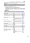
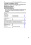
Parameters Set in Initial Setting Level . . . . . . . . . . . . . . . . . . . . . . . . . . . . . . . . . . . . . . . . .
95
B
Parameter Settings in the Adjustment Level . . . . . . . . . . . . . . . . . . . . . . . . . . . . . . . . . . . . .
97
Index. . . . . . . . . . . . . . . . . . . . . . . . . . . . . . . . . . . . . . . . . . . . .
99
Revision History . . . . . . . . . . . . . . . . . . . . . . . . . . . . . . . . . . . 103
xiv
About this Manual:
This manual describes the G3PW Power Controllers and includes the sections described below.
Please read this manual carefully and be sure you understand the information provided before
attempting to set up or operate a G3PW Power Controllers.
Section 1 provides an overview of the G3PW Power Controllers.
Section 2 provides the specifications of the G3PW Power Controllers and describes the part names
and functions.
Section 3 describes how to install and wire the G3PW Power Controllers.
Section 4 describes the control methods that you can use, the I/O configuration, and how to set
parameters for the G3PW Power Controllers.
Section 5 describes the functions you can use when operating the G3PW Power Controllers.
Section 6 provides information on using CompoWay/F communications.
Section 7 provides troubleshooting information.
The Appendices provide lists of the parameters in the initial setting level and the adjustment level.
!WARNING Failure to read and understand the information provided in this manual may result in personal injury or death, damage to the product, or product failure. Please read each section
in its entirety and be sure you understand the information provided in the section and
related sections before attempting any of the procedures or operations given.
xv
xvi
SECTION 1
Overview
This section provides an overview of the G3PW Power Controllers.
1-1
Overview of G3PW Power Controller . . . . . . . . . . . . . . . . . . . . . . . . . . . . . .
2
1-2
G3PW Features . . . . . . . . . . . . . . . . . . . . . . . . . . . . . . . . . . . . . . . . . . . . . . . .
3
1-2-1
Features of Constant-current and Standard Models . . . . . . . . . . . . .
3
1-2-2
Features of Constant-current Models Only. . . . . . . . . . . . . . . . . . . .
3
1-3
I/O Block Diagram . . . . . . . . . . . . . . . . . . . . . . . . . . . . . . . . . . . . . . . . . . . . .
5
1-4
Models and Specifications . . . . . . . . . . . . . . . . . . . . . . . . . . . . . . . . . . . . . . .
6
1
Section 1-1
Overview of G3PW Power Controller
1-1
Overview of G3PW Power Controller
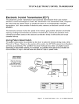
The G3PW Power Controller is a thyristor-type single-phase power controller
that enables precise temperature control. It accepts a continuous proportional
output of 4 to 20 mA or 1 to 5 V from a temperature controller to execute
phase control or optimum cycle control.
Measured
temperature
Temperature
controller
Input value (4 to 20 mA or 1 to 5 V)
Temperature sensor
Continuous proportional
current output (phase control
or optimum cycle control)
G3PW Power Controller
Heater
Just as with a solid state relay (SSR), ON/OFF control can be executed by
inputting a time-proportional output or ON/OFF output (i.e., voltage ON/OFF
signals) from a temperature controller.
Initial settings (output mode, input signal type, event input settings, etc.) and
adjustments (duty settings, soft-start up/down settings, etc.) can be made by
using keys on the front panel. The 7-segment display on the front panel can
also be used to monitor items such as the input value (%), output value (%),
phase angle (%), and load current (A) (see note).
Note
Constant-current Models only.
G3PW Power Controllers come in two models: Constant-current Models and
Standard Models. Constant-current Models provide current detection functions (constant current, current limit, overcurrent detection, and heater burnout detection) and serial communications (including connections to the EJ1
Modular Temperature Controller). Heater burnout detection is based on the
heater resistance rather than on the load current, making detection more
accurate.
2
Section 1-2
G3PW Features
1-2
1-2-1
G3PW Features
Features of Constant-current and Standard Models
Phase control or optimum cycle control can be selected by using either event
inputs or the keys on the front panel. Inrush current can be suppressed by
selecting phase control with the soft-start up/down functions at startup and
high-frequency noise can be suppressed by switching to optimum cycle control when in a steady state.
A Wide Selection of Output Modes Is Available for Phase Control
With phase control, any of the following modes can be selected for the input
signal or external setting: a mode with the output proportional to the phase
angle, a mode with the output proportional to the voltage, a mode with the output proportional to the square of the voltage (i.e., the power), or a mode with
the output proportional to the current (constant current mode, see note).
Note
Constant-current Models only.
Soft-start Up and Soft-start Down Functions
The soft-start up and soft-start down functions are used to change the output
value gradually within a set rate of change, even when the input value
changes suddenly. You can set the time for the output value to go from 0% to
100% or from 100% to 0% to 0.0 to 99.9 s.
Duty Setting
The duty setting is used to set the rate of change from 0% to 100% of the output value in relation to the input value.
Base-up Function
The base-up function increases the output value so that the output value does
not go to 0% even when the input value is 0%. This enables preheating the
heater even at an input value of 0%, which is effective when using a load for
which the heater temperature increases slowly.
Output Limit
The output limit is used to set upper and lower limits for the output value.
Instead of adjusting the rate of change of the output value in relation to the
input value, it enables upper and lower limits to be set on the current flowing
to the heater.
Total Run Time
Exceeded Detection
The total run time exceeded detection function outputs an alarm when the
total run time exceeds the preset Total Run Time Monitor value (kh). The total
run time can be monitored for notification of the need for replacement or preventive maintenance of the Power Controller or heater.
1-2-2
Features of Constant-current Models Only
Constant-current Control for Controlling a Pure Metal or Nonmetal Heater
Constant-current control measures the load current with a built-in CT, and
controls the load current so that it is proportional to the input. This stabilizes
the heating values of heaters (pure metal or nonmetal) for which the resistance changes due to temperature changes or deterioration over time.
Current Limit for the
Load Current
The current limit function measures the load current with a built-in CT and protects the heater by adjusting the phase angle to limit the load current so that a
preset load current limit is not exceeded. It is also used together with the softstart functions to limit the inrush current for pure-metal heaters and nonmetal
heaters.
3
Section 1-2
G3PW Features
Heater Burnout Detection and Alarm Based on Heater Resistance
This function detects changes in heater resistance. An alarm is output if a
change exceeds the set value. The Controller can be set to stop or hold the
output status when an alarm occurs.
With previous heater burnout detection functions, heater burnout was determined based on the rate of change of the electric current flowing to the heater.
The command value and the load current do not have a linear relationship, so
faulty detection can occur when the command value is changed. With the
G3PW Power Controllers, heater burnout is determined based on the rate of
change of the heater resistance, enabling more accurate heater burnout
detection when the command value changes.
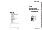
Serial Control from an EJ1 Modular Temperature Controller
Up to eight G3PW Power Controllers can be connected to a Basic Unit in an
EJ1 Modular Temperature Controller via RS-485. Using multiple Power Controllers enables a wire-saving temperature control system.
Measured
temperature
CX-Thermo
(Enables setting and
monitoring Power
Controller parameters.)
EJ1 Modular
Temperature
Controller
(Connected to End Unit.)
(Connected to Basic Unit.)
Input value
RS-485
Temperature sensors
G3PW Power Controllers
Heater
8 max.
Power Controller parameters can be set and monitored, and the control status
of items such as the load current can be monitored from CX-Thermo Support
Software running on a personal computer that is connected to the EJ1 End
Unit. For details, refer to the EJ1 Modular Temperature Controller User’s Manual (Cat. No. H142).
4
Section 1-3
I/O Block Diagram
1-3
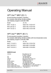
I/O Block Diagram
G3PW Power Controller
Control method
Input signal (4 to 20 mA, 1
to 5 V, or voltage ON/OFF
input (5 VDC/0 VDC))
Automatic
Phase control
or ON/OFF
Control
Manual
or
Optimum cycle
control
External main
setting (2 kΩ)
External duty
setting (2 kΩ)
Event input
(automatic/manual
setting or control method
selection)
External contacts
(alarm reset)
• Proportional to phase
angle (same as G3PX)
• Proportional to square
voltage
• Proportional to voltage
• Constant-current
control (See note.)
Heater
Built-in
CT
• Current limit (See note.)
• Heater burnout alarm
(See note.)
Alarm output 1
(contacts)
Alarm output 2
(contacts)
EJ1 Modular
Temperature
RS-485
Controller or
(See note.) CompoWay/F
Master
Note: Constant-current
Models only.
5
Section 1-4
Models and Specifications
1-4
Models and Specifications
G3PW-A2@@E@-@-@@@
1
2 3
Number
4
5 6
Item
7
8
Symbol
G3PW
A
Meaning of symbol
1
2
Basic model
Degree of protection
3
4
Voltage class
2
Maximum rated 20
current
45
60
200 VAC
20 A
5
Power supply
type
E
Single-phase power supply
6
Current control
U
C
Standard Model (no constant-current control)
Constant-current Model
7
Control terminal S
block
C
Terminal block with small slotted screws
Screwless clamp terminal block
8
RS-485 communications
Communications not supported.
Communications supported.
Blank
FLK
Power Controller
IP00
45 A
60 A
List of Models
Number of
phases
Control terminal block
Single-phase Terminal block
with small slotted screws
Type
Standard
Constant
current
Screwless clamp Standard
terminal block
Constant
current
Capacity
20 A
45 A
G3PW-A220EU-S
G3PW-A245EU-S
60 A
20 A
G3PW-A260EU-S
G3PW-A220EC-S-FLK
45 A
60 A
G3PW-A245EC-S-FLK
G3PW-A260EC-S-FLK
20 A
45 A
G3PW-A220EU-C
G3PW-A245EU-C
60 A
20 A
G3PW-A260EU-C
G3PW-A220EC-C-FLK
45 A
60 A
G3PW-A245EC-C-FLK
G3PW-A260EC-C-FLK
Optional Products
Name
Variable Resistor
6
Model number
Model
G32X-V2K (specified model)
SECTION 2
Specifications and Nomenclature
This section provides the specifications of the G3PW Power Controllers and describes the part names and functions.
2-1
Specifications . . . . . . . . . . . . . . . . . . . . . . . . . . . . . . . . . . . . . . . . . . . . . . . . .
8
2-2
Nomenclature and Operations. . . . . . . . . . . . . . . . . . . . . . . . . . . . . . . . . . . . .
14
7
Section 2-1
Specifications
2-1
Specifications
Specifications
Item
Standard Models
Model
Control method
Maximum load capacity
Output
mode
Analog input
Voltage ON/OFF
input
Phase
control
Optimum
cycle
control
Optimum cycle control (Output is switched to 100% or 0% each half
cycle.)
ON/OFF
control
Proportional to voltage control
Phase
Rated voltage
Single
100 to 240 VAC
Operating voltage range
Power supply frequency
−15% to +10%
50/60 Hz
Power supply frequency fluctuation
Load current
-A220E@
±3 Hz
1 to 20 A
Inrush current
resistance
Constant-current Models
G3PW-A2@@EU-@
G3PW-A2@@EC-@-FLK
Analog input: Phase control or optimum cycle control
Voltage ON/OFF input: ON/OFF control
• Phase control: Linear (resistive) load, transformer primary-side control
(Magnetic flux density: 1.25 T max.)
• Optimum cycle control: Linear (resistive) load (Transformer primary-side
control is not supported.)
Proportional to phase angle (same Proportional to phase angle (same
as G3PX), proportional to square
as G3PX), proportional to square
voltage, proportional to voltage
voltage, proportional to voltage, constant-current control
-A245E@
-A260E@
1 to 45 A
1 to 60 A
-A220E@
-A245E@
220 A (60 Hz, 1 cycle)
440 A (60 Hz, 1 cycle)
-A260E@
Output voltage adjustable range
440 A (60 Hz, 1 cycle)
0% to 98%
Input signal for
control
Analog input
4 to 20 mA DC (input impedance: 100 Ω) or 1 to 5 VDC (input impedance:
30.1 kΩ)
Voltage ON/OFF Input
External main setting
5 VDC (input impedance: 30.1 kΩ)
Specified Variable Resistor: G32X-V2K (2 kΩ, 2 W)
External duty setting
Main setting
0.0 to 100%
Output value
setting range
Base-up value
Upper/ lower limits
Duty setting
0.0 to 100% (Default: 0.0%)
Output upper limit: 0.0% to 100% (Default: 100%)
Output lower limit: 0.0% to 100% (Default: 0.0%)
Duty setting = Internal duty setting x External duty setting
Internal duty setting range (set using front-panel keys or communications): 0% to 100% (Default: 100%)
External duty setting range (set using external variable resistor): 0% to
100% (Default: 100%)
Soft-start up time and soft-start down time
0.0 to 99.9 s (Default: 0.5 s)
Either phase control or optimum cycle control can be used.
Constant current
Load current upper limit
-----
8
Current fluctuation: ±2% FS
0.0 to 66.0 (Default: 0.0 = OFF)
Overcurrent detection time: 500 ms
max.
Section 2-1
Specifications
Item
Standard Models
G3PW-A2@@EU-@
Model
Current detection
Heater burnout
alarm
Constant-current Models
G3PW-A2@@EC-@-FLK
Current transformer
(CT)
Current detection
accuracy
Minimum detected load
current
Burnout detection
accuracy
---
Built-in
---
10% FS of rated current
---
1A
---
Detection method
---
10% FS at rated current
(Not applicable to loads with variable
resistance.)
According to heater resistance (with
heater resistance teaching and
Heater Burnout Threshold parameter)
Setting range for heater --burnout detection
Burnout detection
output lower limit
---
Number of alarms for
--heater burnout
detection
Multiple heater burnout --detections
Note The accuracy of heater burnout detection will be lower for
heaters for which the resistance significantly changes
depending on the temperature.
1% to 100% (Default: 100%)
Detects a burnout at or above the
specified output value.
0.0% to 100% (Default: 0.0%)
0 to 999 (Default: 150)
Burnout of 1 of 10 heater elements
can be detected (at the rated current).
Event inputs
Number of event inputs 2 event inputs
Event input 1: The function of the event input can be changed with a
parameter setting in the initial setting level. The event input
can be used for one of the following functions.
• Switching the main setting between automatic and manual operation.
• Switching between phase control and optimum cycle
control.
Event input 2: Alarm reset
Contact input
ON: 1 kΩ max., OFF: 100 kΩ min.
conditions
Non-contact input
ON residual voltage: 1.0 V min., OFF leakage current: 0.1 mA max.
conditions
Current flow
Approx. 1.1 mA (per input)
Alarm outputs
Number of alarm
outputs
Maximum operating
voltage
Maximum load current
Maximum residual
voltage
Maximum leakage
current
2 alarm outputs
Alarm output 1: ALARM1 (caution)
Alarm output 2: ALARM2 (warning)
Open-collector outputs
30 VDC
50 mA
1.5 V
0.4 mA
9
Section 2-1
Specifications
Item
Standard Models
G3PW-A2@@EU-@
Model
Serial communications
---
Constant-current Models
G3PW-A2@@EC-@-FLK
One RS-485 port: CompoWay/F
slave function (See note.)
Note Connection is possible to a
Basic Unit in an EJ1 Modular
Temperature Controller.
Parameters can be set and
monitored from the CXThermo Support Software
running on a computer that is
connected to the EJ1 End
Unit.
Rated current × 120% min., within
250 cycles
Overcurrent detection
---
SSR failure detection
Power supply frequency error
An error is detected within 3 seconds after an SSR failure.
• Phase angle range for SSR short-circuit failure detection: 0% to 72%
• Phase angle range for SSR open failure detection: 28% to 100%
Not within 47 to 63 Hz
Leakage current
Insulation resistance
10 mA max. (100/110 VAC), 20 mA max. (200/220 VAC)
100 MΩ min. (at 500 VDC)
Dielectric strength
2,500 VAC at 50/60 Hz for 1 min between charged parts and non-charged
parts
Vibration resistance
10 to 55 to 10 Hz, 100 m/s2
Shock resistance
300 m/s2
Ambient operating temperature
Ambient operating humidity
−15°C to + 55°C (with no icing or condensation)
5% to 95%
Storage temperature
Fuses (fuses recommended for external
connection)
Fast-acting fuses
−25°C to + 65°C (with no icing or condensation)
Time-delay fuses
Weight
10
Super-rapid Fuse (Fuji Electric)
For 20 A, CR6L-20/UL
Fuse Holder
(Fuji Electric)
CMS-4
For 45 A, CR6L-50/UL
For 60 A, CR6L-75/UL
CMS-5
250 VAC, 2 A
G3PW-A220E@-@-@@@: 1.0 kg max.
G3PW-A245E@-@-@@@: 1.9 kg max.
G3PW-A260E@-@-@@@: 1.9 kg max.
Section 2-1
Specifications
Serial Communications Specifications (Constant-current Models Only)
Item
Communications
protocol
Constant-current Models (G3PW-A2@@EC-@-FLK)
CompoWay/F Slave
Communications
functions
Reading and writing all parameters
Transmission path
connections
Multipoint
Communications
method
Maximum
transmission
distance
RS-485
Number of
nodes
Sync method
31 (Multi-drop connections)
Baud rate
Transmission code
9.6, 19.2, 38.4 or 57.6 kbit/s (Default: 57.6 kbit/s)
ASCII
Data length
Stop bits
7 or 8 bits (Default: 7 bits)
1 or 2 bits (Default: 2 bits)
Parity
Flow control
Vertical parity (None, even, odd) (Default: Even)
None
500 m
Start-stop synchronization
11
Section 2-1
Specifications
Comparison with Previous Model (G3PX)
G3PX
Simple
models
Model
EUN
EH
Number of heater phases
Single-phase
Control object
Alloy (nichrome)
Load voltage
200 V
100/110/200/220 VAC
400 V
---
Load current
Control method
G3PW
Advanced
Simple
models
EHN
EC
Advanced
DU
DH
1 to 20, 1 to 40, or 1 to 60 A
Constantcurrent
EU
EC
DC
3-phase
Pure
metal
(Kanthal
Super)
Standard
Single-phase
Alloy (nichrome)
Pure
metal
(Kanthal
Super)
Alloy
Pure
(nichrome) metal
(Kanthal
Super)
200/220 VAC
100 to 240 VAC
1 to 20 or 1 to 60 A
1 to 20, 1 to 45, or 1 to
60 A
Phase Control
Supported Supported Supported Supported Supported Supported Supported Supported Supported
Optimum cycle control
---
Proportional to phase
angle control
Supported Supported Supported Supported Supported Supported Supported Supported Supported
Proportional to voltage control
---
---
---
---
---
---
---
Supported Supported
Proportional to square
voltage control
---
---
---
---
---
---
---
Supported Supported
Constant-current control (proportional to
current)
---
---
---
Supported ---
---
Supported ---
Analog input (continuous proportional)
Supported
Supported Supported
Voltage ON/OFF input
(time-proportional)
Supported
Supported Supported
(5 V/0 V
(5 V/0 V
input)
input)
External main setting
(using external variable resistor)
Supported
Supported Supported
Serial communications (RS-485)
---
---
Supported
Selecting automatic or manual for the
main setting
Switched by changing connections.
Event
input, key
operation
Event
input, key
operation,
communications
Duty settings
Internal setting
Supported Supported Supported Supported Supported Supported Supported Supported
(Keys)
External setting
Supported Supported Supported Supported Supported Supported Supported Supported Supported
Displayed on 7-segment display
---
Level indicators (output display)
Supported Supported Supported Supported Supported Supported Supported ---
Soft-start function
---
Long soft-start up/
down
Supported ---
Supported Supported Supported Supported Supported
Soft-start down function
Supported*
Supported*
Supported*
Supported*
Base-up function
Supported ---
---
---
Supported Supported ---
Load current limit
---
---
---
Supported ---
---
Supported ---
Output upper/lower
limits
---
---
---
---
---
---
---
Supported Supported
Total run time
exceeded detection
---
---
---
---
---
---
---
Supported Supported
Event inputs
1 (alarm reset)
Alarm outputs
1
1
1
1
1
1
1
2 (warning, caution)
Serial communications (RS-485)
---
---
---
---
---
---
---
---
Output mode
Input signals
from host
Functions
I/O functions
12
---
---
---
---
Supported ---
Supported*
---
---
---
---
---
---
---
---
---
Supported*
---
---
---
Supported*
Supported Supported
Supported
Supported
(Keys or
communications)
Supported Supported
---
Supported Supported
Supported Supported
Supported Supported
Supported
2 (alarm reset) (automatic/manual selection
or control method
selection)
Supported
Section 2-1
Specifications
G3PX
Simple
models
Model
Error monitoring
Advanced
EUN
EH
Overcurrent detection
---
---
Single heater burnout
detection
---
Multiple heater burnout detection
---
EHN
---
G3PW
Simple
models
EC
Advanced
DU
DH
DC
EU
EC
Supported
Supported Supported Supported ---
Supported Supported ---
Supported
---
---
---
---
---
Supported (1
element
out of 10)
SSR short-circuit (ele- --ment ON failure detection)
Supported Supported Supported ---
---
---
Supported Supported
SSR open failure
---
---
---
---
---
---
---
Supported Supported
CT Failure
---
---
---
---
---
---
---
---
Zero cross error
---
---
---
---
---
---
---
Supported Supported
External input range
error (external input
disconnection detection)
---
---
---
---
---
---
---
Supported Supported
Power supply frequency error
---
---
---
---
---
---
---
Supported Supported
---
---
Constantcurrent
Supported ---
Supported (1
element
out of 5)
Supported ---
Standard
Supported
* The soft-start down time is the same as the soft-start up time.
13
Section 2-2
Nomenclature and Operations
2-2
Nomenclature and Operations
Nomenclature
A model with a terminal block with small slotted screws is shown as an example.
Level indicators
7-segment display
Monitoring
indicators
Communications
indicator
Control terminal
block
Protective cover
(removable)
Reset/event indicator
LVL Key
UP Key
DOWN Key
ENT/RST Key
Command input and
power supply terminal
block (with cover)
1. 1 to 5-V/0 or 5-V input
2. 4 to 20-mA input
3. Current/voltage input COM
4. 100 to 240 VAC
5. 100 to 240 VAC
Load terminal block
(under protective cover)
100 to 240 VAC
Indicators
Level Indicators
Indicator
ADJ
Description
Lit when in the adjustment level.
SET
Lit when in the initial setting level.
EV
Lit when an external contact reset input or an event input is ON.
Indicator
%(IN)
Description
Lit when the input value is monitored in the monitor level.
%(DUTY)
Lit when the duty value is monitored in the monitor level.
%(OUT)
Lit when the output value is monitored in the monitor level.
%(PHASE)
Lit when the phase angle is monitored in the monitor level.
A
Lit when the current is monitored in the monitor level.
Indicator
Description
Lit when the serial communications are in progress.
Monitoring Indicators
Communications Indicator
COMM
14
Section 2-2
Nomenclature and Operations
Operation Keys
Key symbol
Name
LVL (Level) Key
Description
Level Changes
• Monitor level ↔ Adjustment level
• Monitor level ↔ Initial setting level
• Software is reset when moving from
the initial setting level to monitor
level.
Enabling condition
Changing from monitor level to adjustment level or from monitor level to initial setting level is possible even when
an error occurs.
ENT/RST (Enter/
Reset) Key
Set value display
Set value change and entry
Error reset
UP Key
Set value change
Monitor item/set value number change
In the monitor level, the ENT/RST Key
functions as a Reset Key only when an
error occurs. (It does not function as a
Reset Key when there is no error.)
---
LVL
ENT
RST
DOWN Key
Command Input and Power Supply Terminal Block
1
2
3
4
N
5
L
1. 1 to 5-V input
2. 4 to 20 mA input
3. Current/voltage input COM
4. 100 to 240 VAC
5. 100 to 240 VAC
Load Terminal Block (Under Protective Cover)
T1
L1
Load circuit output terminal (T1)
Load circuit output terminal (L1)
15
Section 2-2
Nomenclature and Operations
Control Terminal Block
■ Screwless
Clamp Terminal Block
■ Terminal
Block with Small Slotted
Screws
1. RS-485 (+)
1. RS-485 (+)
2. RS-485 (−)
2. RS-485 (−)
3. Main setting
3. Main setting
4. Main setting COM
4. Main setting COM
5. Duty setting
5. Duty setting
6. Duty setting COM
6. Duty setting COM
7. Alarm output 1 (+)
7. Alarm output 1 (+)
8. Alarm output 1 (−)
8. Alarm output 1 (−)
9. Alarm output 2 (+)
9. Alarm output 2 (+)
10. Alarm output 2 (−)
10. Alarm output 2 (−)
11. Event input (+)
11. Event input (+)
12. Event input (−)
12. Event input (−)
13. Reset input (+)
13. Reset input (+)
14. Reset input (−)
14. Reset input (−)
For standard models, 1 and 2 are not used.
Pin No.
16
Name
1
RS-485 (+)
2
3
RS-485 (−)
Main setting
4
5
Main setting COM
Duty setting
6
7
Duty setting COM
Alarm output 1 (+)
8
9
Alarm output 1 (−)
Alarm output 2 (+)
10
11
Alarm output 2 (−)
Event input (+)
12
Event input (−)
13
Reset input (+)
14
Reset input (−)
For standard models, 1 and 2 are not used.
Description of function
RS-485 communications
Terminals for connecting external variable
resistor for main setting
Terminals for connecting external variable
resistor for duty setting
Alarm output for fatal errors. The output to
the load is stopped.
Alarm output non-fatal errors. The output
to the load is not stopped.
Terminals for connecting event inputs. The
functions for event inputs are selected with
parameter settings in the initial setting
level using the Event Input Assignment
parameter [P11].
The reset input is valid only for alarm level
2 (alarm output 2).
SECTION 3
Installation and Wiring
The section describes how to install and wire the G3PW Power Controllers.
3-1
Installation Environment . . . . . . . . . . . . . . . . . . . . . . . . . . . . . . . . . . . . . . . . .
18
3-2
Installation. . . . . . . . . . . . . . . . . . . . . . . . . . . . . . . . . . . . . . . . . . . . . . . . . . . .
21
3-3
Wiring . . . . . . . . . . . . . . . . . . . . . . . . . . . . . . . . . . . . . . . . . . . . . . . . . . . . . . .
26
3-3-1
Wiring the Power Supply and Load Circuits . . . . . . . . . . . . . . . . . .
26
3-3-2
Command Input and Power Supply Terminal Wiring . . . . . . . . . . .
27
3-3-3
Wiring the Control Terminal Block . . . . . . . . . . . . . . . . . . . . . . . . .
28
3-3-4
Grounding . . . . . . . . . . . . . . . . . . . . . . . . . . . . . . . . . . . . . . . . . . . . .
31
3-3-5
Wiring an External Noise Filter . . . . . . . . . . . . . . . . . . . . . . . . . . . .
31
Wiring for Specific Applications . . . . . . . . . . . . . . . . . . . . . . . . . . . . . . . . . .
32
3-4
17
Section 3-1
Installation Environment
3-1
Installation Environment
Installation Environment
Use and store the Power Controller within the rated ambient temperature and
humidity ranges. If more them one Power Controller is installed side-by-side
or vertically, the heat that is generated will cause the internal temperatures of
the Power Controllers to rise and will shorten their service life. In these kinds
of installations, take suitable measures, such as installing fans for forced cooling.
The Power Controller is designed for indoor use only. Also, do not use the
Power Controller in the following environments.
• Locations subject to water or oil
• Locations subject to direct sunlight
• Locations where dust or corrosive gases (in particular, sulfuric or ammonia gas) are present
• Locations where flammable or explosive gases are present
• Locations subject to extreme temperature changes
• Locations where icing or condensation may occur
• Locations subject to excessive shocks or vibration
• Locations subject to direct heat radiated from heating devices.
Take appropriate and sufficient countermeasures when installing systems in
the following locations:
• Locations subject to static electricity or other forms of noise.
• Locations subject to strong electromagnetic fields.
• Locations subject to possible exposure to radioactivity.
• Locations close to power supplies.
Installation Location
When installing in a control panel, consider the ease of operation, ease of
maintenance, and environmental factors.
!WARNING Leave at least 100 mm of space above and below the Power Controller when
installing it to allow heat to dissipate. Do not obstruct the area around the
Power Controller and especially the area around the heat sink.
The ambient operating temperature range is −15 to 55°C, but take the following considerations into account. When the ambient temperature exceeds
40°C, reduce the maximum load current as shown below.
Ambient Temperature
■
Current and Temperature Characteristics (G3PW-A220E/A245E)
Load current (%)
100
80
60
40
20
0
10
20
30
40
50 55 60
Ambient temperature (°C)
18
Section 3-1
Installation Environment
■
Current-temperature Characteristic (G3PW-A260E)
Load current (%)
100
A
80
B
60
40
A: Installation with 20 mm
between Power Controllers
B: Close mounting
20
0
10
20 30 40 50 55 60
Ambient temperature (°C)
• At least 20 mm must be provided on the left and right sides of the G3PWA260E. Refer to 3-2 Installation. If you must use side-by-side mounting,
then reduce the maximum load current when the ambient temperature is
over 30°C.
• Certification for safety standards was obtained with a mounting interval of
20 mm.
• Leave sufficient space for ventilation.
• Do not install the Power Controller above devices that generate significant
amounts of heat, such as heaters, transformers, and high-capacity resistors.
• If the ambient temperature reaches 55°C or higher, install an air conditioner to lower the temperature.
Note
If more than one Power Controller is installed side-by-side or vertically, the
heat that is generated will cause the internal temperatures of the Power Controllers to rise and will shorten their service life. Take suitable measures, such
as installing fans for forced-air cooling.
Improving Noise
Immunity
• Do not install the Power Controller in a control panel together with highvoltage devices.
• Install the Power Controller at least 200 mm away from power lines.
■
Recommended External Noise Filter
We recommend installing a noise filter on the primary side to improve noise
immunity.
Recommended filter: RSMN-series Filters from TDK-Lambda Corporation
RSMN-2030: For 20 A
RSMN-2060: For 45/60 A
Refer to 3-3-5 Wiring an External Noise Filter for wiring methods.
19
Section 3-1
Installation Environment
Resistance to Inrush Current
The solid lines in the following graphs show the non-repetitive resistance to
inrush current. For repetitive inrush current, keep the inrush current below the
values shown by the dotted lines.
G3PW-A220E@
Inrush current (A. peak)
■
200
150
100
50
0
10
100 200
500 1,000
5,000
Power ON time (ms)
G3PW-A245E@/A260E@
Inrush current (A. peak)
■
30 50
400
300
200
100
0
10
20
30 50 100 200
500 1,000
5,000
Power ON time (ms)
Section 3-2
Installation
3-2
Installation
Installation Direction
For cooling efficiency, install the Power Controller in the correct direction. The
Power Controller generates a lot of heat, and it uses natural heat convection
for cooling. Installing the Power Controller in the wrong direction may cause it
to malfunction or to be damaged.
!WARNING Install the Power Controller in the direction shown in this manual. The Power
Controller generates a lot of heat and it uses natural heat convection for cooling. Installing the Power Controller in the wrong direction may cause in malfunctions or accidents.
!WARNING Leave at least 100 mm of space above and below the Power Controller when
installing it to allow heat to dissipate.
Do not obstruct the area around the Power Controller and especially the area
around the heat sink.
Top
Natural
convection
Bottom
Other devices
Other devices
100 mm min.
Airflow
Mounting surface
Specified distance or longer
Other devices
100 mm min.
Other devices
21
Section 3-2
Installation
External Dimensions and Mounting Hole Dimensions
G3PW-A220E@-S (20-A Models with Terminal Block with Small Slotted Screws)
136.5
120
40
146.4
170
50
G3PW-A220E@-C (20-A Models with Screwless Clamp Terminal Block)
137
120
40
146.4
170
50
G3PW-A245E@-S/A260E@-S (45/60-A Models with Terminal Block with Small Slotted Screws)
154.5
138
22
104
171.5
188
70
Section 3-2
Installation
G3PW-A245E@-C/A260E@-C (45/60-A Models with Screwless Clamp Terminal Block)
155
138
70
171.5
188
104
Mounting Hole Dimensions
■
G3PW-A245
100 min.
G3PW-A220
176±0.2
158±0.2
100 min.
■
Two, M5
Two, M5
38±0.2
51 min.
57.6±0.2
71 min.
23
Section 3-2
Installation
G3PW-A260
176±0.2
100 min.
■
Two, M5
57.6±0.2
90 min.
Mounting Screws
Model
All models
Tightening torque
2.3 to 2.5 N·m
Screw size
M5, length: 10 mm min.
Control Panel Ventilation
The G3PW Power Controller generates a lot of heat and it uses natural heat
convection for cooling. Mounting the Power Controller in the wrong direction
may obstruct heat radiation and cause malfunctions or accidents. To increase
cooling efficiency, mount the Power Controller in the correct direction and take
control panel ventilation and the installation location into consideration to
avoid obstructing heat dissipation.
24
Section 3-2
Installation
Mounting Position in Relation to Wiring Duct
155 mm min.
Wiring duct
Wiring duct
Other devices
Mounting surface
Airflow
Airflow
Other devices
Wiring duct
Wiring duct
If a device with a depth of 155 mm or
more blocks the top or bottom of the Power Controller, the flow of air will be obstructed and heat will not dissipate.
Control Panel Ventilation
Airflow
Mounting
base
Use short wiring ducts or other devices around the Power Controller
If tall devices or wiring ducts must be used,
take measures such as mounting the Power
Controller to a mounting base to improve
ventilation.
When mounting the Power Controller in a control panel, consider measures
such as installing louvers or fans for ventilation in the control panel.
• If the air intake and outlet ports have filters, perform periodic maintenance
to prevent the filters from becoming clogged.
• Install devices in such a way that airflow is not blocked inside or outside of
the air intake and outlet ports.
• If using a heat exchanger for cooling inside the panel, it is most effective
to mount it on the front of the Power Controller.
Control panel
Wiring duct
Louver, axialflow ventilation
fan, etc.
G3PW
Louver
Wiring duct
25
Section 3-3
Wiring
3-3
3-3-1
Wiring
Wiring the Power Supply and Load Circuits
• First, connect the load to load terminal T1 and to the power supply, and
then connect the power supply to load terminal L1 through a fast-acting
fuse.
• Connect the AC power supply to power supply terminals 4 (N) and 5 (L).
• The AC power supply ground polarity and the G3PW terminal block polarity are not related, but connect the 4 (N) and 5 (L) terminals on the command input/power supply terminal block and the T1 and L1 terminals of
the load terminal block to power supplies with the same phases.
• Always connect the load to load terminal T1.
1
2
3
T1
N
4
L1
Time-delay
fuse
Power supply
100 to 240 VAC
(50/60 Hz)
L
5
Command
input/power
supply
terminal block
Load
terminal block
Load
Load circuit (T1)
Fast-acting fuse
Load circuit (L1)
!WARNING Make sure that the phases match for load terminal T1 and power supply terminal 4 (N), and for load terminal L1 and power supply terminal 5 (L). If the
connections are incorrect, the Power Controller will not operate normally or
the load may be damaged.
!Caution When connecting from line connected to load terminal T1 to power supply terminal 4 (N), connect it from a point that is as close as possible to the power
supply. If the connection is incorrect, the output operation will be stopped by
the Power Controller failure detection functions.
!Caution When using the Power Controller to control the power to the primary side of a
transformer, do not open the circuit on the secondary side of the transformer
during Power Controller operation.
Wiring the Load Terminal Block
Recommended Wires
When connecting to the load terminals, use the specified wire size for each
model of Power Controller.
Model
G3PW-A220
G3PW-A245
G3PW-A260
Note
26
Recommended
wire size
AWG 10 to 18
AWG 6
(See note.)
Tightening torque
1.8 N·m
2.8 N·m
Terminal screws
M4
M5
Crimp terminals that conform to UL and CSA specifications must
be used.
Section 3-3
Wiring
!Caution Be sure to keep terminal screws tightened to the torque specified below.
Loose screws may occasionally cause a fire.
Recommended Crimp
Terminals
• Either use insulated crimp terminals or cover the crimp terminals with
insulating sleeves.
• Always use the following crimp terminals to wire the load terminals.
• Do not connect more than two crimp terminals to one terminal screw.
Model
A
A
G3PW-A220
G3PW-A245/A260
9.5 mm max.
12 mm max.
Recommended Fuses
Fast-acting fuse
Time-delay fuses
3-3-2
Super-rapid Fuse (Fuji Electric)
Fuse Holder (Fuji
Electric)
For 20 A
For 45 A
CR6L-20/UL
CR6L-50/UL
CMS-4
For 60 A
250 VAC, 2 A
CR6L-75/UL
CMS-5
Command Input and Power Supply Terminal Wiring
Command Input and Power Supply Terminal Wiring
Voltage Input (1 to 5 VDC)
When using a voltage input, connect the positive and negative signal wires to
terminals 1 and 3, respectively.
1
Temperature
controller or
other controller
Current Input (4 to 20 mA
DC)
3
4
5
+
−
1 to 5-V output
When using current input, connect the positive and negative signal wires to
terminals 2 and 3, respectively.
1
Temperature
controller or
other controller
ON/OFF Voltage Input (0
or 5 VDC)
2
2
3
4
5
+
−
4 to 20-mA output
When using an ON/OFF voltage input, connect the positive and negative signal wires to terminals 1 and 3, respectively.
1
2
3
4
5
0 or 5-V output
+
PLC or other
controller
−
27
Section 3-3
Wiring
The G3PW may be damaged if a command voltage that is higher than 5 V is
applied. If it is necessary to apply more than 5 V, split the voltage as shown
below by inserting resistance in the line to terminal 1 and applying the voltage
across terminals 1 and 3. The internal impedance between terminals 1 and 3
is 30.1 kΩ.
Internal impedance: 30.1 kΩ
1
Output of 5 V
or higher
PLC or
other
controller
+
2
3
N
L
Resistance
Output
voltage
Resistance
0 or 5 V
0 or 12 V
Not required
42 kΩ, 1/5 W min.
0 or 24 V
120 kΩ, 1/5 W min.
−
Command Input and Power Supply Wire Sizes
Model
Recommended wire
diameter
All models
AWG 14 to 18
Tightening torque
0.8 to 1.0 N·m
Terminal screws
M3.5
Recommended Crimp Terminals
Always use the following crimp terminals (for M3.5) to wire to the command
input and power supply terminals.
7.2 mm max.
7.2 mm max.
3-3-3
Wiring the Control Terminal Block
Recommended Wire Sizes and Connection Method
• G3PW-A2@@E@-S (Models with terminal blocks with small slotted
screws)
• G3PW-A2@@E@-C (Models with screwless clamp terminal block)
• Wire Sizes for Control Terminals (Models with Small Slotted or Screwless
Clamp Terminals)
Model
All models
Note
Recommended
wire diameter
AWG26 to AWG16
Tightening torque
0.22 N·m
Terminal screws
(See note.)
M2
Only models with terminal blocks with small slotted screws have
terminal screws.
• Use copper AWG26 to AWG16 twisted-pair cable when connecting the
wires directly.
• Strip the wire sheathing for the following lengths, according to the connector type.
• Small slotted terminals: 7 mm
• Screwless clamp terminals: 9 mm
• When using twisted wires, it is recommended that you attach a ferrule
with an insulating cover that conforms to DIN 46228-4 and connect the
ferrule to the terminal.
28
Section 3-3
Wiring
• Use shielded twisted-pair wires for RS-485 communications wires. A
maximum of 500 m total of wiring can be used.
Terminal Names
A screwless clamp terminal block is shown as an example.
+
Multi-drop (See note.)
Max. of 31 nodes
−
EJ1 Modular Temperature
Controller, CJ-series Serial
Communications Unit, etc.
1. RS-485 (+)
+
2. RS-485 (−)
3. Main setting
−
4. Main setting COM
5. Duty setting
6. Duty setting COM
Load
7. Alarm output 1 (+)
8. Alarm output 1 (−)
Automatic
Load
9. Alarm output 2 (+)
10. Alarm output 2 (−)
11. Event input (+)
Manual
12. Event input (−)
13. Reset input (+)
14. Reset input (−)
For standard models, 1 and 2
are not used.
Note
Wiring Inputs for External
Settings
■
A terminator must be connected at each end of the RS-485 transmission path. The terminators must be at least 54 Ω combined.
Wiring to Adjust the Main
Setting
Use a G32X-V2K
Variable Resistor
to adjust the main
setting.
1
2
■
Wiring to Adjust the Duty Setting
Use a G32X-V2K
Variable Resistor to
adjust the duty setting.
1
3. Main setting
4. Main setting
COM
2
5. Duty setting
3
3
6. Duty setting COM
Alarm Outputs
Load
Load
1
2
3
4
5
6
7. Alarm output 1 (+)
8. Alarm output 1 (−)
9. Alarm output 2 (+)
10. Alarm output 2 (−)
11
12
13
14
Output status
Number of outputs
Open collector
2
Maximum operating voltage
30 VDC
Maximum load
current
50 mA
Maximum residual voltage
Maximum leakage current
1.5 V
0.4 mA
29
Section 3-3
Wiring
1,2,3...
1. When alarm output 1 or alarm output 2 is reset (i.e., the power turns ON or
the initial setting level is exited), the alarm output will be inactive for 1 second. Allow for this in the system design when using an alarm output.
G3PW Power
Controller
AC power supply
ALARM 1/2
Operation for NO
Contacts
Alarm output
inactive period
ALARM 1/2
Operation for NC
contacts
1 s max.
Alarm
Power ON
2. If you connect a contact relay or any device containing a coil to the alarm
output, wire a diode in parallel with the relay coil, as shown in the figure.
X
7. Alarm output 1 (+)
8. Alarm output 1 (−)
9. Alarm output 2 (+)
10. Alarm output 2 (−)
X
■
Automatic
Manual
Reset Input
1
2
3
4
5
6
7
8
9
10
11. Event input (+)
12. Event input (−)
13
14
1
2
3
4
5
6
7
8
9
10
11
12
13. Reset input (+)
14. Reset input (−)
Number of event inputs
2 event inputs
Contact input conditions
ON: 1 kΩ max.
OFF: 100 kΩ min.
Non-contact input conditions
ON residual voltage: 1.0 V min.
OFF leakage current: 0.1 mA max.
Approx. 1.1 mA (per input)
Current flow
30
■
Operation Selection Input
Section 3-3
Wiring
■
Communications Terminals
+
−
Multi-drop
Max. of 31 nodes
1. RS-485(+)
2. RS-485(−)
3
4
5
6
7
8
9
10
11
12
13
14
For standard models, 1 and 2 are not used.
EJ1 Modular Temperature Controller, CJ-series Serial Communications Unit, etc.
• The terminating resistance is 54 Ω min. combined.
• Both ends of the transmission path (including the host computer if it is at
one end), must be specified as end nodes (terminating resistance). Use a
combined terminating resistance of at least 54 Ω.
• The EJ1 has an internal terminating resistance of 120 Ω. Install terminating resistance (110 to 125 Ω, 1/2 W) at only the end G3PW Power Controller.
3-3-4
Grounding
Always ground the Power Controller to 100 Ω or less. There are no ground terminals provided, so use the heat sink mounting screws as ground terminals.
3-3-5
Wiring an External Noise Filter
Always insert a noise filter in the power supply lines to the G3PW.
1
2
T1
Time-delay fuse
Noise Filter
RSMN-2030/2060
(TDK-Lambda Corporation)
Power supply
100 to 240 VAC
(50/60 Hz)
1
2
3
4
Load
N
4
3
L
5
Command
input/power
supply
terminal block
L1
Load
terminal block
Load circuit (T1)
Load circuit (L1)
Fast-acting fuse
31
Section 3-4
Wiring for Specific Applications
3-4
Wiring for Specific Applications
Automatic Operation
Wiring Example for Automatic Operation Using Current Signal Input of 4 to 20 mA
1
2
3
4
5
+
Temperature
controller or
other controller
−
4 to 20-mA output
Wiring Example for Automatic Operation Using Voltage Signal Input of 1 to 5 V
1
Temperature
controller or
other controller
2
3
4
5
+
−
1 to 5-V output
Wiring Example for Automatic Operation Based on RS-485 Communications
+
−
EJ1 Modular Temperature
Controller, CJ-series Serial
Communications Unit, etc.
Multi-drop (See note.)
Max. of 31 nodes
1. RS-485 (+)
+
2. RS-485 (−)
3. Main setting
−
4. Main setting COM
5. Duty setting
6. Duty setting COM
Load
7. Alarm output 1 (+)
8. Alarm output 1 (−)
Automatic
Load
9. Alarm output 2 (+)
10. Alarm output 2 (−)
11. Event input (+)
Manual
12. Event input (−)
13. Reset input (+)
14. Reset input (−)
For standard models, 1 and 2
are not used.
Note
32
A terminator must be connected at each end of the RS-485 transmission path. The terminators must be at least 54 Ω combined.
Section 3-4
Wiring for Specific Applications
Manual Operation
Wiring Example for Using an External Variable Resistor for the Main Setting
Use a G32X-V2K
Variable Resistor to
adjust the main
setting.
1
3. Main setting
4. Main setting COM
2
3
Wiring Example for Using an External Variable Resistor for the Duty Setting
Use a G32X-V2K
Variable Resistor to
adjust the duty
setting.
1
5. Duty setting
2
6. Duty setting COM
3
33
Wiring for Specific Applications
34
Section 3-4
SECTION 4
Control Methods and I/O Configuration
This section describes the control methods that you can use, the I/O configuration, and how to set parameters for the G3PW
Power Controllers.
4-1
Control Methods . . . . . . . . . . . . . . . . . . . . . . . . . . . . . . . . . . . . . . . . . . . . . . .
36
4-2
Output Modes . . . . . . . . . . . . . . . . . . . . . . . . . . . . . . . . . . . . . . . . . . . . . . . . .
37
4-3
Monitored Items . . . . . . . . . . . . . . . . . . . . . . . . . . . . . . . . . . . . . . . . . . . . . . .
38
4-4
Input System . . . . . . . . . . . . . . . . . . . . . . . . . . . . . . . . . . . . . . . . . . . . . . . . . .
39
4-5
Procedures for Operation and Setting Parameters . . . . . . . . . . . . . . . . . . . . .
40
4-6
Setting Parameters in the Initial Setting Level . . . . . . . . . . . . . . . . . . . . . . . .
43
35
Section 4-1
Control Methods
4-1
Control Methods
Any of the following methods can be used as the output mode for the G3PW
Power Controller: Phase control, optimum cycle control, or ON/OFF control. In
addition, it is possible to switch between phase control and optimum cycle
control during operation.
Phase Control
With phase control, the phase-angle range for the AC voltage supplied to the
load is changed by the switching element to continually change the power
supplied to the load.
Phase control is suitable for precise temperature control or for controlling
heaters with large inrush currents.
OFF ON
Optimum Cycle
Control
With optimum cycle control, the output is turned ON and OFF with each AC
half cycle. The output is switched at the voltage zero-cross point, enabling
high-precision temperature control while suppressing noise.
ON/OFF Control
With ON/OFF control, the control output is switched ON and OFF based on
the ON/OFF voltage signal from the temperature controller. The output phase
angle is set using operation keys or an external variable resistor.
Output OFF
36
Output ON
Output OFF
Output ON
Section 4-2
Output Modes
Output Modes
When phase control is used as the control method, any of the following four
modes can be selected for the relationship of the control value to the output
value.
In this mode, the relationship of the output phase
angle to the output value
has the same characteristics
as for the G3PX Power Controller.
Control Proportional to Phase Angle
(Same as G3PX)
100
Phase angle (%)
Control proportional to
phase angle
(same as
G3PX)
80
60
40
20
0
0
20
40
60
80
100
Output value (%)
In this mode, the square of
the output voltage is proportional to the output value.
When the load resistance is
constant, the output power
value is proportional to the
output value.
Control Proportional to Square Voltage
100
Power (%)
Control proportional to
square voltage
80
60
40
20
0
0
20
40
60
80
100
Output value (%)
In this mode, the output voltage is proportional to the
output value.
Control Proportional to Voltage
100
Voltage (%)
Control proportional to
voltage
80
60
40
20
0
0
20
40
60
80
100
Output value (%)
Constant-current control
(Constantcurrent Models only)
In this mode, the load current is proportional to the
output value. The duty setting changes with the load
resistance. To suppress the
output current, use the duty
setting function to suppress
the duty.
Constant-current Control
100
Current (%)
4-2
80
60
40
20
0
0
20
40
60
80
100
Output value (%)
37
Section 4-3
Monitored Items
4-3
Monitored Items
Values for the following five items can be monitored on the 7-segment display
during operation in monitor level.
■
Input Value (%)
The main setting that was set by automatic or manual input is displayed.
■
Duty Value (%)
The duty calculated from the internal and external duty settings is displayed.
Duty value (%) = Internal duty setting (%) × External duty setting (%)
■
Output Value (%)
The output value in relation to the input value is displayed after applying the
base-up value, output limits, soft-start up/down settings, and load current limit.
If no processing is performed, the output value will be the same as the input
value.
■
Output Phase Angle (%)
The thyristor module output phase angle (%) calculated from the output value
is displayed according to the output mode. When the proportional to phase
angle mode is used as the output mode, the output value and the output
phase angle will be the same.
■
Load Current (A)
The load current (A) detected by the built-in CT is displayed. This feature is
supported for Constant-current Models only.
Main Setting
4 to 20 mA
1 to 5 V
0#
[P03] Input
Digital Filter
[P05] Main Setting Au- Automatic/manual selection
tomatic Input Selection
event
Automatic setting
Communications
Base-up value
(Key Input)
Output upper/
lower limits
Input
value
0#
1
Output limit
Variable
resistor
0#
[P03] Input
Digital Filter
[P08] Main Setting
1 Automatic/Manual
Default
Manual setting
Key input
1
[P06] Main Setting Manual Input
Selection
Soft-start
up/down
Duty value
Constant-current Models only.
Duty Setting
Internal duty
Key/communications
External duty
Variable
resistor
[P03] Input
Digital Filter
Output
value
1
Output phase
angle calculation
Thyristor
control circuit
Load
Output
phase angle
Figure 1 Signal Flow Diagram (for Other than ON/OFF Control)
38
Load current
limit processing
Load Current
Upper Limit
[P01] External
Duty Input Enable/Disable
0#
CT
Load
current
#: Default
Section 4-4
Input System
4-4
Input System
Main Setting Input
The main setting can be selected from the following five input systems.
Automatic Input
■
Analog input (4 to 20 mA or 1 to 5 V)
Used to connect to outputs such as the linear output from a Temperature Controller.
■
Communications (RS-485)
Used to connect with a device that uses the CompoWay/F protocol such as for
the EJ1 Modular Temperature Controller.
■
Voltage ON/OFF input (0 or 5 VDC)
Used to connect to outputs such as a time-proportional control output from a
temperature controller. (Only for commands for switching outputs ON and
OFF with 5 V or 0 V. The input value is set manually.)
Manual Input
■
External Variable Resistor Main Setting
Use an external G32X-V2K Variable Resistor to set the input value.
■
Key Input Main Setting
Use the keys on the front of the G3PW Power Controller to directly set the
input value.
Manual Input
Automatic Input
4 to 20-mA/1 to
5-V analog input
Voltage
ON/OFF input
External
variable
resistor main
setting
Communications
(RS-485)
Key input
main
setting
G3PW
Relationship between Input Signal and Input Value
There is a linear relationship (i.e., a proportional relationship) between an
analog input signal and the input value.
Input value
100%
0%
Input value
100%
4 mA
20 mA Input signal
0%
1V
5V
Input signal
39
Section 4-5
Procedures for Operation and Setting Parameters
4-5
Procedures for Operation and Setting Parameters
Operating Procedure
Installation and Wiring
Turning ON the Power
* When the power is turned ON, output will start immediately.
Be careful not to allow large values to be input for current or
voltage signal until the parameter settings have been
completed.
* If the power is turned ON with no load connected, an SSR
short-circuit (E10) alarm will occur but you will still be able to
set the parameters.
* The default for the main setting is 4 to 20 mA or 1 to 5 V. The
output mode is for an output proportional to phase angle of the
input (the same mode as the G3PX).
Parameter Settings in the Initial Setting Level
Press the LVL Key for at least 2 s to move to the initial setting
level. Then set the following parameters in order, using the
parameter setting procedure.
• Settings related to I/O mode
• Settings related to auxiliary input functions
• Settings related to alarms
After the parameter settings have been completed, press the LVL
Key for at least 2 s to return to the monitor level.
Parameter Settings in the Adjustment Level
Use the following procedure to set the parameters in the
adjustment level as needed.
Press the LVL Key to move to the adjustment level.
Set the parameters in the adjustment level (such as the Soft-start
Up Time and the Output Upper Limit).
After the parameter settings have been completed, press the LVL
Key to return to the monitor level.
Actual Operation
40
Section 4-5
Procedures for Operation and Setting Parameters
Parameter Settings
Operation Level
Power ON
Monitor level
00
ADJ SET EV
LVL
%(IN)
%(DIST)
%(OUT)
%(PHASE)
A
COMM
Initial setting level
The indicator for the unit will light.
LVL
LVL
(Press
for at
least 2 s.)
Adjustment level
inp
(Press for at least 2 s.)
ADJ SET EV
p01
ADJ SET EV
%(IN)
%(DIST)
%(OUT)
%(PHASE)
A
COMM
The SET indicator will light.
%(IN)
%(DIST)
%(OUT)
%(PHASE)
A
COMM
The ADJ indicator will light.
• The level when power is turned ON is the monitor level. Normal operation
is performed in the monitor level.
• Press the LVL Key to move to the adjustment level. In the adjustment
level, parameter settings can be changed during operation. Press the LVL
Key again to return to the monitor level.
• While in the monitor level or the adjustment level, press the LVL Key for at
least 2 s to move to the initial setting level. Then make the parameter settings in the initial setting level. In this level, power to the load is turned
OFF.
• Press the LVL Key for at least 2 s to return to the monitor level from the
initial setting level. It is not possible to directly return to the adjustment
level from the initial setting level.
41
Section 4-5
Procedures for Operation and Setting Parameters
Setting Parameters in the Initial Setting Level
p0 1
ADJ SET EV
0
ENT
RST
The set value will be displayed.
(Press the DOWN Key 11 times.)
p1 2
ADJ SET EV
ADJ SET EV
ENT
RST
ENT
RST
ENT
RST
ab t
ENT
RST
1,2,3...
20
ADJ SET EV
Press the ENT/RST Key to
enter the set value and return to
the previous display.
ADJ SET EV
ADJ SET EV
The set value is changed by
pressing the UP and DOWN
Keys. The display will flash.
Press the ENT/RST Key to
enter the set value and to return
to the previous display.
0
ENT
RST
(Press the DOWN Key 16 times.)
p2 8
1
ADJ SET EV
ADJ SET EV
The set value is incremented or decremented by
pressing the UP or DOWN Key. Holding down
the key changes the set value more quickly.
in i
Press the ENT/RST Key to initialize
the setting and return to the
previous display.
ADJ SET EV
When the UP Key is pressed, the INI
(initialization) display will flash.
1. Press the UP and DOWN Keys to select the parameter that is to be set
from External Duty Input Enable/Disable parameter [P01] to Initialize Set
Values parameter [P28].
2. Press the ENT/RST Key to display the parameter set values.
3. Use the UP and DOWN Keys to change a set value. When the UP or
DOWN Key is pressed, the display will start flashing.
4. Press the ENT/RST Key to enter the setting and return to the previous parameter (External Duty Input Enable/Disable parameter [P01] to Initialize
Set Values parameter [P28]).
42
Section 4-6
Setting Parameters in the Initial Setting Level
4-6
Setting Parameters in the Initial Setting Level
Settings Related to I/O Parameters
Determining the Output Mode
Setting the Main Setting
Typical Output Mode
Automatic Input
• Automatic operation (4 to 20 mA) based
on the analog current output from a
temperature controller.
Proportional to phase angle
(same as G3PX)
• Automatic operation (1 to 5 V) based on
the voltage output from a temperature
controller.
Proportional to phase angle
(same as G3PX)
• Automatic operation based on a voltage
ON/OFF output from a temperature
controller.
ON/OFF control
• Automatic operation based on
communications using the CompoWay/F
protocol for devices such as EJ1 Modular
Temperature Controllers.
• Proportional to phase angle
(same as G3PX)
• Constant-current control
Manual Input
• Main setting set using external variable
resistor
Proportional to phase angle (same as G3PX)
• Main setting set using keys on front panel
Proportional to phase angle (same as G3PX)
Parameter Setting Procedure
Output mode
Parameter
Proportional to
phase angle
(same as G3PX)
Proportional to
square voltage
Input Signal Type [P04]
Optimum cycle
control
ON/OFF control
Voltage ON/OFF input
[P04] = 1
Automatic input: 4 to 20 mA or 1 to 5 V, or
Automatic input or
[P08] = 0#
Manual input communications
Manual input: External variable resistor or
[P08] = 1
Manual input
External variable resistor or key input
[P06] = 0# or [P06] = 1
Optimum Cycle
Control
[P07] = 1
Phase Control
[P07] = 0#
Proportional
to Phase
Control (same
as G3PX)
[P02] = 0#
Proportional to
Square Voltage
[P02] = 1
Manual input only
key operation
Automatic input
4 to 20 mA or 1 to 5 V, or communications
[P05] = 0# or [P05] = 1
Control Method Selection
[P07]
Output Mode Selection [P02]
Constantcurrent control
Linear Input
[P04] = 0#
Main Setting Automatic/Manual Default
[P08]
Main Setting Automatic Input Selection
[P05]
Main Setting Manual Input Selection
[P06]
Proportional
to voltage
Proportional
to Voltage
[P02] = 2
ConstantCurrent Control
[P02] = 3
Optimum Cycle
Control only
[P02] = *
Manual input only
External or
Key
variable resistor operation
[P06] = 0#
[P06] = 1
Phase Control only
[P07] = *
Proportional to
Voltage Control only
[P02] = *
To auxiliary input function setting
#: Default
*: Setting disabled
43
Section 4-6
Setting Parameters in the Initial Setting Level
Parameter Settings Related to Auxiliary Inputs
Output mode
Parameter
Proportional to
phase angle
(same as G3PX)
External Duty Input Enable/Disable
[P01]
Proportional to
square voltage
Internal Duty only
[P01] = 0#
Constantcurrent control
Optimum cycle
control
ON/OFF control
Setting enabled by external variable resistor.
[P01] = 1
or
Set the Input Digital Filter
Time Constant.
0.0 to 100 ms
[P03] = 0.0#
Input Digital Filter Time Constant
[P03]
Event Input Assignment
[P11]
Proportional
to voltage
No Assignment
[P11] = 0#
or
Phase Control and Optimum
Cycle Control Selection
[P11] = 1
or
Main Setting
Automatic/Manual Selection
[P11] = 2
To settings related to protective functions
#: Default
*: Setting disabled
Main Setting Input Parameter Settings
The following table shows the relationship between the parameters related to
inputting the main settings.
Event Input 0 (No assignment)
Assignment or
[P11]
1 (Control method
selection)
Main Setting
Automatic/
Manual
Default [P08]
Main Setting
Main Setting
Automatic Input
Manual Input
Selection [P05]
Selection [P06]
0 (Automatic)
0 (4 to 20 mA or 1 to --Main setting input using 5 V)
linear input or commu- 1 (Communications) --nications.
1 (Manual)
--Main setting input using
an external variable
--resistor or using key
operation.
2 (Main setting
automatic/manual
selection)
44
0 (External variable
resistor)
1 (Key input)
Event input
Open (Automatic)
0 (4 to 20 mA or 1 to --5 V)
1 (Communications) ---
Event input
Closed (Manual)
---
0 (External variable
resistor)
---
1 (Key input)
Section 4-6
Setting Parameters in the Initial Setting Level
Parameter Settings Related to Protective Functions
Alarm Level
The G3PW Power Controller has two alarm contact outputs: Alarm output 1
(ALARM1) and alarm output 2 (ALARM2).
For the following alarms, the contacts to which to output an alarm when an
error occurs can be selected with a parameter setting in the initial setting
level.
Alarm level
Parameter
setting
level
Operation
No alarm
Alarm level 1
0
1
No error is detected.
The alarm is output to alarm output 1.
The output to the load is stopped when a fatal
error is detected, and the error is displayed on
the 7-segment display.
Alarm level 2
2
The alarm is output to alarm output 2.
The error is displayed on the 7-segment display
and operation continues.
Note
Alarms for which Alarm
Output Contacts Can Be
Assigned
Errors will not be detected if no alarm output is assigned.
• Heater burnout alarm (E40)
• External input range alarm (external variable resistor disconnection
detection) (E50)
• External duty input alarm (external variable resistor disconnection detection) (E51)
• Total run time exceeded alarm (E60)
Note
(1) If multiple errors occur, the most recent error will be displayed on the 7segment display. (For details on error numbers, refer to 7-2 Error Displays.)
(2) Errors other than the above are set to alarm level 1 and cannot be
changed.
Setting Procedure
Output mode
Parameter
Proportional to
phase angle
(same as G3PX)
Proportional to
square voltage
Proportional
to voltage
Operation for
NO contacts
[P12] = 0
Alarm Output Open in Alarm
[P12]
Constantcurrent control
or
Operation for
NC contacts
[P12] = 1#
Optimum cycle
control
(See note 2.)
External Input Range Alarm
[P17]
When the external main setting variable resistor is disconnected
or when outside the range of 4 to 20 mA or 1 to 5 V.
No alarm
Alarm level 1
Alarm level 2
[P17] = 0
[P17] = 1
[P17] = 2
External Duty Input Alarm Operation
[P18]
When the external duty variable resistor is disconnected or when
outside the range of 4 to 20 mA or 1 to 5 V.
No alarm
Alarm level 1
Alarm level 2
[P18] = 0
[P18] = 1
[P18] = 2
Load Current Upper Limit
[P10]
Number of Alarms for Heater Burnout
Detection [P09] (See note 1.)
Heater Burnout Alarm Operation
[P14] (See note 1.)
Function OFF or
[P10] = 0.0#
Function OFF
setting
[P10] = *
Current limit
specification
[P10] = 0.1 to 66.0
ON/OFF control
Function
or
OFF
[P10] = 0.0#
Current limit
[P10] = 0.1
to 66.0
Number of errors to detect before detecting a heater burnout
(1 = Power supply half cycle)
[P09] = 0 to 999 (150 errors)
No alarm
[P14] = 0#
or
Alarm level 1
[P14] = 1 or
Alarm level 2
[P14] = 2
#: Default
*: Setting disabled
Note 1: Constant-current Models only.
Note 2: The alarm status is not determined for 1 s after startup.
45
Setting Parameters in the Initial Setting Level
46
Section 4-6
SECTION 5
Descriptions of Functions
This section describes the functions you can use when operating the G3PW Power Controllers.
5-1
External Contact Input Functions . . . . . . . . . . . . . . . . . . . . . . . . . . . . . . . . . .
48
5-2
Inputting the Main Setting with an External Variable Resistor . . . . . . . . . . .
50
5-3
Duty Setting . . . . . . . . . . . . . . . . . . . . . . . . . . . . . . . . . . . . . . . . . . . . . . . . . .
51
5-4
Base-up Function . . . . . . . . . . . . . . . . . . . . . . . . . . . . . . . . . . . . . . . . . . . . . .
53
5-5
Output Limits . . . . . . . . . . . . . . . . . . . . . . . . . . . . . . . . . . . . . . . . . . . . . . . . .
54
5-6
Soft-start Up and Soft-start Down Functions . . . . . . . . . . . . . . . . . . . . . . . . .
55
5-7
Load Current Limit (Constant-current Models Only). . . . . . . . . . . . . . . . . . .
56
5-8
Monitoring Total Run Time . . . . . . . . . . . . . . . . . . . . . . . . . . . . . . . . . . . . . .
57
5-9
Heater Burnout Detection . . . . . . . . . . . . . . . . . . . . . . . . . . . . . . . . . . . . . . . .
58
47
Section 5-1
External Contact Input Functions
5-1
External Contact Input Functions
There are two external contact inputs: the event input (terminals 11 and 12)
and reset input (terminals 13 and 14).
Event Inputs
The event input (terminals 11 and 12) is an external contact input that can be
used for one of the following functions:
• Switching the control method between phase control and optimum cycle
control
• Switching between automatic and manual operation selection
In the initial setting level, set the Event Input Assignment parameter [P11] as
follows to assign one of the above functions to the event input.
P11 setting
When Not Using the Event
Input
Note
Selecting the Control
Method with the Event
Input
0
Meaning
No assignment
Function of event input
Does not function as event input.
1
Control method selection
Switches between phase control
and optimum cycle control.
2
Automatic/manual selection
Switches between automatic and
manual operation.
Set the parameter to 0 (No assignment). The event input will not function
regardless of its open/closed status.
If a setting other than 0 (No assignment) is selected, the control method and
automatic/manual operation will be switched according to the status of the
event input. If you are not using the event input, always set the parameter to 0:
No assignment.
Set the parameter to 1 (control method selection). The event input can be
used to switch between the following control methods.
• Phase control
• Optimum cycle control
1. RS-485 (+)
3. Main setting
Event input status
Open
Meaning
Phase control
4. Main setting COM
Closed
Optimum cycle control
2. RS-485 (−)
5. Duty setting
6. Duty setting COM
7. Alarm output 1 (+)
8. Alarm output 1 (−)
Phase control
9. Alarm output 2 (+)
10. Alarm output 2 (−)
11. Event input (+)
Optimum
cycle control
12. Event input (−)
13. Reset input (+)
14. Reset input (−)
For standard models, 1 and 2 are not used.
Note
(1) When constant-current control is set as the output mode for phase control, constant-current control is always used and the control method cannot be switched by using the event input.
(2) When 1 (control method selection) is set for the Event Input Assignment
parameter [P11], the Control Method Selection (TYP) will not be displayed. In addition, if the Control Method Selection parameter is changed
by using communications, an operation error response will be returned.
48
Section 5-1
External Contact Input Functions
Switching between Automatic and Manual Operation with the Event Input
Set the parameter to 2 (automatic/manual selection). The event input can be
used to switch between automatic and manual operation as shown below.
Automatic operation
Manual operation
The input value is set by the linear input (4 to 20 mA or 1 to 5 V)
or by using communications.
The input value is set by the external variable resistor or by key
operation.
1. RS-485 (+)
2. RS-485 (−)
3. Main setting
4. Main setting COM
Event input status
Meaning
Open
Automatic operation
Closed
Manual operation
5. Duty setting
6. Duty setting COM
7. Alarm output 1 (+)
Automatic
operation
8. Alarm output 1 (−)
9. Alarm output 2 (+)
10. Alarm output 2 (−)
11. Event input (+)
Manual
operation
12. Event input (−)
13. Reset input (+)
14. Reset input (−)
For standard models, 1 and 2 are not used.
Note
Alarm Reset
When 1 (control method selection) is set for the Event Input Assignment parameter [P11], the Control Method Selection (TYP) will not
be displayed. In addition, if the Control Method Selection parameter
is changed by using communications, an operation error response
will be returned.
If any of the following alarms occurs, it can be cleared by using the reset input.
• Overcurrent error (E20 flashing)
• Zero cross error (E30 flashing)
• Frequency error (E31 flashing)
• Heater burnout alarm (E40 flashing)
• External input range alarm (E50 flashing)
• External duty input alarm (E51 flashing)
• Total run time alarm (E60 flashing)
1. RS-485 (+)
2. RS-485 (−)
3. Main setting
4. Main setting COM
Alarms can also be cleared by using
the ENT/RST Key on the front of the
Power Controller.
5. Duty setting
6. Duty setting COM
7. Alarm output 1 (+)
8. Alarm output 1 (−)
9. Alarm output 2 (+)
10. Alarm output 2 (−)
11. Event input (+)
Reset
12. Event input (−)
13. Reset input (+)
14. Reset input (−)
For standard models, 1 and 2 are not used.
49
Inputting the Main Setting with an External Variable Resistor
5-2
Section 5-2
Inputting the Main Setting with an External Variable
Resistor
The setting procedure shown here is for when the main setting is input by
using an external variable resistor.
1,2,3...
1. In the initial setting level, set the Event Input Assignment parameter [P11]
to 0 (no assignment) or 1 (control method selection).
2. In the initial setting level, set the Main Setting Automatic/Manual Default
parameter [P08] to 1 (manual). If automatic or manual operation is selected using the event input, the setting for the event input will be given priority.
3. Set the Main Setting Manual Input Selection [P06] to 0 (external variable
resistor input).
4. Use the ENT/RST Key to reset the Power Controller, and set the Main Setting Automatic/Manual Default parameter [P08] to Enable. If automatic or
manual operation is selected using the event input, the Power Controller
reset is not required.
50
Section 5-3
Duty Setting
5-3
Duty Setting
The duty setting function is used to the set rate of change from 0% to 100% of
the output value in relation to the input value (analog input signal, key input
setting, or external variable resistor setting).
Output value (%)
Duty setting
100
100%
80
80%
60
60%
40
40%
20
20%
0
100
Input value (%)
50
There are two duty settings, internal and external. The internal duty setting is
held in the internal memory area and the external duty setting is set by using
an external variable resistor. The duty that is used is the product of the internal and external duty settings.
Duty value (%) = Internal duty setting (%) × External duty setting (%)
Internal Duty Setting
• The internal duty setting is made using either key inputs or communications (Constant-current Models only).
• The duty setting is held in the internal memory area even when the power
is interrupted.
• The duty is set in the adjustment level (DTY).
External Duty Setting
• The external duty setting is made using an external variable resistor.
• To use the external duty setting function, set the External Duty Input
Enable/Disable parameter [P01] to 1 (enable) in the initial setting level.
1. Control Proportional to Phase Angle (Same as G3PX)
Output phase angle (%)
Relation between Input
Values and Outputs in
Each Output Mode
Control Proportional to Phase Angle
(Same as G3PX)
100
Duty setting
100%
80
80%
60
60%
40
40%
20
20%
0
20
40
60
80
100
Input value (%)
51
Section 5-3
Duty Setting
2. Control Proportional to Square Voltage
Duty setting
Output value (%)
Control Proportional to Square Voltage
100
100%
80
80%
60
60%
40
40%
20
20%
0
20
40
60
80
100
Input value (%)
3. Control Proportional to Square Voltage
Voltage (%)
Control Proportional to Voltage
Duty setting
100
100%
80
80%
60
60%
40
40%
20
20%
0
20
40
60
100
80
Input value (%)
4. Constant-current Control
Duty setting
Constant-current Control
Load current (%)
100
80
80%
60
60%
40
40%
20
20%
0
52
100%
20
40
60
100
80
Input value (%)
Section 5-4
Base-up Function
5-4
Base-up Function
The base-up function increases the output value so that it does not become
0% even when the input value is 0%. Because the output value is held even
when the input value is 0%, the heater can be preheated. This is effective for
shortening the heating time when using a load for which the temperature
increases slowly.
The base-up value is set in the Base-up Value (BUP) parameter in the adjustment level or by using communications (Constant-current Models only).
Base-up value setting range
0.0% to 100%
The output value is found with the following formula.
Output value = Duty setting × input value + Base-up value
■
Example: Setting the Base-up Value to 30%
Output value (%)
100
Base-up setting: 30%
30
0
1,2,3...
50
100
Input value (%)
1. While in the monitor level (during operation), press the LVL Key once to
move to the adjustment level.
2. Press the DOWN Key D for 2 s to display the BUP (base-up value), and
press the ENT/RST Key to enter the value.
3. Use the UP and DOWN Keys U D to display 30.0, and then press the
ENT/RST Key to enter the value.
4. Press the LVL Key once to return to the monitor level.
53
Section 5-5
Output Limits
5-5
Output Limits
The output limit function can be used to set upper and lower limits for the output value. The output value is found with the following formula:
Output value = Duty setting × Input value + Base-up value
The output limit is set in the Output Upper Limit (OLU) and Output Lower Limit
(OLL) parameters in the adjustment level, from 0.0% to 100% in each case.
If the output lower limit is set higher than the output upper limit, then the output lower limit will be used as the output upper limit, and the output upper limit
will be used as the output lower limit. In other words, the higher value will
always be taken as the upper limit, and the lower value will always be taken as
the lower limit.
Parameter
Setting range (%)
Output Upper Limit (A06)
Output Lower Limit (A07)
0.0 to 100
0.0 to 100
Default (%)
100
0.0
Output value (%)
100
Output upper limit: 80%
Output lower limit: 20%
0
54
50
100
Input value (%)
Section 5-6
Soft-start Up and Soft-start Down Functions
5-6
Soft-start Up and Soft-start Down Functions
The soft-start up and soft-start down functions are used to change the output
value gradually within a set rate of change, even when the input value
changes suddenly. You can set the time for the output value to go from 0% to
100% (i.e., the SUP (soft-start up time)) and the time for the output value to go
from 100% to 0% (i.e., the SDN (soft-start down time)) to a value from 0.0 to
99.9 s.
Parameter
Setting range (s)
Default (s)
Meaning
Soft-start Up Time 0.0 to 99.9
(SUP)
0.5
The time for the output value
to go from 0% to 100%.
Soft-start Down
Time (SDN)
0.0
The time for the output value
to go from 100% to 0%.
0.0 to 99.9
• Relationships between Input and Output Values and Soft-start Up and
Down Times
Input value (%)
100
0
Time
Output value (%)
100%
0%
Time
Soft-start up time
Soft-start down time
!Caution Specify the soft-start up time so that the inrush current will not be too large. If
the soft-start up time is set too low, the inrush current cannot be suppressed
and the load may be damaged.
55
Load Current Limit (Constant-current Models Only)
5-7
Section 5-7
Load Current Limit (Constant-current Models Only)
The load current limit function is used to measure the load current with the
built-in CT and to limit the load current by adjusting the output phase angle so
that the load current does not exceed the value set in the Load Current Upper
Limit parameter [P10].
Setting range
0.0 to 66.0 (A)
• The load current upper limit is set in the Load Current Upper Limit parameter [P10] in the initial setting level.
• This function can be used with Constant-current Models only.
• When this function is being used, the output value that is actually output
will be smaller than the output value that is calculated based on the input
value.
• The following example shows the load current limit function used when
the maximum load current is 20 A.
Load current (A)
20
Load current upper limit
= 16 A
16
0
80
100
Output value (%)
!Caution The load current limit function cannot be used to suppress the inrush current
for loads with a large inrush current. For loads with a large inrush current, use
the load current limit function together with the soft-start up function to suppress the inrush current. The response time that is required before the load
current can be suppressed is 500 ms max.
56
Section 5-8
Monitoring Total Run Time
5-8
Monitoring Total Run Time
The total run time monitor function is used to calculate the total time that
power is ON to the G3PW Power Controller and to output an alarm when the
time reaches the preset value in the Total Run Time Alarm Set Value parameter [P16]. This function can be used for maintenance and managing equipment by presetting replacement times for devices, such as heaters, in the
Total Run Time Alarm Set Value parameter.
Operation during an alarm output is set in the Total Run Time Exceeded
Operation parameter [P15] in the initial setting level.
P15 setting
0
1
No operation
Alarm level 1
2
Alarm level 2
Meaning
The alarm does not operate.
An alarm is output to the ALARM1 contacts and operation is
stopped.
An alarm is output to the ALARM2 contacts and operation
continues.
The total run time exceeded alarm is set in the Total Run Time Alarm Set
Value parameter [P16] in the initial setting level.
P16 setting range
0.0 to 99.9 kh (0.0: Operation stopped)
The total run time is cleared by the Initialize Set Values parameter [P27] in the
initial setting level.
P27 setting
0
1
Meaning
Do not initialize.
Initialize
Use the Total Run Time Monitor parameter (POT) in the monitor level to monitor the present total run time.
57
Section 5-9
Heater Burnout Detection
5-9
Heater Burnout Detection
Overview
The heater burnout detection function is used to compare a preset heater
resistance value with the estimated resistance during operation to detect a
“burnout” and output an alarm if the resistance during operation rises above
the criteria.
The present resistance is estimated based on the present output value and
the current detected by the built-in CT.
Note
The accuracy of heater burnout detection will be lower for heaters for which
the resistance significantly changes depending on the temperature. If the rate
of change in the heater resistance exceeds the criteria for detecting a heater
burnout, a false heater burnout will be detected. The criteria for detecting a
heater burnout is set in the Heater Burnout Threshold parameter (HBR).
Normal resistance
is stored.
Current
Resistance increase
Current is reduced. of 1.5× is detected.
Heater
Heater
Burnout
CT
CT
Relationship between Parameters and Resistance
The following diagram shows the relationship between the heater burnout
detection parameters and the resistance.
Resistance
Heater burnout determination area
Resistance after burnout
Heater Burnout
Threshold
Heater Characteristic
Resistance
Normal resistance
Output value
Heater Burnout
Detection Lower Limit
Basic Parameters
Before the heater burnout detection function can be used, the following two
parameters must be set.
• Heater Burnout Alarm Operation [P14] (in initial setting level)
58
Section 5-9
Heater Burnout Detection
• Heater Characteristic Resistance (HPR or HCR) (in adjustment level)
Setting the Operation for When a Heater Burnout Alarm Occurs
To use the heater burnout detection function, set the Heater Burnout Alarm
Operation parameter [P14] to a value other than 0 in the initial setting level.
Heater Characteristic
Resistance
P14 setting
Meaning
0
No operation
Description
Heater burnout detection does not operate.
1
2
Heater burnout detection functions at alarm level 1.
Heater burnout detection functions at alarm level 2.
Alarm level 1
Alarm level 2
The heater characteristic resistance is the value equivalent to the combined
resistance of the connected heater loads.
Note
The power supply voltage is assumed to be 100 V. When the power
supply voltage is 200 V, the heater characteristic resistance will be
one half of the actual combined resistance.
Heater characteristic resistance ≅ Combined resistance ×
(100/Power supply voltage)
The heater characteristic resistance can also be set directly, but it is recommended that it first be set using the teaching function.
Accurate heater characteristic resistance can be easily set by using the Teach
Heater Characteristics for Phase Control (TPC) or Teach Heater Characteristics for Optimum Cycle Control (TCC) parameters in the adjustment level.
Teaching Operations in
the Adjustment Level
When teaching is executed, the present resistance is automatically used as
the heater characteristic resistance.
tpc
Select TPC for phase
control or TCC for
optimum cycle control.
EN T
When teaching is not possible,
0.0 will be displayed.
00
107
EN T
A teaching error occurred.
Remove the cause of the
error and then try again.
ter
The present heater
characteristic resistance
will be displayed.
EN T
tpc
After the setting has
been made, the menu
will again be displayed.
Teaching cannot be executed when the current flowing to the CT is less than
10% of the rated current. Perform teaching only when the current is at least
10% of the rated current and when control is stable.
Display
Name
Operation
TPC
Teach Heater Characteristics for
Phase Control
Sets the present resistance as the
heater characteristic resistance for
phase control.
TCC
Teach Heater Characteristics for
Optimum Cycle Control
Sets the present resistance as the
heater characteristic resistance for
optimum cycle control.
To set the parameter directly without teaching or to make an adjustment after
teaching, select the Heater Characteristic Resistance parameter (HPR or
HCR).
59
Section 5-9
Heater Burnout Detection
Display
HPR
HCR
Name
Range
Heater Characteristic Resistance for Phase Control 0.0 to 99.9
Heater Characteristic Resistance for Optimum Cycle 0.0 to 99.9
Control
Parameters for Heater Burnout Judgment Conditions
The following parameters are used to set the conditions for detecting a heater
burnout. Use them according to the load environment.
• Heater Burnout Threshold (HBR): Adjustment level
• Heater Burnout Detection Lower Limit (HBL): Adjustment level
• Number of Alarms for Heater Burnout Detection [P09]: Initial setting level
Rate of Change in
Resistance for Heater
Burnout Detection
The threshold for determining a heater burnout when the resistance increases
must be set as a percentage of the present resistance using the Heater Burnout Threshold parameter [HBR]. The following formula is used to determine
heater burnouts.
Present resistance ≥ Characteristic resistance of heater ×
100
100 − Heater Burnout Threshold
An approximate value for the Heater Burnout Threshold can be calculated
with the following formula.
Heater Burnout Threshold = 90 ÷ Number of heater elements
For example, if you want to detect the burnout of one element for a heater with
three elements, set the Heater Burnout Threshold to 30.
Note
(1) If the default value of 100 is used, burnout of all heater elements will be
detected.
(2) If the Heater Burnout Threshold is too small, the alarm output may be unstable.
Display
HBR
Heater Burnout Detection
Lower Limit
HBL
Name
Heater Burnout Detection Lower Limit
Range
0.0 to 100
The Number of Alarms for Heater Burnout Detection parameter is used to set
the number of cycles for which heater burnout is to continue until an alarm will
be output. The default setting is 150.
Display
[P09]
Note
60
Range
1 to 100
The Heater Burnout Detection Lower Limit parameter is used to limit the
range of output values for heater burnout detection. The default setting is 0.0.
If alarms are frequently occurring for small outputs in normal operation, then
limit the range of output values to be detected.
Display
Number of Alarms for
Heater Burnout Detection
Name
Heater Burnout Threshold
Name
Number of Alarms for Heater Burnout Detection
Range
0 to 999
If a number of 10 or lower is set for the Number of Alarms for Heater
Burnout Detection parameter, the alarm may operate incorrectly
with a sudden change in the MV.
Section 5-9
Heater Burnout Detection
Parameter Settings Flowchart
Set each parameter correctly in order for heater burnout to be clearly detected
and to avoid false detections.
Start
Start the operation. Confirm that at
least 10% of the rated current is
flowing and that control is stable.
Set the Heater Burnout Alarm
Operation parameter [P14] to a
value other than 0.
Setting Examples
Set
Number of
value
heaters
2
45
3
30
4
23
5
18
Execute teaching (TPC or TCC) for
the heater characteristics.
Set the Heater Burnout Threshold
(HBR) parameter.
(Guideline: 90 ÷ number of heater elements)
Are alarms
occurring at small
output values?
Yes
Raise the Heater Burnout Detection
Lower Limit (HBL) setting by
approximately 10%.
No
End
61
Heater Burnout Detection
62
Section 5-9
SECTION 6
CompoWay/F Communications
This section provides information on using CompoWay/F communications.
6-1
Communications Settings . . . . . . . . . . . . . . . . . . . . . . . . . . . . . . . . . . . . . . . .
64
6-1-1
Introduction. . . . . . . . . . . . . . . . . . . . . . . . . . . . . . . . . . . . . . . . . . . .
64
6-1-2
Communications Settings . . . . . . . . . . . . . . . . . . . . . . . . . . . . . . . . .
64
6-1-3
Connection Example. . . . . . . . . . . . . . . . . . . . . . . . . . . . . . . . . . . . .
68
6-2
Frame Configuration . . . . . . . . . . . . . . . . . . . . . . . . . . . . . . . . . . . . . . . . . . . .
73
6-3
FINS-mini Text . . . . . . . . . . . . . . . . . . . . . . . . . . . . . . . . . . . . . . . . . . . . . . . .
75
6-4
Services and Addresses . . . . . . . . . . . . . . . . . . . . . . . . . . . . . . . . . . . . . . . . . .
76
6-5
Variable Area Write . . . . . . . . . . . . . . . . . . . . . . . . . . . . . . . . . . . . . . . . . . . .
79
6-6
Variable Area Read . . . . . . . . . . . . . . . . . . . . . . . . . . . . . . . . . . . . . . . . . . . . .
81
6-7
Operation Command . . . . . . . . . . . . . . . . . . . . . . . . . . . . . . . . . . . . . . . . . . . .
82
6-8
Controller Attribute Read . . . . . . . . . . . . . . . . . . . . . . . . . . . . . . . . . . . . . . . .
83
6-9
Controller Status Read . . . . . . . . . . . . . . . . . . . . . . . . . . . . . . . . . . . . . . . . . .
84
6-10 Echo-back Test . . . . . . . . . . . . . . . . . . . . . . . . . . . . . . . . . . . . . . . . . . . . . . . .
85
6-11 ASCII Table . . . . . . . . . . . . . . . . . . . . . . . . . . . . . . . . . . . . . . . . . . . . . . . . . .
86
63
Section 6-1
Communications Settings
6-1
6-1-1
Communications Settings
Introduction
G3PW Constant-current Models can perform serial communications with EJ1
Modular Temperature Controllers or SYSMAC CS/CJ/CP-series PLCs. The
CompoWay/F communications protocol is used. CompoWay/F is a generic
serial communications protocol from OMRON. An RS-485 interface is used at
the G3PW.
Communications
Specifications
Note
Transmission path connections
Communications method
Multipoint
RS-485 (2-wire, half-duplex)
Sync method
Baud rate
Stop-start sync
9.6, 19.2, 38.4 or 57.6 kbit/s
Transmission code
Data length
ASCII
7 or 8 bits
Stop bits
Error detection
1 or 2 bits
Vertical parity: None, even, or odd
Flow control
None
CompoWay/F
CompoWay/F is OMRON's standard communications format for general
serial communications.
It uses commands compliant with the well-established FINS used extensively with OMRON Programmable Controllers together with a consistent
frame format to facilitate communications between more than one component and between personal computers and components.
FINS (Factory Interface Network Service)
The FINS protocol provides message communications between controllers in OMRON FA networks.
6-1-2
Communications Settings
This section describes the communications settings for the G3PW.
64
Section 6-1
Communications Settings
Communications Settings in the Initial Setting Level
Display
Parameter
p19
Communications Unit Number 0 to 99
p20
p21
Setting range
Default
1
9.6: 9.6 k bit/s
19.2: 19.2 k bit/s
38.4: 38.4 k bit/s
57.6: 57.6 k bit/s
Communications Data Length 7: 7 bit
8: 8 bit
Communications Baud Rate
57.6 k bit/s
7 bit
p22
Communications Stop Bits
1: 1 bit
2: 2 bit
2 bit
p23
Communications Parity
non: None
evn: Even
odd: Odd
EVN: (EVEN)
p24
p25
Send Wait Time
Communications Main Setting Number
0 to 99 ms
1 ms
Connection to an OMRON EJ1 Modular Temperature Controller 0
0: Automatic assignment (recommended) (Default)
1: CH1 control output (heating)
2: CH2 control output (heating)
3: CH3 control output (heating)
4: CH4 control output (heating)
5: CH1 control output (cooling) (See note.)
6: CH2 control output (cooling) (See note.)
7: CH3 control output (cooling) (See note.)
8: CH4 control output (cooling) (See note.)
p26
Communications Timeout
Time
Note
Connection to an OMRON PLC
1: Automatic assignment (Fixed)
1
0: Communications timeout function disabled
0 to 999 s
10 s
(1) Refer to 6-4 Services and Addresses for the notation used for set values
in communications.
(2) The following MV will be sent from the EJ1 to the G3PW Unit regardless
of whether the control method is set to standard or heating/cooling control. The MV (manipulated variable) sent from the EJ1 is used as the input
variable by the G3PW.
TC4
G3PW
CH1 Control Output (Heating)
CH1 Control Output (Heating)
CH2 Control Output (Heating)
CH2 Control Output (Heating)
CH3 Control Output (Heating)
CH3 Control Output (Heating)
CH4 Control Output (Heating)
CH4 Control Output (Heating)
CH1 Control Output (Cooling)
CH1 Control Output (Cooling)
CH2 Control Output (Cooling)
CH2 Control Output (Cooling)
CH3 Control Output (Cooling)
CH3 Control Output (Cooling)
CH4 Control Output (Cooling)
CH4 Control Output (Cooling)
• When standard control is being used, the Channel 1 to 4 control outputs
for cooling are set to 0.0%.
• With a TC2, the Channel 3 and 4 control outputs for heating and cooling
are set to 0.0%.
65
Section 6-1
Communications Settings
Other Settings
The following parameters must be set to write the MV (manipulated variable)
to the G3PW via communications.
Display
Note
Parameter
Setting range
p04
p05
Input Signal Type
Main Setting Automatic Input
Selection
0: Linear input
1: Communications
p08
Main Setting Automatic/Manual
Default
0: Automatic (See note.)
p11
Event Input Assignment
0: No assignment
1: Control method selection (See note.)
You can use external contacts to switch between manual input (using an
external variable resistor or key input) and communications. Set the Event
Input Assignment parameter [P11] to 2 (main setting automatic/manual selection).
Moving to the Communications Parameters in the Initial Setting Level
Move to the communications settings in the Initial Setting Level by performing
the following procedure with the keys on the front panel.
Procedure
1,2,3...
1. When the power is turned ON, the 7-segment display, level indicators,
monitoring indicators, and communication indicator will all light and then
the current input value for the MV will be displayed on the 7-segment display. Confirm this status.
Current input value for
MV will be displayed on
7-segment display.
2. Press the Level Key for at least 2 seconds. The Power Controller will move
from Run Mode to Initial Setting Mode and “P01” will be displayed on the
7-segment display.
Press the Level Key for
at least 2 seconds.
66
Section 6-1
Communications Settings
3. Press the Up Key or Down Key repeatedly until the desired parameter is
displayed. Parameters [P20] to [P26] contain the communications settings.
Press the Up Key or
Down Key until the
desired communications
parameter is displayed.
The setting of the parameters can be read and changed as required.
Moving to Communications Parameters
Power ON
RUN Mode Screen Display
*0
Input value monitor
LVL
LVL
p01
U
Initial Settings Mode Screen
Display
D
Communications
unit number
p19
U
D
Communications
baud rate
p20
U
D
Communications
data length
p21
U
D
Communications
stop bits
p22
U
Communications
parameters
D
Communications
parity
p23
U
D
p24
U
Send wait time
D
p25
U
Communications
main setting
number
D
Communications
timeout time
p26
U
D
Reset total run time
p27
U
D
p28
Initialize set values
67
Section 6-1
Communications Settings
Example: Setting Communications Parameters
p01
Display the initial settings mode screen, and then use the Up and Down Keys
to display p19 (the parameter for which the setting is to be changed in this
example).
ENT
RST
When the ENT/RST Key is pressed, the present set value for
the selected parameter will be displayed.
p19
26
Use the Up and Down Keys to set a new value.
The data display will flash.
ENT
RST
20
Press the ENT/RST Key to enter the new setting. The data display will
stop flashing, and the parameter display will return.
6-1-3
Connection Example
Setting the G3PW Communications Unit Numbers to the Same Numbers as the EJ1
Channel Numbers
An EJ1 TC4 Unit has four channels. It can thus be connected to up to four
G3PW Power Controllers.
Setting Example
1,2,3...
68
1. The G3PW communications unit numbers [P19] can be set to the same
numbers as the EJ1 channel numbers, as shown below.
Section 6-1
Communications Settings
2. Set the Communications Main Setting Number parameter [P25] to the default value (0: Automatic assignment). The EJ1 will create communications
frames for the MVs for the maximum number of channels (i.e., four channels for the TC4 Unit). The Communications Main Setting Number parameter of the G3PW is set to specify automatic assignment, so the channel
number for the MV will be the same as the communications unit number
for each channel.
Communications Main Setting Number: Automatic Assignment
1) Communications frames for the MV for all channels are sent from the EJ1 to
the G3PW according to the unit numbers. User programming is not required.
Ch4
Ch3 TC4 EDU
Ch2
Ch1
Ch1 MV Ch2 MV Ch3 MV Ch4 MV
Communications frame for Unit 1
Ch1 MV Ch2 MV Ch3 MV Ch4 MV
Communications frame for Unit 2
Ch1 MV Ch2 MV Ch3 MV Ch4 MV
Communications frame for Unit 3
Ch1 MV Ch2 MV Ch3 MV Ch4 MV
Communications frame for Unit 4
CompoWay/F (RS-485)
Ch1 MV
G3PW Unit 1
Heater
Ch2 MV
Ch3 MV
G3PW Unit 2
G3PW Unit 3
Heater
Heater
Ch4 MV
G3PW Unit 4
2) The MV for the channel
with the same number
as the communications
Heater
unit number of the
G3PW is received.
Note: The MV for communications unit number 1 will be received if
there are more than 9 communications unit numbers.
Communications
Main Setting
Number: 0
Note
Note
Communications Main
Setting
Number: 0
Communications
Main Setting
Number: 0
Communications Main
Setting
Number: 0
Refer to the note on page 72 for information on the Communications Main Setting Numbers.
The EJ1 will automatically send the MV for the maximum number of G3PW
channels. User programming is not required.
• The CompoWay/F communications frame sent from the EJ1 for G3PW
communications unit 2 is shown below.
[STX]020000102810000000008
Note
03E6
01F4
0064
0032
0000
0000
0000
0000
(1)
(2)
(3)
(4)
(5)
(6)
(7)
(8)
(1) to (8) are the channel numbers. When the G3PW communications channel number is set to 2, the MV for channel 2 is obtained.
(The number of the EJ1 channel is the same as the G3PW channel
number.)
Setting Any G3PW Communications Unit Numbers for the EJ1 Channel Numbers
The EJ1 channel number from which to receive the MV can be set as desired
for each communications unit number.
1,2,3...
1. Set any communications unit numbers [P19] for the G3PW Power Controllers.
69
Section 6-1
Communications Settings
2. Set the Communications Main Setting Number parameter [P25] to any
number between 1 and 8. The G3PW with each communications unit number will receive the MV from the Temperature Controller channel specified
by the Communications Main Setting Number.
Communications Main Setting Number: Specific Settings
1) Communications frames for the MV for all channels are sent from the EJ1 to
the G3PW according to the unit numbers. User programming is not required.
Ch1 MV Ch2 MV
Communications frame for Unit 1
Ch1 MV Ch2 MV
Communications frame for Unit 2
TC2 EDU
Ch1 MV Ch2 MV
Communications frame for Unit 3
Ch1 MV Ch2 MV
Communications frame for Unit 4
Ch2
Ch1
CompoWay/F (RS-485)
G3PW Unit 1
Heater
G3PW Unit 2
Heater
G3PW Unit 3
Heater
G3PW Unit 4
Heater
2) The G3PW with each communications unit number will receive
the MV from the Temperature
Controller channel specified by
the Communications Main Setting Number.
Note: The MV for communications unit number 1 will be received if
there are more than 9 communications unit numbers.
Communications Main
Setting
Number: 1
Note
Note
Connecting to a Serial
Communications
Unit/Board in a PLC
Communications Main
Setting
Number: 2
Communications Main
Setting
Number: 1
Communications Main
Setting
Number: 2
Refer to the note on page 72 for information on the Communications Main Setting Numbers.
The EJ1 will automatically send the MV for the maximum number of G3PW
channels. User programming is not required.
The following settings are necessary to connect a PLC and G3PW Power
Controllers with serial communications. RS-485 is used for communications,
so up to 31 G3PW Power Controllers can be connected.
G3PW Settings
1,2,3...
1. Set all of the Communications Main Setting Number parameters [P25] to 1.
2. Set the communications unit numbers to any values between 0 and 99. (A
maximum of 31 nodes can be connected.)
PLC Settings
70
Use the CMND instruction in the ladder program to send input variables to the
G3PW Power Controllers. Use a variable type of C1/81 and an address of
0000 for the communications main setting (MV) for each G3PW communications unit number.
Section 6-1
Communications Settings
Communications frame for Unit 1
Communications frame for Unit 2
Communications frame for Unit 3
SYSMAC CS/CJ-series PLC
CMND
CPU SCU TemperaUnit
ture
input
Communications frame for Unit 31
RS-485 CompoWay/F
G3PW
G3PW
Unit 3
Unit 1
Heater
Communications Main Setting Number: 1
G3PW
Communications Main Setting Number: 1
G3PW
Unit 5
Heater
Heater
Up to 31 G3PW
Power Controllers
can be connected.
Communications Main Setting Number: 1
Unit 31
Heater
Communications Main Setting Number: 1
Set all to 1.
Note
Refer to the note on page 72 for information on the Communications Main Setting Numbers.
Example: The communications frames are given in the following table when
G3PW Power Controllers with communications unit numbers 1, 3, and 5 are
connected to the PLC.
CompoWay/F communications frame
sent from the PLC
Operation
[STX]010000102810000000001 03E6
Writes an MV of 03E6 to the G3PW with
communications unit number 1.
[STX]030000102810000000001 01F4
Writes an MV of 01F4 to the G3PW with
communications unit number3.
[STX]050000102810000000001 00FA
Writes an MV of 00FA to the G3PW with
communications unit number 5.
Note
The shaded portions of the communications frames are the MVs.
71
Communications Settings
Section 6-1
Note
Communications Main Setting Numbers
The Communications Main Setting Number is set in a G3PW Power Controller
to specify the EJ1 channel from which the MV is to be received for the communications unit number.
As shown below, the communications frame sent by the EJ1 contains the MVs
in the order of the channel numbers (MV for four channels for a TC4 Unit).
The Communications Main Setting Number specifies the channel number
from which the G3PW is to received the MV as input data.
Normally, the Communications Main Setting Number parameter [P25] is set to
specify automatic assignment so that the channel number will be the same as
the communications unit number. (For example, the MV from channel 1 is
received by the G3PW with communications unit number 1.) The Communications Main Setting Number can be set as desired to write the MV from channel
1 to the G3PW with any communications unit number from 2 to 4.
Connecting to an EJ1 Modular Temperature Controller
Set the Communications Main Setting Number [P25] to 0 (automatic assignment).
Communications frames for the MV for all channels are
automatically sent from the EJ1 to the G3PW according to the
communications unit numbers. User programming is not required.
EJ1
TC4
CompoWay/F
(RS-485)
Ch1 MV Ch2 MV Ch3 MV Ch4 MV
Communications frame for Unit 1
Ch1 MV Ch2 MV Ch3 MV Ch4 MV
Communications frame for Unit 2
Ch1 MV Ch2 MV Ch3 MV Ch4 MV
Communications frame for Unit 3
Ch1 MV Ch2 MV Ch3 MV Ch4 MV
Communications frame for Unit 4
The MVs from the EJ1 are received according to the Communications Main
Setting Number. When automatic assignment is used, the number of the EJ1
channel will be the same as the communications unit number of the G3PW.
G3PW
G3PW
G3PW
Unit 1
Unit 2
Unit 3
Communications Main Setting Number: 1
Communications Main Setting Number: 2
Communications Main Setting Number: 3
Note
Send Wait Time
G3PW
Unit 4
Communications Main Setting Number: 4
When connecting to a PLC, set the Communications Main Setting
Number for all G3PW Power Controllers to 1.
The send wait time is used to adjust the time required for the host to switch
from sending to receiving status. For the G3PW, this adjusts the time between
creating a response after receiving a transmission and switching to send status.
Host
Send status
Receive status
Send
Receive
Receive
G3PW
Send
Receive status
Send status
Response created
Send wait time
If switching time will not cause problems, the send wait time can be shortened
to reduce the communications time with the host.
72
Section 6-2
Frame Configuration
6-2
Frame Configuration
The communications protocol is the OMRON CompoWay/F protocol.
Commands from the host and responses from the G3PW are sent in data
packets called frames. The structures of the command and response frames
are shown below.
Command Frame
Format
Text
STX
Unit No.
02H
1
2
Sub-address S I D FINS-mini command text ETX
"00"
"0"
03H
2
1
1
BCC
1
BCC calculation range
Response Frames
Text
STX
Unit No.
Sub-address
End code
FINS-mini command text
"00"
02H
1
2
ETX BCC
03H
2
2
1
1
BCC calculation range
STX
Unit. No.
This code indicates the beginning of the communications frame.
Always set 02H.
• Set the unit number that is set on SW1 on the front of the
G3PW.
• No response will be received if another unit number is set.
Sub-address and Not used by the G3PW. Always set to “0”.
SID
FINS-mini
command text
This text is the command. For details, refer to 6-3 FINS-mini Text.
ETX
This code indicates the end of the communications frame.
Always set to 03H.
This stores the result of the BCC calculation from the Unit No. to
EXT.
BCC
BCC Calculation Example
STX
Unit No.
02H 30H 30H
Sub-address SID
FINS-mini command text
30H 30H 30H 30H
ETX BCC
35H 30H 30H 03H 35H
BCC = 30H 30H 30H 30H 30H 30H 35H
30H 33H
03H = 35H
: XOR (exclusive OR) calculation
Note
No response will be returned unless the frame contains all elements up to the
ETX and BCC.
• The following notation is used for hexadecimal and ASCII text.
Hexadecimal
The suffix H is added after the number, e.g., 02H
ASCII
ASCII text is indicated inside quotation marks, e.g., “00”.
73
Section 6-2
Frame Configuration
End Codes (CompoWay/F Communications)
End code
Name
Description
“0F”
FINS command error The specified FINS command could not be executed.
74
“10”
Parity error
The OR of 1 bits in received data does not match the setting for the communications parity.
Stop bit is “0”.
“11”
Framing error
“12”
Overrun error
The next data was received when the reception data buffer
was full.
“13”
BCC error
The calculated BCC value is different from the received
BCC value.
“14”
Format error
“16”
Sub-address error
The FINS-mini command text contains characters other
than 0 to 9 and A to F. For details on the echoback test,
refer to 6-10 Echo-back Test.
SID and the FINS-mini command text are not included.
The sub-address is not included.
“18”
“00”
Frame length error
Normal completion
The received frame exceeds the required number of bytes.
Command processing was completed normally.
Section 6-3
FINS-mini Text
6-3
FINS-mini Text
The structure of FINS command and response text is shown below.
Command Text
An MRC (main request code) and SRC (sub-request code) followed by the
various required data is transferred in the command frame.
SID
Unit No.
Subaddress
STX
02H
Response Text
"00"
MRC
SRC
2
2
FINS-mini
BCC
command text ETX
"0"
03H
Data
The MRES (main response code) and SRES (sub-response code) are transferred in the response frame following the above MRC/SRC. Data is then
transferred following the MRES and SRES.
Unit No.
STX
End code
Subaddress
02H
Note
FINS-mini
response text
"00"
ETX
BCC
03H
MRC
SRC
Response code
2
2
4
Data
FINS (Factory Interface Network Service)
The FINS protocol provides message communications between controllers in
OMRON FA networks. FINS-mini text is based on the FINS specifications.
75
Section 6-4
Services and Addresses
6-4
Services and Addresses
FINS-mini Command
Services
MRC SRC
Service
01
01
Variable Area Read
Description
Reads data from the variable area.
01
05
02
03
06
01
Variable Area Write
Writes data to the variable area.
Controller Attribute Read Reads the model number and communications buffer size of the Controller.
Controller Status Read
Reads operating status.
08
30
01
05
Echo-back Test
Operation Command
Note
Performs an echo-back test.
Performs operation commands, such as
resetting and changing areas.
Service requests will not be accepted and no response will be returned if there is a RAM error or the Controller is in standby status.
(Standby status exists from when power is turned ON until normal
operation is possible.)
Addresses
Variable Type CE/8E (Monitor Level Parameters)
Address
0000
Data
Input Monitor
Data range*
H’00000000 to H’000003E8
0001
0002
Duty Monitor
Output Monitor
H’00000000 to H’000003E8
H’00000000 to H’000003E8
0003
0004
Phase Angle Monitor
Current Monitor
H’00000000 to H’000003E8
H’00000000 to H’000002EE
0005
0006
Total Run Time Monitor
Status
H’00000000 to H’000003E7
H’00000000 to H’00000***
Bit fields
0007
0008
Not used.
Not used.
Always 0.
Always 0.
0
0
0009
0010
Not used.
Not used.
Always 0.
Always 0.
0
0
0011
0012
Not used.
Not used.
Always 0.
Always 0.
0
0
0013
0014
Not used.
Version
Always 0.
H’00000000 to H’00000***
0
1.23 = 00000123
Notation
The data range is ten times
the actual values.
* The data ranges apply to all models of the G3PW.
76
Section 6-4
Services and Addresses
Variable Type C1/81 (Adjustment Level Parameters)
Address
Data
Data range
0000
0001
Communications Main Setting
Communications Main Setting
0002
0003
Communications Main Setting
Communications Main Setting
0004
0005
Communications Main Setting
Communications Main Setting
0006
0007
Communications Main Setting
Communications Main Setting
0008
0009
Internal Duty Setting
Base-Up Value
H’00000000 to H’000003E8
H’00000000 to H’000003E8
000A
000B
Soft-start Up Time
Soft-start Down Time
H’00000000 to H’000003E7
H’00000000 to H’000003E7
000C
000D
Output Upper Limit
Output Lower Limit
H’00000000 to H’000003E8
H’00000000 to H’000003E8
000E
000F
Heater Burnout Threshold
Heater Characteristic Resistance for Phase
Control
Heater Characteristic Resistance for Optimum Cycle Control
H’00000001 to H’00000064
H’00000000 to H’000003E7
Heater Burnout Detection Lower Limit
H’00000000 to H’000003E8
0010
0011
Note
H’00000000 to H’000003E8
Notation
The data range is ten times
the actual values.
--The data range is ten times
the actual values.
H’00000000 to H’000003E7
Use address 0000 to set the communications main setting (input variable)
from the PLC.
Variable Type C3/83
Address
Data
Data range
Notation
0000
Communications Data
Length
H’00000000 or H’00000001
0: 7 bits
1: 8 bits
0001
Communications Stop Bits
H’00000000 or H’00000001
0002
Communications Parity
H’00000000 to H’00000002
0: 1 bit
1: 2 bits
0: None
1: Even
2: Odd
0003
0004
Send Wait Time
Communications Timeout
Time
H’00000000 to H’00000063
H’00000000 to H’000003E7
0005
Communications Unit
Number
H’00000000 to H’00000063
0006
Communications Baud
Rate
H’00000000 to H’00000003
0 to 99 ms
0: Communications timeout function disabled
0 to 999 s
0 to 99
0: 9.6 k bit/s
1: 19.2 k bit/s
2: 38.4 k bit/s
3: 57.6 k bit/s
77
Section 6-4
Services and Addresses
Address
Data
Data range
0007
Communications Main Set- H’00000000 to H’00000008
ting Number
Notation
0: Automatic assignment
1: CH1 control output (heating) (See note 1.)
2: CH2 control output (heating)
3: CH3 control output (heating)
4: CH4 control output (heating)
5: CH1 control output (cooling)
6: CH2 control output (cooling)
7: CH3 control output (cooling)
8: CH4 control output (cooling)
0: Disable
1: Enable
0: Proportional to phase angle (same as G3PX)
1: Proportional to square voltage
2: Proportional to voltage
3: Constant current
0008
External Duty Input
Enable/Disable
H’00000000 to H’00000001
0009
Output Mode Selection
H’00000000 to H’00000003
000A
Input Digital Filter Time
Constant
Input Signal Type
H’00000000 to H’000003E8
0.0 to 100 ms (See note 2.)
H’00000000 to H’00000001
Main Setting Automatic
Input Selection
Main Setting Manual Input
Selection
H’00000000 to H’00000001
0: Linear input
1: Voltage ON/OFF input
0: 4 to 20 mA or 1 to 5 VDC
1: Communications
0: External variable resistor input
1: Key input
000E
Control Method Default
H’00000000 to H’00000001
0: Phase control
1: Optimum cycle control
000F
Main Setting Automatic/
Manual Default
H’00000000 to H’00000001
0: Automatic
1: Manual
0010
Number of Alarms for
Heater Burnout Detection
H’00000000 to H’000003E7
0 to 999 alarms
0011
Load Current Upper Limit
H’00000000 to H’00000294
0012
Event Input Assignment
H’00000000 to H’00000002
0.0 to 66.0 A (See note 2.)
0: Function disabled.
0: No assignment
1: Control method selection
2: Main setting automatic/manual selection
0013
Alarm Output Open in
Alarm
Heater Burnout Alarm
Operation
H’00000000 to H’00000001
0015
Total Run Time Exceeded
Alarm Operation
H’00000000 to H’00000002
0: Disable
1: Alarm level 1 (fatal error)
2: Alarm level 2 (nonfatal error)
0016
Total Run Time Alarm Set
Value
H’00000000 to H’000003E7
0.0 to 99.9 kh (See note 2.)
0.0: Function disabled
0017
External Input Range
Alarm Operation
H’00000000 to H’00000002
0: Disable
1: Alarm level 1 (fatal error)
2: Alarm level 2 (nonfatal error)
0018
External Duty Input Alarm
Operation
H’00000000 to H’00000002
0: Disable
1: Alarm level 1 (fatal error)
2: Alarm level 2 (nonfatal error)
000B
000C
000D
0014
Note
H’00000000 to H’00000001
H’00000000 to H’00000002
0: Close in alarm (NO contact operation)
1: Open in alarm (NC contact operation)
0: Disable
1: Alarm level 1 (fatal error)
2: Alarm level 2 (nonfatal error)
(1) Specify 1 for a connection with the PLC.
(2) Set ten times the actual value.
78
Section 6-5
Variable Area Write
6-5
Variable Area Write
This command changes set values.
Command
Note
MRC
SRC Variable type
"01"
"02"
2
2
Write start
address
Bit position
Set values
No. of elements
"00"
4
2
2
4
No. of elements x 8 or 4
In the G3PW, the bit position is not used. Set it to “00”.
Response
MRC
SRC
"01"
"02"
2
2
Response code
4
■ Variable Type and Write Start Address
Refer to the 6-4 Services and Addresses.
■ Number of Elements
Specify the number of elements for which the set value is to be changed. Up
to 8 elements can be specified.
■ Response Code
Response code
Error name
“1002”
“1101”
Command length too short
Area type error
“1003”
Number of elements/Number
of data do not agree
“1100”
Parameter error
“2203”
Operation error
“0000”
Normal end
Cause
The command is too short.
The specified variable type
does not exist.
The specified number of elements does not agree with
the actual number of data elements.
The bit position specification
is not “00”.
A set value is outside of the
setting range.
An error occurred in nonvolatile memory.
Processing was completed
normally.
Example: The following command changes the manipulated variable for
channel 1 to 50% (set value: 8 digits).
Command: [STX]010000102C10000000001000001F4[ETX][BCC]
Response: [STX]01000001020000[ETX][BCC]
Example: The following command changes the manipulated variable for
channel 1 to 50% (set value: 4 digits).
Command: [STX]01000010281000000000101F4[ETX][BCC]
Response: [STX]01000001020000[ETX][BCC]
79
Section 6-5
Variable Area Write
Status
Protection/Error Operation
15
14
13
12
11
10
9
8
7
6
5
4
3
2
1
0
Status
0 (OFF)
1 (ON)
SSR Short-circuit
No error
Error
SSR Open Failure
No error
Error
CT Failure
No error
Error
Heater Overcurrent
No error
Error
Zero Cross Error
No error
Error
Frequency Error
No error
Error
Heater Burnout
No error
Error
Not used.
---
---
External Input Range Alarm
No error
Error
External Duty Input Alarm
No error
Error
Total Run Time Alarm
No error
Error
Communications Timeout
No error
Error
Not used.
---
---
Not used.
---
---
Not used.
---
---
Not used.
---
---
Not used.
Operating status
Bit positions 31 30 29 28 27 26 25 24 23 22 21 20 19 18 17 16 15
Status
0 (OFF)
1 (ON)
Alarm Output 1
OFF
ON
Alarm Output 2
OFF
ON
Event Input
Setting Level (See note.)
Main Setting Automatic/Manual Selection
Control Method
Not used.
Not used.
Not used.
Not used.
Not used.
Not used.
Not used.
Not used.
Not used.
Not used.
80
OFF
ON
Operation Level
Initial Setting Level
Automatic
Manual
Phase Control
Optimum Cycle Control
Section 6-6
Variable Area Read
6-6
Variable Area Read
This command reads set values.
Command
Note
MRC
SRC
"01"
"01"
2
2
Bit
Variable
type Read start address position
No. of elements
"00"
2
4
2
4
In the G3PW, the bit position is not used. Set it to “00”.
Response
MRC
SRC
"01"
"01"
2
2
Response code
4
Set values
No. of elements x 8 or 4
■ Variable Type and Read Start Address
Refer to the 6-4 Services and Addresses.
■ Number of Elements
Specify the number of elements for which the set value is to be read. Up to 8
elements can be specified.
■ Response Code
Response code
“1001”
Error name
Command length too long
Cause
The command is too long.
“1002”
“1101”
Command length too short
Area type error
“110B”
Response length too long
“1100”
Parameter error
“2203”
Operation error
The command is too short.
The specified variable type
does not exist.
The number of elements is
larger than the maximum
number allowed.
The bit position specification
is not “00”.
An error occurred in nonvolatile memory.
“0000”
Normal end
Processing was completed
normally.
Example: The following command reads current (set value: 8 digits).
Command: [STX]010000101CE0004000001[ETX][BCC]
Response: [STX]0100000101000000000000[ETX][BCC]
Example: The following command reads current (set value: 4 digits).
Command: [STX]0100001018E0004000001[ETX][BCC]
Response: [STX]010000010100000000[ETX][BCC]
81
Section 6-7
Operation Command
6-7
Operation Command
This command is used to start and stop operation, save the manipulated variable, execute a software reset, or initialize settings.
Command
MRC
"30"
Operation Related
code information
SRC
"05"
2
2
MRC
SRC
"30"
"05"
2
2
2
2
Response
Operation Codes and
Related Information
Response code
4
Operation
code
“06”
“07”
Related information
“0B”
Always 00.
00: Display level other than
Initial Setting Level
01: Display Initial Setting Level
Main Setting Automatic/Manual Selec- 00: Automatic
tion (See note 2.)
01: Manual
Control Method Selection (See note 3.) 00: Phase control
01: Optimum cycle control
Parameter Initialization (See note 4.)
Always 00.
“0C”
“0D”
Error Reset
Total Time Initialization (See note 4.)
Always 00.
Always 00.
“0F”
Pause (See note 5.)
Always 00.
“09”
“0A”
Note
Operation
Software Reset
Setting Level Change (See note 1.)
(1) Execute a software reset to go from Initial Setting Level to Monitor Level.
(2) To use operation code 09, switching between automatic and manual for
the main setting must not be assigned to an event input (i.e., [P11] must
not be set to 2). Always set [P11] to 0 before using this operation code.
An operation error will occur if [P11] is set to 0.
(3) To use operation code 0A, switching the control method not be assigned
to an event input (i.e., [P11] must not be set to 1). Always set [P11] to 0
before using this operation code. An operation error will occur if [P11] is
set to 0.
(4) Parameters and the total time can be initialized only in Initial Setting Level.
(5) Execute an error reset to release the pause.
Response Codes
Response code
Error name
Cause
“1001”
Command length too long
The command is too long.
“1002”
“1100”
Command length too short
Parameter error
The command is too short.
The operation code or related information is not correct.
“2203”
“0000”
Operation error
Normal end
An error occurred in nonvolatile memory.
Processing was completed normally.
Example: The following command executes a software reset.
Command: [STX]0100030050600[ETX][BCC]
Response: None
82
Section 6-8
Controller Attribute Read
6-8
Controller Attribute Read
This command reads the model number of the Controller and the communications buffer size.
Command
MRC
SRC
"05"
"03"
2
2
MRC
SRC
"05"
"03"
2
2
G
3
Response
Response code
Model number
Buffer size
"G3PW- "
"0071"
10
4
4
Model Number
P
Number
–
Code
1
2
3
4
5
Meaning
A
B
“A”
“1”
Constant Current
Always 1.
C
“0”
“1”
20 A
30 A
“2”
“3”
45 A
60 A
“0”
“3”
Always 0.
Always 3.
D
E
Buffer Size
W
The buffer size is 113 bytes (=071 hex).
Response Code
Response code
“1001”
Error name
Command length too long
Cause
The command is too long.
“0000”
Normal end
Processing was completed
normally.
Example: The following response would be returned for a model with a 45-A
rating.
Command: [STX]010000503[ETX][BCC]
Response: [STX]01000005030000G3PW-A12030071[ETX][BCC]
83
Section 6-9
Controller Status Read
6-9
Controller Status Read
This service reads the operating status and error status.
Command
MRC
SRC
"06"
"01"
2
2
MRC
SRC
"06"
"01"
2
2
Response
Response code
4
Operating Related
status information
2
2
Operating Status
Operating status
Meaning
“00”
Operating (when operating status is read in Monitor
Level or Adjustment Level and an error has not
occurred)
“01”
Stopped (other conditions)
Related Information
7
6
5
4
3
2
1
0
Error status
Not used.
Not used.
Not used.
Not used.
Not used.
Not used.
Not used.
Meaning
1: Error
---------------
ON when operation is
stopped for an error.
Response Code
Response code
“1001”
Error name
Command length too long
Cause
The command is too long.
“0000”
Normal end
Processing was completed
normally.
Example:
Command: [STX]010000601[ETX][BCC]
Response: [STX]010000060100000000[ETX][BCC]
84
Section 6-10
Echo-back Test
6-10 Echo-back Test
This command performs an echo-back test.
Command
MRC
SRC
"08"
"01"
2
2
Test Data
0 to 200
Response
1. Test Data
MRC
SRC
"08"
"01"
2
2
Response code
4
Test Data
0 to 200
The test data can contain up to 200 (00C8H) bytes.
Set the test data within the following ranges according to the communications
data length setting.
Data length
7 bits
Test data
ASCII 20H to 7EH
8 bits
ASCII 20H to 7EH or A1H to FEH
2. Response Codes
Response code
“1001”
“0000”
Error name
Command length too long
Normal end
Cause
The command is too long.
Processing was completed
normally.
Example:
Command: [STX]010000801123[ETX][BCC]
Response: [STX]01000008010000123[ETX][BCC]
85
Section 6-11
ASCII Table
6-11 ASCII Table
Leftmost digit
Rightmost digit
0
1
2
3
4
5
6
7
0
1
NUL
SOH
DLE
DC1
SPACE
!
0
1
@
A
P
Q
`
a
p
q
2
3
STX
ETX
DC2
DC3
‘‘
#
2
3
B
C
R
S
b
c
r
s
4
5
EOT
ENQ
DC4
NAK
$
%
4
5
D
E
T
U
d
e
t
u
6
7
ACK
BEL
SYN
ETB
&
‘
6
7
F
G
V
W
f
g
v
w
8
9
BS
HT
CAN
EM
(
)
8
9
H
I
X
Y
h
i
x
y
A
B
LF
VT
SUB
ESC
*
+
:
;
J
K
Z
[
j
k
z
{
C
D
FF
CR
FS
GS
,
-
<
=
L
M
¥
]
l
m
|
}
E
F
SO
SI
RS
US
.
/
>
?
N
O
^
_
n
o
~
DEL
86
SECTION 7
Error Processing
This section provides troubleshooting information.
7-1
Checking Possible Errors . . . . . . . . . . . . . . . . . . . . . . . . . . . . . . . . . . . . . . . .
88
7-2
Error Displays . . . . . . . . . . . . . . . . . . . . . . . . . . . . . . . . . . . . . . . . . . . . . . . . .
89
7-3
Detailed Descriptions of Errors. . . . . . . . . . . . . . . . . . . . . . . . . . . . . . . . . . . .
91
87
Section 7-1
Checking Possible Errors
7-1
Checking Possible Errors
Troubleshooting
Check Flow When There Is No Output
Check the output value (OUT) on the 7segment display.
Output occurs.
(value not 0.0)
Check for problems in the load
wiring.
No output occurs (value is 0.0).
Check for problems in the input signal
wiring.
No problem
Check whether the duty setting (DUTY)
is 0.0.
The setting
is 0.0.
Increase the duty setting.
The setting is
not 0.0.
Check whether the output upper limit
(OLU) is 0.0.
The setting
is 0.0.
Increase the output upper limit.
The setting is
not 0.0.
Check whether the Input Signal Type
[P04] setting is correct.
The setting is correct.
Check whether the Main Setting
Automatic/Manual Default [P08] setting is
correct.
The setting is correct.
Automatic input
Check whether the Main Setting
Automatic Input Selection [P05] setting is
correct.
The communications
input is correctly set.
Check whether the Communications Main
Setting Number [P25] setting is correct.
88
Manual input
Check whether the Main Setting Manual
Input Selection [P06] setting is correct.
Section 7-2
Error Displays
7-2
Error Displays
Errors That Stop the Output (Alarm Level 1)
Display
Error name
e01
RAM Error
e02
e03
Probable cause
Error in the internal memory or
nonvolatile memory
EEPROM Checksum
Error (Calibration Value
Error/Illegal Identification Code)
EEPROM Checksum
Error in the set values in the
Error (Set Value)
nonvolatile memory
e04
EEPROM Checksum
Error (Total Run Time)
e10
SSR Short-Circuit
e11
SSR Open Failure
e12
CT Failure
e20
Heater Overcurrent
Error
e30
Zero Cross Error
e31
Frequency Error
e40
Heater Burnout Alarm
e50
External Input Range
Alarm
e51
External Duty Input
Alarm
Countermeasures
Turn ON the power again. If this does not remove
the error, the operation of the Power Controller must
be checked by OMRON.
Move to the initial setting level and initialize the set
values. If this does not remove the error, the operation of the Power Controller must be checked by
OMRON.
Error in the total run time in the
nonvolatile memory
Move to the initial setting level and initialize the total
run time. If this does not remove the error, the operation of the Power Controller must be checked by
OMRON.
The SSR is short-circuited or
Check that the heater is not burned out. Turn ON the
the heater is totally burned out. power again. If this does not remove the error, the
operation of the Power Controller must be checked
by OMRON.
An SSR open failure occurred
Check whether the heater is connected to terminal
or the heater is not connected
T1 on the load terminal block. If this does not
to terminal T1 on the load termi- remove the error, the operation of the Power Connal block.
troller must be checked by OMRON.
The built-in CT Unit has failed or Check that the heater is not burned out. Turn ON the
the heater elements are all
power again. If this does not remove the error, the
burned out.
operation of the Power Controller must be checked
by OMRON.
An overcurrent was detected.
An overcurrent is flowing to the heater. Check the
load and use the alarm reset (see note) to clear the
error.
A zero cross error or frequency Check whether the load power supply voltage and
error was detected.
the frequency are within the specified ranges.
Check whether noise is occurring in the load power
supply line or in the surroundings.
Use the alarm reset (see note) to clear the error.
A heater burnout was detected. Refer to 5-9 Heater Burnout Detection, check for
burnout, and check the set values. Use the alarm
reset (see note) to clear the error.
A disconnected line was
A disconnected line was detected for the 4 to 20-mA
detected for the 4 to 20-mA or 1 or 1 to 5-V input signal input or external variable
to 5-V input signal input or
resistor. Check the location of the disconnection.
external variable resistor.
If the 4 to 20-mA or 1 to 5-V input signal input and
external variable resistor are not being used, refer to
the auxiliary input-related parameters and make the
setting.
Use the alarm reset (see note) to clear the error.
External duty input disconnec- A disconnected line was detected for the external
tion
duty variable resistor.
Check the location of the disconnection.
If the external duty variable resistor is not being
used, set the External Duty Input Enable/Disable
parameter [P01] to Disable.
Use the alarm reset (see note) to clear the error.
89
Section 7-2
Error Displays
Display
Error name
Probable cause
Countermeasures
e60
Total Run Time Thresh- The total run time exceeded the The internal total run time has exceeded the set
old Exceeded Alarm
set value of the Total Run Time value of the Total Run Time Alarm Set Value paramAlarm Set Value parameter.
eter.
Increase the set value or initialize the total run time.
Use the alarm reset (see note) to clear the error.
e70
Communications Timeout Alarm
Note
A communications timeout
occurred.
Check whether the communications lines are disconnected.
Check whether the host device is operating correctly.
The error is cleared by correctly writing the main
setting from the host.
To reset the alarm, press the ENT/RST Key or turn ON the RESET input.
Errors for Which the Output Continues (Alarm Level 2)
Display
Error name
e40
Heater Burnout Alarm
(when assigned to
alarm level 2)
e50
e51
e60
90
External Input Range
Alarm (when assigned
to alarm level 2)
External Duty Input
Alarm (when assigned
to alarm level 2)
Total Run Time Alarm
(when assigned to
alarm level 2)
Probable cause
The heater resistance rate of change
exceeded value set for the Heater Burnout
Threshold (HBR) parameter for more cycles
than the value set for the Number of Alarms
for Heater Burnout Detection parameter
[P09].
A 4 to 20-mA or 1 to 5-V input signal was out
of the input range.
The external duty variable resistor is disconnected.
The total run time exceeded the set value for
the Total Run Time Threshold parameter
[P17].
Countermeasures
Reset the error by using the ENT/RST
Key, execute a reset input from the
RESET terminal, or execute a reset
command via communications.
If more than one error has occurred
consecutively for the output, all of the
errors will be cleared for one reset
operation.
Detailed Descriptions of Errors
7-3
Section 7-3
Detailed Descriptions of Errors
E01: RAM Error
An error occurred in the internal memory. Consult with your OMRON representative.
E02: EEPROM
Checksum Error
An error occurred in the system area in EEPROM. The operation of the Power
Controller must be checked by OMRON. Consult with your OMRON representative.
E03: EEPROM
Checksum Error
(Setting Error)
An error occurred in the user-set parameter area in EEPROM. Initialize the
parameters set in the initial setting level and the adjustment level, and then
turn the power OFF and back ON. After restarting, set the correct values for
the parameters in the initial setting level and the adjustment level.
Note
Until the correct parameter settings are made, unintended outputs may occur.
While initializing the user-set parameters and making the settings again, lower
the input value and take sufficient precautions.
1,2,3...
1. Move to the initial setting level.
Press the LVL Key for at least 2 s. The Initialize Set Values parameter [P28]
in the initial setting level will be displayed.
Recovery Procedure
2. Enter the Initialize Set Values Menu.
Press the ENT/RST Key.
3. Select the Initialize Set Values Menu.
Press the UP Key once to display ini (INI) on the display.
4. Initialize the set values.
Press the ENT/RST Key to initialize the set values. After 0.5 s, the display
will automatically return to the Initialize Set Values parameter [P28].
5. Turn the Power Controller power OFF and then back ON.
In the initial setting level, press the LVL Key for at least 2 s. The Power Controller will be reset and restarted.
E04: EEPROM Checksum Error (Total Run Time Error)
An error occurred in the total run time area in EEPROM. A total run time
checksum error occurred when reading EEPROM at startup. Reset the total
run time to 0 and then turn the power OFF and back ON. The total run time
prior to the initialization will be lost.
Recovery Procedure
1,2,3...
1. Move to the initial setting level.
Press the LVL Key for at least 2 s. The Reset Total Run Time parameter
[P27] in the initial setting level will be displayed.
2. Enter the Reset Total Run Time Menu.
Press the ENT/RST Key.
3. Select the Initialization Menu.
Press the UP Key once to display ini (INI) on the display.
4. Reset the total run time.
Press the ENT/RST Key to initialize the total run time. After 0.5 s, the display will automatically return to the Reset Total Run Time Menu [P27].
5. Turn the Power Controller power OFF and then back ON.
In the initial setting level, press the LVL Key for at least 2 s. The Power Controller will be reset and restarted.
91
Detailed Descriptions of Errors
E10: SSR ShortCircuit
Section 7-3
• An SSR short-circuit error occurs when either an SSR short-circuit failure
occurs or when 0 (None) is set for the Heater Burnout Alarm Operation
parameter [P14] and all the heaters have burned out.
• With a standard model of the G3PW Power Controller, this error will occur
if a heater burnout occurs when only one heater is being used.
• An SSR short-circuit error will occur if the power is turned ON with no load
connected. Parameter settings will still be enabled.
• Turn OFF the power to the Power Controller and to the heater and check
for heater burnout. If the heater is burned out, replace it.
If heater burnout cannot be easily confirmed, the following procedure can be
used to isolate SSR short-circuiting and heater burnout.
Isolating SSR Short-circuiting and Heater Burnout
With a Constant-current Model, it is possible to distinguish between SSR
short-circuit and heater burnout alarms by using the following procedure.
1,2,3...
1. Set the reference value to 0%.
2. Restart the G3PW by turning the power OFF and back ON or by using the
reset operation.
3. Monitor the load current in the monitor level once the G3PW restarts operation. If a large load current is flowing, there is an SSR short-circuit. If a
large load current is not flowing, there is a heater burnout.
!Caution If there is an SSR short-circuit, a load current equivalent to a 100% output will
flow. Before turning ON the power again, confirm that your equipment will not
be affected.
Using a Constantcurrent Model
With a Constant-current Model, it is possible to distinguish between E10 (SSR
short-circuit) and E40 (heater burnout alarm) errors by assigning 1 (Alarm
level 1) or 2 (Alarm level 2) to the Heater Burnout Alarm Operation parameter
[P14].
E11: SSR Open
Failure
This error occurs if there is an SSR open failure or the heater is not connected
to terminal T1 on the load terminal block and the output phase angle is 28%
min. If the heater is connected to terminal L1, connect it to terminal T1. Turn
ON the power again. If this does not remove the error, there is an SSR open
failure, and the operation of the Power Controller must be checked by
OMRON.
E12: CT Failure
A CT failure error occurs when either the built-in CT has failed or the output
mode is set to constant current mode and all of the heaters connected to the
Power Controller have burned out.
Turn OFF the power to the Power Controller and to the heaters, and check for
heater burnout. If there is no heater burnout, then it means that the CT has
failed. In that case, the operation of the Power Controller must be checked by
OMRON. Consult with your OMRON representative.
If heater burnout cannot be easily confirmed, the following procedure can be
used to distinguish between CT failure and heater burnout. First check
whether the problem continues when the output mode is change, and then
perform this procedure.
Procedure for Distinguishing CT Failure and Heater Burnout
1,2,3...
92
1. Set the input value to 0%
Section 7-3
Detailed Descriptions of Errors
2. Set the output mode to a mode other than constant current.
Press the LVL Key for at least 2 s to enter the initial setting mode. Select 0
(Proportional to phase angle) in the Output Mode Selection parameter
[P02].
3. If an E10 (SSR short-circuit) error occurs after restarting, there is a high
probability of heater burnout.
4. Return the output mode to constant current mode.
E20: Heater
Overcurrent Error
A heater overcurrent error occurs when the load current exceeds 120% of the
rated current for 250 cycles (approx. 5 s). Reduce the input value and then
perform a reset operation (using the ENT/RST Key, a reset input, or a reset
command via communications).
If the load current becomes too large, consider using the duty setting or output
limit function.
E30: Zero Cross Error
A zero cross error occurs when there is a failure to detect the power supply
zero cross point. Check whether the power supply waveforms are irregular,
and perform a reset operation (using the ENT/RST Key, a reset input, or a
reset command via communications).
E31: Frequency Error
A frequency error occurs when the power supply frequency is outside of the
range of 47 to 63 Hz and the frequency fluctuates at a rate of 3 Hz/s or
greater.
Confirm that the power supply frequency is stable, and then perform a reset
operation (using the ENT/RST Key, a reset input, or a reset command via
communications).
E40: Heater Burnout
Alarm
When a heater burnout alarm error (E40) occurs, use the following procedure
to remove the problem.
Start
Is a value greater
than (90/number of heater elements) set for
the Heater Burnout Threshold parameter
(HBR)?
No
Set the Heater Burnout Threshold
parameter (HBR) according to the number
of heaters. (Burnout detection becomes
more difficult as the value is increased.)
Yes
Restart operation.
Stop operation and check
the power flow to all
heaters.
No
Is there burnout
at some or all of the
heaters?
Yes
Replace the heaters.
Is an alarm occurring before
the output value has
finished rising?
No
Yes
Incorrect detection may be occurring at
small output values. Increase the
Heater Burnout Detection Limit (HBL)
little by little (by approx. 10%) and
narrow the burnout detection range. If
the conditions do not change, re-teach
the heater characteristics.
The resistance may be unstable.
Extend the time until burnout is
determined. Set a larger value in
the Number of Alarms for Heater
Burnout Detection parameter [P09].
93
Detailed Descriptions of Errors
Section 7-3
E50: External Input
Range Alarm
An external input range alarm occurs when a 4 to 20-mA or 1 to 5-V input signal or variable resistor main setting input is outside of the input range. Check
whether the input signal range is correct and whether the external resistor wiring is disconnected. Then perform a reset operation (using the ENT/RST Key,
a reset input, or a reset command via communications).
E51: External Duty
Input Alarm
An external duty input alarm occurs when an external variable duty setting
input is outside of the input range. Check whether the external resistor wiring
is disconnected. Then perform a reset operation (using the ENT/RST Key, a
reset input, or a reset command via communications).
E60: Total Run Time
Alarm
A total run time alarm occurs when the total run time exceeds the time set in
the Total Run Time Threshold parameter [P17]. Either increase the setting for
the Total Run Time Threshold parameter [P17] in the initial setting level, or
reset the total run time by setting the Reset Total Run Time parameter [P27] to
1. Then perform a reset operation (using the ENT/RST Key, a reset input, or a
reset command via communications).
E70: Communications
Timeout Alarm
A communications timeout alarm occurs when communications with the host
controller fail because the time set in the Communications Timeout Time
parameter [P26] is exceeded. Check whether the host device is operating normally, and whether there is a burnout in the communications lines. The error
status will be cleared by correctly writing the main setting from the host.
To not have communications timeouts detected, set the Communications Timeout Time parameter [P26] to 0.
94
Appendix A
Parameters Set in Initial Setting Level
Display
Name
Setting
p01
External Duty Input
Enable/Disable
p02
Output Mode Selec- Selects the output mode for phase control.
tion for Phase Control 0: Proportional to phase angle (same as G3PX) (Default)
1: Proportional to square voltage
2: Proportional to voltage
3: Constant current (Constant-current Models only)
p03
Input Digital Filter
Time Constant
Sets the software filter time constant in relation to the input command value when
automatic input is set for the main setting.
0.0 to 100 ms (Default: 0.0)
p04
Input Signal Type
p05
Main Setting Automatic Input Selection
p06
Main Setting Manual
Input Selection
p07
Control Method
Default
Sets the type of input signal from a temperature controller.
0: Linear input (Default)
1: Voltage ON/OFF input
Sets the input source when automatic input is set for the main setting.
0: 4 to 20 mA or 1 to 5 VDC (Default)
1: Communications
Sets the input source for when manual input is set for the main setting.
0: External variable resistor input (Default)
1: Key input
Sets the control method to use after a reset.
0: Phase control (Default)
1: Optimum cycle control
p08
Main Setting Automatic/Manual Default
Enables or disables setting the duty using an external variable resistor.
0: Disable (Default)
1: Enable
Note If the Event Input Assignment parameter [P11] is set to 1 (control method
selection), the control method selected with the event inputs will be used
regardless of the setting of this parameter.
Sets the main setting input mode to use after a reset.
0: Automatic (Default)
1: Manual
Note If the Event Input Assignment parameter [P11] is set to 2 (main setting
automatic/manual selection), the control method selected with the event
inputs will be used regardless of the setting of this parameter.
p09
Number of Alarms for An alarm is output when an error status continues for more than the specified
number of cycles.
Heater Burnout
0 to 999 (Default: 150)
Detection*1
p10
Load Current Upper
Limit*1
p11
Event Input Assignment
p12
p13
p14
Sets the upper limit for the current that can flow to the load.
0.0 to 66.0
0: This function stops when the parameter is set to 0. (Default)
Sets the event input application.
0: No assignment (Default)
1: Control method selection (phase control or optimum cycle control)
2: Main setting automatic/manual selection
Alarm Output Open in Sets the alarm output operation.
Alarm
0: Close in alarm (NO contact operation)
1: Open in alarm (NC contact operation) (Default)
Alarm Output Test
Used to perform an alarm output test.
0: No test output (Default)
1: Test output on ALARM1 terminal
2: Test output on ALARM2 terminal
3: Test output on ALARM1 and ALARM2 terminals
Heater Burnout Alarm Sets the alarm level to use when a heater burnout alarm occurs.
0: Disable (Default)
Operation*1
1: Alarm level 1 (fatal error)
2: Alarm level 2 (nonfatal error)
95
Parameters Set in Initial Setting Level
Appendix A
Display
p15
Name
Total Run Time
Exceeded Alarm
Operation
p16
Total Run Time Alarm An alarm is output when the total run time exceeds the set value.
0.0 to 99.9 kh
Set Value*1
0.0: This function stops when the parameter is set to 0.0. (Default)
p17
External Input Range Sets the alarm level when an external variable resistor disconnection occurs or
Alarm Operation
when the 4 to 20-mA or 1 to 5-V input range is exceeded.
0: Disable (Default)
1: Alarm level 1 (fatal error)
2: Alarm level 2 (nonfatal error)
p18
External Duty Input
Alarm Operation
p19
Setting
Sets the alarm level to use when the total run time exceeds the set value.
0: Disable (Default)
1: Alarm level 1 (fatal error)
2: Alarm level 2 (nonfatal error)
Sets the alarm level when an external duty variable resistor disconnection occurs
or when the 4 to 20-mA or 1 to 5-V input range is exceeded.
0: Disable (Default)
1: Alarm level 1 (fatal error)
2: Alarm level 2 (nonfatal error)
Communications Unit Sets the Communications unit number for CompoWay/F.
0 to 99 (Default: 1)
Number*1
p20
Communications
Baud Rate*1
p21
Communications
Data Length*1
p22
Communications
Stop Bits*1
p23
Communications Par- Sets the parity for communications.
non: None
ity *1
evn: Even (Default)
odd: Odd
*1
Sets the send wait time.
Send Wait Time
0 to 99 ms (Default: 1)
p24
p25
p26
p27
p28
*1
96
Sets the baud rate for CompoWay/F.
9.6: 9.6 k bit/s
19.2: 19.2 k bit/s
38.4: 38.4 k bit/s
57.6: 57.6 k bit/s (Default)
Sets the data length for communications.
7: 7 bits (Default)
8: 8 bits
Sets the number of stop bits for communications.
1: 1 bit
2: 2 bits (Default)
Sets the MV input channel.
• Connection to an OMRON EJ1 Modular Temperature Controller
0: Automatic assignment (recommended) (Default)
1: CH1 control output (heating)
5: CH1 control output (cooling)
2: CH2 control output (heating)
6: CH2 control output (cooling)
3: CH3 control output (heating)
7: CH3 control output (cooling)
4: CH4 control output (heating)
8: CH4 control output (cooling)
• Connection to an OMRON PLC
1: CH1
Communications Tim- 0 to 999 s (Default: 10)
0: Communications timeout function disabled
eout Time*1
Communications
Main Setting Number*1
Reset Total Run Time Used to reset the total run time.
abt: Do not reset. (Default)
ini: Initialize.
Initialize Set Values
Used to initialize parameter settings.
abt: Do not initialize. (Default)
ini: Initialize.
Constant-current Models only.
Appendix B
Parameter Settings in the Adjustment Level
Display
Name
Description
inp
(INP)
Key Input Main Setting
Sets the input value.
0.0% to 100% (Default: 0.0)
dty
(DTY)
bup
(BUP)
Internal Duty Setting
Sets the proportion of the input value to the output value as a duty.
0.0% to 100% (Default: 100)
Sets the amount to increase the output value so that the output value does not go
to 0% even when the input value is 0%.
0.0% to 100% (Default: 0.0)
sup
(SUP)
Soft-start Up Time
sdn
(SDN)
Soft-start Down Time Sets the time (from 100% to 0%) for decreasing the output value gradually even
when the input value decreases suddenly.
0.0 to 99.9 s (Default: 0.0)
olu
(OLU)
Output Upper Limit
oll
(OLL)
Output Lower Limit
hbr
(HBR)
Heater Burnout
Threshold*1
Sets the criteria for the heater burnout alarm output.
1% to 100% (Default: 100)
typ
(TYP)
Control Method
a-m
(A-m)
Main Setting Automatic/Manual
tpc
(TPC)
Sets the control method.
0: Phase control (Default)
1: Optimum cycle control
Sets automatic or manual operation for the main setting.
0: Automatic (Default)
1: Manual
This parameter is displayed only when the control method is set to phase control.
It is used to record heater characteristics (resistance, output value/output phase
angle) for phase control.
Teach Heater Characteristics for Phase
Control*1
Heater Characteristic This parameter is displayed only when the control method is set to phase control.
Resistance for Phase It is used to check and correct the heater characteristic resistance set by teaching.
0.0 to 99.9 Ω (Default: 0.0)
Control*1
hpr
(HPR)
Base-Up Value
Sets the time (from 0% to 100%) for increasing the output value gradually even
when the input value increases suddenly.
0.0 to 99.9 s (Default: 0.5)
Sets the output upper limit.
0.0% to 100% (Default: 100.0)
(If the output upper limit is set lower than the output lower limit, then the output
upper limit will be treated as the output lower limit.)
Sets the output lower limit.
0.0% to 100% (Default: 0.0)
(If the output lower limit is set higher than the output upper limit, then the output
lower limit will be treated as the output upper limit.)
tcc
(TCC)
Teach Heater CharThis parameter is displayed only when the control method is set to optimum cycle
acteristics for Opticontrol. It is used to record the heater characteristics (resistance) for optimum
mum Cycle Control*1 cycle control.
hcr
(HCR)
Heater Characteristic This parameter is displayed only when the control method is set to optimum cycle
control. It is used to check and correct the heater characteristic resistance set by
Resistance for Optimum Cycle Control*1 teaching.
0.0 to 99.9 Ω (Default: 0.0)
Sets the lower limit of the output value for judging heater burnout.
Heater Burnout
0.0% to 100% (Default: 0.0)
Detection Lower
Limit*1
Total Run Time Moni- Displays the total time power is turned ON to the Power Controller in units of
tor
0.1 kh.
0.0 to 99.9 (Default: 0.0 (function disabled))
hbl
(HBL)
pot
(POT)
*1
Constant-current Models only.
97
Parameter Settings in the Adjustment Level
98
Appendix B
Index
Numerics
7-segment display, 14
current input terminals, 27, 32
current limit, 3
current transformer, 9
current-temperature characteristic, 19
A
adjustment level, 41
alarm level, 45
CX-Thermo Support Software, 4
D
alarm outputs, 5, 9, 29
dielectric strength, 10
alarm reset, 49
dimensions, 22
analog input, 8
duty setting, 2, 51
external variable resistor, 51
internal, 51
automatic operation input, 39
automatic operation input wiring, 32
B
base-up function, 3, 53
E
EEPROM checksum error, 91
EJ1, 2, 4, 10
C
end nodes, 31
error displays, 89
checking
safety, xi
errors
recovery, 91
cleaning, xii
errors for which the output continues, 90
command input and power supply terminal block, 14, 15,
27
errors that stop the output, 89
communications indicator, 14
communications settings, 64
communications specifications, 11, 64
communications terminals, 31, 32
communications timeout alarm, 94
CompoWay/F, 5, 63, 64, 73
end codes, 74
constant current, 8
constant-current control, 37
Constant-current Models, 3, 8
continuous proportional output, 2
control method, 8
event inputs, 3, 9, 48
external contact input, 5
external contact inputs, 48
external duty input alarm, 94
external duty setting, 5, 29
external input range alarm, 94
external main setting, 5, 29
external setting
Variable Resistor, 6
external setting inputs, 29
F
control methods, 36
FINS, 64
control proportional to phase angle, 37
control proportional to square voltage, 37
FINS-mini, 75
command services, 76
control proportional to voltage, 37
frequency error, 93
control terminal block, 14, 28
Fuse Holder, 10, 27
CT, 9
fuses, 10
fast-acting, 26, 27
time-delay, 26, 27
CT failure, 92
current detection, 9
99
Index
G
grounding, 31
H
heater burnout alarm, 9, 93
heater burnout detection, 4, 58
multiple detections, 9
number of alarms for detection, 9
setting range, 9
M
main setting
external variable resistor, 50
main setting input, 39, 44
manual operation
external variable resistor, 33
input, 39
input wiring, 33
Modular Temperature Controller, 4
monitor level, 38, 41
heater burnout detection accuracy, 9
monitored items, 38
heater resistance, 4
monitoring indicators, 14
mounting hold dimensions, 23
I
inductive noise
preventing, xi
mounting screws, 24
N
initial setting level, 41, 43
noise filter, 19, 31
initial settings, 2
input signal, 5
noise immunity
improving, 19
input signal type, 2
nonmetal heaters, 3
input system, 39
input value, 38
input value-output value relation, 51
O
inrush current resistance, 8, 20
ON/OFF control, 2, 8, 36
installation, xi
ON/OFF output, 2
installation environment, xi, 18
ON/OFF voltage input, 27
installation in control panels, 24
operating humidity, humidity, 10
installation location, 18, 25
operating temperature, ambient, 10, 18
insulation resistance, 10
operation keys, 15
operation level, 41
K
key input main setting, 39
operation selection input, 30
optimum cycle control, 2, 8, 36
output limit, 3, 54
output mode, 2, 8
L
output modes, 37
output phase angle, 38
leakage current, 9, 10
output value, 38
level indicators, 14
output value setting range, 8
load capacity, maximum, 8
output voltage adjustable range, 8
load current, 38
overcurrent detection, 10
load current limit, 8, 56
overcurrent error, 93
load terminal block, 15, 26
100
Index
P
parameter settings, 41
protective functions, 45
phase control, 2, 5, 8, 36
power supply frequency error, 10
protective cover, 14
pure metal heaters, 3
R
RAM error, 91
rated voltage, 8
voltage input terminals, 27, 32
voltage ON/OFF input, 8
W
weight, 10
wiring, xi, 26
load, 26
power supply, 26
Z
zero cross error, 93
reset input, 30
reset/event indicator, 14
S
safety measures, xi
safety precautions, viii, ix
screwless clamp terminal block, 6
send wait time, 72
serial communications, 10, 11
Serial Communications Unit/Board, 70
serial connection, 4
side-by-side mounting, 19
soft-start down function, 3, 8, 55
soft-start up function, 3, 8, 55
solid state relay, 2
SSR, 2, 10, 92
Standard Models, 3, 8
storage, xii
Super-rapid Fuse, 10, 27
T
temperature controller, 2
temperature sensor, 2
terminal block with small slotted screws, 6
terminating resistance, 31
total run time, 3, 57
total run time alarm, 94
V
Variable Resistor, 6
101
Index
102
Revision History
A manual revision code appears as a suffix to the catalog number on the front cover of the manual.
Cat. No. Z280-E1-01
Revision code
The following table outlines the changes made to the manual during each revision. Page numbers refer to the
previous version.
Revision code
01
Date
November 2008 Original production
Revised content
103
Terms and Conditions of Sale
1. Offer; Acceptance. These terms and conditions (these "Terms") are deemed
part of all quotes, agreements, purchase orders, acknowledgments, price lists,
catalogs, manuals, brochures and other documents, whether electronic or in
writing, relating to the sale of products or services (collectively, the "Products")
by Omron Electronics LLC and its subsidiary companies (“Omron”). Omron
objects to any terms or conditions proposed in Buyer’s purchase order or other
documents which are inconsistent with, or in addition to, these Terms.
2. Prices; Payment Terms. All prices stated are current, subject to change without notice by Omron. Omron reserves the right to increase or decrease prices
on any unshipped portions of outstanding orders. Payments for Products are
due net 30 days unless otherwise stated in the invoice.
3. Discounts. Cash discounts, if any, will apply only on the net amount of invoices
sent to Buyer after deducting transportation charges, taxes and duties, and will
be allowed only if (i) the invoice is paid according to Omron’s payment terms
and (ii) Buyer has no past due amounts.
4. Interest. Omron, at its option, may charge Buyer 1-1/2% interest per month or
the maximum legal rate, whichever is less, on any balance not paid within the
stated terms.
5. Orders. Omron will accept no order less than $200 net billing.
6. Governmental Approvals. Buyer shall be responsible for, and shall bear all
costs involved in, obtaining any government approvals required for the importation or sale of the Products.
7. Taxes. All taxes, duties and other governmental charges (other than general
real property and income taxes), including any interest or penalties thereon,
imposed directly or indirectly on Omron or required to be collected directly or
indirectly by Omron for the manufacture, production, sale, delivery, importation, consumption or use of the Products sold hereunder (including customs
duties and sales, excise, use, turnover and license taxes) shall be charged to
and remitted by Buyer to Omron.
8. Financial. If the financial position of Buyer at any time becomes unsatisfactory
to Omron, Omron reserves the right to stop shipments or require satisfactory
security or payment in advance. If Buyer fails to make payment or otherwise
comply with these Terms or any related agreement, Omron may (without liability and in addition to other remedies) cancel any unshipped portion of Products sold hereunder and stop any Products in transit until Buyer pays all
amounts, including amounts payable hereunder, whether or not then due,
which are owing to it by Buyer. Buyer shall in any event remain liable for all
unpaid accounts.
9. Cancellation; Etc. Orders are not subject to rescheduling or cancellation
unless Buyer indemnifies Omron against all related costs or expenses.
10. Force Majeure. Omron shall not be liable for any delay or failure in delivery
resulting from causes beyond its control, including earthquakes, fires, floods,
strikes or other labor disputes, shortage of labor or materials, accidents to
machinery, acts of sabotage, riots, delay in or lack of transportation or the
requirements of any government authority.
11. Shipping; Delivery. Unless otherwise expressly agreed in writing by Omron:
a. Shipments shall be by a carrier selected by Omron; Omron will not drop ship
except in “break down” situations.
b. Such carrier shall act as the agent of Buyer and delivery to such carrier shall
constitute delivery to Buyer;
c. All sales and shipments of Products shall be FOB shipping point (unless otherwise stated in writing by Omron), at which point title and risk of loss shall
pass from Omron to Buyer; provided that Omron shall retain a security interest in the Products until the full purchase price is paid;
d. Delivery and shipping dates are estimates only; and
e. Omron will package Products as it deems proper for protection against normal handling and extra charges apply to special conditions.
12. Claims. Any claim by Buyer against Omron for shortage or damage to the
Products occurring before delivery to the carrier must be presented in writing
to Omron within 30 days of receipt of shipment and include the original transportation bill signed by the carrier noting that the carrier received the Products
from Omron in the condition claimed.
13. Warranties. (a) Exclusive Warranty. Omron’s exclusive warranty is that the
Products will be free from defects in materials and workmanship for a period of
twelve months from the date of sale by Omron (or such other period expressed
in writing by Omron). Omron disclaims all other warranties, express or implied.
(b) Limitations. OMRON MAKES NO WARRANTY OR REPRESENTATION,
EXPRESS OR IMPLIED, ABOUT NON-INFRINGEMENT, MERCHANTABIL-
14.
15.
16.
17.
18.
ITY OR FITNESS FOR A PARTICULAR PURPOSE OF THE PRODUCTS.
BUYER ACKNOWLEDGES THAT IT ALONE HAS DETERMINED THAT THE
PRODUCTS WILL SUITABLY MEET THE REQUIREMENTS OF THEIR
INTENDED USE. Omron further disclaims all warranties and responsibility of
any type for claims or expenses based on infringement by the Products or otherwise of any intellectual property right. (c) Buyer Remedy. Omron’s sole obligation hereunder shall be, at Omron’s election, to (i) replace (in the form
originally shipped with Buyer responsible for labor charges for removal or
replacement thereof) the non-complying Product, (ii) repair the non-complying
Product, or (iii) repay or credit Buyer an amount equal to the purchase price of
the non-complying Product; provided that in no event shall Omron be responsible for warranty, repair, indemnity or any other claims or expenses regarding
the Products unless Omron’s analysis confirms that the Products were properly handled, stored, installed and maintained and not subject to contamination, abuse, misuse or inappropriate modification. Return of any Products by
Buyer must be approved in writing by Omron before shipment. Omron Companies shall not be liable for the suitability or unsuitability or the results from the
use of Products in combination with any electrical or electronic components,
circuits, system assemblies or any other materials or substances or environments. Any advice, recommendations or information given orally or in writing,
are not to be construed as an amendment or addition to the above warranty.
See http://www.omron247.com or contact your Omron representative for published information.
Limitation on Liability; Etc. OMRON COMPANIES SHALL NOT BE LIABLE
FOR SPECIAL, INDIRECT, INCIDENTAL, OR CONSEQUENTIAL DAMAGES,
LOSS OF PROFITS OR PRODUCTION OR COMMERCIAL LOSS IN ANY
WAY CONNECTED WITH THE PRODUCTS, WHETHER SUCH CLAIM IS
BASED IN CONTRACT, WARRANTY, NEGLIGENCE OR STRICT LIABILITY.
Further, in no event shall liability of Omron Companies exceed the individual
price of the Product on which liability is asserted.
Indemnities. Buyer shall indemnify and hold harmless Omron Companies and
their employees from and against all liabilities, losses, claims, costs and
expenses (including attorney's fees and expenses) related to any claim, investigation, litigation or proceeding (whether or not Omron is a party) which arises
or is alleged to arise from Buyer's acts or omissions under these Terms or in
any way with respect to the Products. Without limiting the foregoing, Buyer (at
its own expense) shall indemnify and hold harmless Omron and defend or settle any action brought against such Companies to the extent based on a claim
that any Product made to Buyer specifications infringed intellectual property
rights of another party.
Property; Confidentiality. Any intellectual property in the Products is the exclusive property of Omron Companies and Buyer shall not attempt to duplicate it
in any way without the written permission of Omron. Notwithstanding any
charges to Buyer for engineering or tooling, all engineering and tooling shall
remain the exclusive property of Omron. All information and materials supplied
by Omron to Buyer relating to the Products are confidential and proprietary,
and Buyer shall limit distribution thereof to its trusted employees and strictly
prevent disclosure to any third party.
Export Controls. Buyer shall comply with all applicable laws, regulations and
licenses regarding (i) export of products or information; (iii) sale of products to
“forbidden” or other proscribed persons; and (ii) disclosure to non-citizens of
regulated technology or information.
Miscellaneous. (a) Waiver. No failure or delay by Omron in exercising any right
and no course of dealing between Buyer and Omron shall operate as a waiver
of rights by Omron. (b) Assignment. Buyer may not assign its rights hereunder
without Omron's written consent. (c) Law. These Terms are governed by the
law of the jurisdiction of the home office of the Omron company from which
Buyer is purchasing the Products (without regard to conflict of law principles). (d) Amendment. These Terms constitute the entire agreement between
Buyer and Omron relating to the Products, and no provision may be changed
or waived unless in writing signed by the parties. (e) Severability. If any provision hereof is rendered ineffective or invalid, such provision shall not invalidate
any other provision. (f) Setoff. Buyer shall have no right to set off any amounts
against the amount owing in respect of this invoice. (g) Definitions. As used
herein, “including” means “including without limitation”; and “Omron Companies” (or similar words) mean Omron Corporation and any direct or indirect
subsidiary or affiliate thereof.
Certain Precautions on Specifications and Use
1. Suitability of Use. Omron Companies shall not be responsible for conformity
with any standards, codes or regulations which apply to the combination of the
Product in the Buyer’s application or use of the Product. At Buyer’s request,
Omron will provide applicable third party certification documents identifying
ratings and limitations of use which apply to the Product. This information by
itself is not sufficient for a complete determination of the suitability of the Product in combination with the end product, machine, system, or other application
or use. Buyer shall be solely responsible for determining appropriateness of
the particular Product with respect to Buyer’s application, product or system.
Buyer shall take application responsibility in all cases but the following is a
non-exhaustive list of applications for which particular attention must be given:
(i) Outdoor use, uses involving potential chemical contamination or electrical
interference, or conditions or uses not described in this document.
(ii) Use in consumer products or any use in significant quantities.
(iii) Energy control systems, combustion systems, railroad systems, aviation
systems, medical equipment, amusement machines, vehicles, safety equipment, and installations subject to separate industry or government regulations.
(iv) Systems, machines and equipment that could present a risk to life or property. Please know and observe all prohibitions of use applicable to this Product.
NEVER USE THE PRODUCT FOR AN APPLICATION INVOLVING SERIOUS
RISK TO LIFE OR PROPERTY OR IN LARGE QUANTITIES WITHOUT
ENSURING THAT THE SYSTEM AS A WHOLE HAS BEEN DESIGNED TO
2.
3.
4.
5.
ADDRESS THE RISKS, AND THAT THE OMRON’S PRODUCT IS PROPERLY RATED AND INSTALLED FOR THE INTENDED USE WITHIN THE
OVERALL EQUIPMENT OR SYSTEM.
Programmable Products. Omron Companies shall not be responsible for the
user’s programming of a programmable Product, or any consequence thereof.
Performance Data. Data presented in Omron Company websites, catalogs
and other materials is provided as a guide for the user in determining suitability and does not constitute a warranty. It may represent the result of Omron’s
test conditions, and the user must correlate it to actual application requirements. Actual performance is subject to the Omron’s Warranty and Limitations
of Liability.
Change in Specifications. Product specifications and accessories may be
changed at any time based on improvements and other reasons. It is our practice to change part numbers when published ratings or features are changed,
or when significant construction changes are made. However, some specifications of the Product may be changed without any notice. When in doubt, special part numbers may be assigned to fix or establish key specifications for
your application. Please consult with your Omron’s representative at any time
to confirm actual specifications of purchased Product.
Errors and Omissions. Information presented by Omron Companies has been
checked and is believed to be accurate; however, no responsibility is assumed
for clerical, typographical or proofreading errors or omissions.
OMRON INDUSTRIAL AUTOMATION • THE AMERICAS HEADQUARTERS
Schaumburg, IL USA • 847.843.7900 • 800.556.6766 • www.omron247.com
OMRON CANADA, INC. • HEAD OFFICE
Toronto, ON, Canada • 416.286.6465 • 866.986.6766 • www.omron247.com
OMRON ARGENTINA • SALES OFFICE
Cono Sur • 54.11.4783.5300
OMRON ELECTRONICS DE MEXICO • HEAD OFFICE
México DF • 52.55.59.01.43.00 • 001.800.556.6766 • [email protected]
OMRON CHILE • SALES OFFICE
Santiago • 56.9.9917.3920
OMRON ELECTRONICS DE MEXICO • SALES OFFICE
Apodaca, N.L. • 52.81.11.56.99.20 • 001.800.556.6766 • [email protected]
OTHER OMRON LATIN AMERICA SALES
54.11.4783.5300
OMRON ELETRÔNICA DO BRASIL LTDA • HEAD OFFICE
São Paulo, SP, Brasil • 55.11.2101.6300 • www.omron.com.br
OMRON EUROpE B.V. • Wegalaan 67-69, NL-2132 JD, Hoofddorp, The Netherlands. • Tel: +31 (0) 23 568 13 00
Fax: +31 (0) 23 568 13 88 • www.industrial.omron.eu
Cat. No. =(
Note: Specifications are subject to change.
© 2013 Omron Electronics LLC
Printed in U.S.A.