1
Secure Power Always
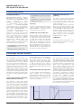
Series D from 60 to 200 kVA
UPS Catalogue
Important note!
The technical data enclosed is for general information.
Please note that the operating instructions and references
indicated on the products are for installation, operation and
maintenance.
Product designations
All product designations used are trademarks or product
names of Chloride Group PLC or its subsidiary companies.
This publication is issued to provide outline information and
is not deemed to form any part of any offer or contract.
The company has a policy of continuous product
development and improvement and we therefore reserve
the right to vary any information quoted without prior notice.
Person to contact
Uninterruptible Power
Supply Systems
UPS Catalogue • 2007
Series D
from 60 to 200 kVA
01
Scope
2
System Description
2
Device Description
3
General Requirements
5
AC/DC IGBT Converter (Rectifier)
5
DC/DC IGBT Converter (Booster/Battery Charger)
6
DC/AC IGBT Converter (Inverter)
7
Electronic Static Switch (Bypass)
8
Monitoring and Control, Interfaces
9
Mechanical Data
13
Environmental Conditions
13
Technical Data (60 to 200 kVA)
14
Options
18
Parallel Configuration
19
Appendix: Planning and Installation
21
MKA4CAT0UKD/Rev. 4-07/2008/UK
MASTERGUARD Series D
UPS Systems from 60 to 200 kVA
1 Scope
This specification describes a continuous
duty three-phase, solid state, full IGBT
(Insulated Gate Bipolar Transistor), double conversion uninterruptible power
supply (UPS) system. The UPS shall
automatically provide continuity of
electrical power, within defined limits
and without interruption, upon failure
or degradation of the commercial AC
source.
The continuity of conditioned electric
power shall be delivered for the time
period defined by the battery system.
The rectifier, the inverter, and other
mission critical converters within the
UPS, are driven by vector control algorithms (covered by patents 95 P3875,
95 P3879 and 96 P3198) running on
dedicated digital signal processor
(DSP) systems.
2 System Description
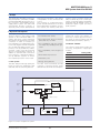
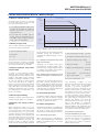
The single line diagram of the UPS is
shown in Figure 1. The systems shall
operate on two DSP-driven IGBT converters. The vector control technology
will enhance the performance of these
converters. In order to increase system redundancy, an independent electronic static bypass shall be integrated
into the UPS. By adding system components, such as parallel kits, CROSS
switches, safety and disconnecting
devices, system bypass switches, in
addition to software and communications solutions, it shall be possible to
set up elaborate systems to ensure
the complete protection of the loads.
• Increased power quality
• Full input Power Factor Correction
(PFC) and very low THDi
• Full compatibility with any installation and/or any standby power generator
• Full compatibility with all types of
loads
• Power blackout protection
• Full battery care
• Energy saving features.
2.1 The system
The UPS shall provide high quality AC
power for electronic equipment loads
and shall offer the following features:
The UPS shall automatically provide
continuity of electrical power, within
defined limits and without interruption,
upon failure or degradation of the commercial AC source. The duration of
autonomy (i.e. back up power time) in
the event of network failure shall be
determined by the battery capacity.
2.2 Models available
The Series D range shall include the
following three-phase input/output
models:
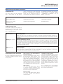
MODEL
Rating (kVA)
Series D/60
60
Series D/80
80
Series D/100
100
Series D/120
120
Series D/160
160
Series D/200
200
Maintenance Bypass
Bypass
Input
Bypass static
switch
Output
Load
Primary
Input
Fuse
IGBT
Rectifier
IGBT
Inverter
Booster/Battery charger
Battery Fuse
LIFE.net
Connectivity
bundled.
Basic signalling
Battery Fuse
Battery System
Figure 1. Series D single block system
MKA4CAT0UKD/Rev. 4-07/2008/UK
02
Optional remote
Connectivity
(IP; SNMP; J-BUS;
PROFIBUS;Etc.)
MASTERGUARD Series D
UPS Systems from 60 to 200 kVA
3 Device Description
Series D is the result of an innovative
research and development programme
designed to offer users the most reliable power supply at a minimum cost
and the highest possible energy conversion efficiency.
3.1 Components
The UPS shall consist of the following
major components:
• IGBT Rectifier
• IGBT Battery Charger / Booster
• IGBT inverter
• Dedicated digital signal processor
(DSP) control systems for each
IGBT converter
• Electronic static switch and bypass
supply
3.3.1 Double Conversion Mode
(DCM)
3.3.1.1 Normal (DCM)
The UPS inverter continuously supplies the critical AC load. The rectifier
derives power from the commercial
AC source and converts it into DC
power for the inverter and the battery
charger. The Battery Charger keeps the
Battery in a fully charged and optimum
operational condition. The inverter converts the DC power into clean and regulated AC power which is supplied to
the critical load (conditioned line). The
static switch monitors and ensures
that the inverter tracks the bypass supply frequency. This ensures that any
automatic transfer to the bypass supply (due to an overload etc.) is frequency synchronised and does not
cause interruption to the critical load.
3.3.1.2 Overload (DCM)
• Manual
switch
maintenance
3.3.2 Digital Interactive Mode (DIM)
If priority has been set to digital interactive mode, intelligent double conversion technology shall allow Series D to
continuously monitor the condition of
the input supply including its failure
rate to ensure maximum reliability for
critical users. On the basis of the
analysis performed, it shall decide
whether to supply the load through the
direct line or the conditioned line.
This operational mode, which allows
significant energy savings by increasing the overall AC/AC efficiency of the
UPS, is primarily intended for general
purpose ICT applications. However, it
does not provide the same output
power quality as when the UPS operates in double conversion mode.
Therefore it will be necessary to verify
whether this mode is appropriate for
special applications. Digital interactive
mode is not available for parallel systems.
bypass
• Matching battery cubicles
3.2 Microprocessor control and
diagnostics
In the event of an inverter overload,
manual stop or failure, the static
switch shall automatically transfer the
critical load to the bypass line without
interruption.
3.3.1.3 Emergency (DCM)
Operation and control of the UPS shall
be provided through the use of microprocessor-controlled logic. Indications,
measurements and alarms, together
with battery autonomy, shall be shown
on an illuminated, forty character liquid
crystal display (LCD). The procedures
for start up, shutdown and manual
transfer of the load to and from bypass
shall be explained in clear step-by-step
sequences on the LCD display.
3.3 Intelligent double conversion
operating modes
Series D shall adopt intelligent double
conversion technology which allows
the UPS to operate in double conversion or digital interactive mode according to the selected priority.
The UPS will operate as follows:
Upon failure or reduction of the commercial AC source (see the Technical
Data table for tolerances) the inverter
shall supply the critical load, drawing
power from the associated battery
through the battery Booster. There
shall be no interruption to the critical
load upon failure, reduction or restoration of the commercial AC source.
While the UPS is powered by the batteries, indications shall be provided of
actual autonomy time remaining as
well the duration of the mains failure.
3.3.1.4 Recharge (DCM)
3.3.2.1 Normal (DIM)
The operating mode will depend on
the quality of the mains supply in the
short-term past. If the line quality has
remained within permitted tolerance
parameters in this timeframe, the
direct line will provide continuous supply to the critical AC load through the
bypass static switch. The IGBT inverter
control will remain in constant operation and synchronisation with the
direct line without driving the IGBT.
This ensures that the load can be
transferred to the conditioned line
without any break in supply where
there is a deviation from the selected
input power tolerance levels. If the
direct line failure rate has been outside
permitted parameters, Series D shall
supply the load from the conditioned
line. The battery charger supplies the
energy necessary for maintaining maximum charge to the battery.
Upon restoration of the commercial
AC source, even where batteries are
completely discharged, the rectifier
shall restart automatically, 'walk in'
and gradually take over both the inverter and battery charger. This function
shall be fully automatic and shall cause
no interruption to the critical load.
03
MKA4CAT0UKD/Rev. 4-07/2008/UK
MASTERGUARD Series D
UPS Systems from 60 to 200 kVA
3 Device Description
3.3.2.2 Inverter stop (DIM)
If the inverter is stopped for any reason there is no transfer to the conditioned line and the load continues to
be supplied by the direct line. The
mains voltage and frequency values
must be within the tolerance limits
specified.
ditioned line for a period of time
dependant on the direct line failure
rate (the conditioned line draws power
from the mains not the battery).
When the direct line has stabilised,
Series D returns to normal operation.
The battery charger automatically
begins to recharge the battery, so that
maximum autonomy is guaranteed in
the shortest possible time.
This will thus render possible the realtime control of the inverter electronics,
resulting in obvious advantages concerning the performance of the power
components. These advantages will
be:
• Improvement of short circuit
behaviour, as individual phases can
be more quickly controlled
3.3.2.3 Overload (DIM)
3.3.3 Maintenance bypass
In the event of an overload with a duration in excess of the maximum capacity specified for the bypass static
switch, the load is maintained on the
direct line and a warning message on
the LCD display will appear (F52) to
warn the user about the potential risk
related to this condition. This default
behavior can be changed (via a Service
accessible firmware setting) to force a
load transfer to the conditioned line
(similar to that described below) even
if the bypass source is available. In the
event of an overload in conjunction
with an unsuitable bypass mains supply, Series D shall transfer the load
from the direct line to the conditioned
line (assuming Series D was operating
from the direct line) and the inverter
shall continue to supply the critical
load for a period dependant on the
degree of the overload and the UPS
features. Visual and audio alarms alert
the user to the problem.
3.3.2.4 Emergency (due to mains
supply failure or variance beyond
tolerance limits, DIM)
If Series D is supplying the load via the
direct line and the bypass mains supply varies beyond tolerance levels
(adjustable using the software), the
load will be transferred from the direct
line to the conditioned line. The load is
powered from the mains via the rectifier and inverter, (provided the input
mains remains within the tolerances
stated in tables 11 and 12). Should the
input mains falls below the lower limit
the batteries shall be used to power
the load via the inverter. The user is
alerted to the battery discharge by
visual and audio alarms and the
remaining autonomy is displayed on
the LCD. During this process, it is possible to extend the remaining autonomy by switching off non-essential
loads.
If for any reason it is necessary to take
the UPS out of service for maintenance or repair, the UPS shall be fitted
with an internal maintenance bypass
switch which enables a load transfer to
a bypass supply with no interruption to
power to the critical load. Bypass isolation shall be complete, all serviceable components such as fuses,
power modules etc. shall be isolated.
Transfer/retransfer of the critical load
may be accomplished by automatic
synchronisation of the UPS to the
bypass supply and paralleling the
inverter with the bypass source,
before opening or closing the bypass
switch as appropriate.
3.3.4 Operation without battery
If the battery is taken out of service for
maintenance, it has to be disconnected from the UPS by means of an external switch (e.g. situated in the battery
cabinet).
The UPS will continue to operate and
meet the performance criteria specified with the exception of the battery
backup time.
When the mains supply returns to
within tolerance limits, Series D will
continue to supply the load via the conMKA4CAT0UKD/Rev. 4-07/2008/UK
• High flexibility in parallel operation:
parallel blocks may be housed in
separate rooms.
Several algorithms included in the
Vector Control firmware are covered
by patents owned by MASTERGUARD
(95 P3875, 95 P3879 and 96 P3198).
3.4.2 Redundancy, preventive
monitoring
In order to maximise the reliability of
the system, the control unit shall monitor a wide number of operating parameters for the rectifier, inverter and
battery. All vital operating parameters,
such as temperatures, frequency and
voltage stability at the system input
and output, load parameters and internal system values shall be constantly
monitored and controlled for irregularities at all times. The system shall react
automatically before a critical situation
arises either for the UPS or the load, in
order to ensure the supply of the load
even in these difficult conditions.
3.4 Control and diagnostics
Control of the power electronics modules shall be optimised in order to provide:
• optimum three-phase supply of the
load
• controlled battery charging
• minimum phase effects upon the
supply network.
By using digital signal processors
(DSP) Series D shall implement the
most advanced digital control.
3.4.1 Vector control
3.3.2.5 Return to normal conditions
(DIM)
• Synchronism or phase angle precision between UPS output and
bypass supply even in the case of a
distorted mains voltage
To ensure the quick and flexible processing of measuring data, special
arithmetic algorithms shall be implemented in DSP, rapidly generating controlled variables as a result.
04
3.4.3 Telediagnosis and
telemonitoring
In all the above modes of operation,
the UPS may be monitored and controlled from a remote location such as
a service centre, in order to maintain
the reliability of the system at nominal
levels. Even during complete shutdown of the UPS, information relating
to the operating parameters shall not
be lost thanks to non volatile RAMs,
which will store the information for up
to 10 years.
MASTERGUARD Series D
UPS Systems from 60 to 200 kVA
4 General Requirements
4.1 Applied standards
MASTERGUARD operates a Quality
Management System which complies
with BS EN ISO 9001-2000 for the
manufacture,
sales,
design,
installation, maintenance and service
of uninterruptible power supply
systems.
The MASTERGUARD
Environmental Policy and Management Systems comply with EN ISO 14
001
and
MASTERGUARD
is
committed to implementing a policy of
improvement
to
continuous
production processes and pollution
reduction. Series D shall carry the CE
mark in accordance with the Safety
and
EMC
Directives
2006/95
(superseding the 73/23 and successive
amendments), 89/336, 92/31 and
93/68. Series D is designed and
manufactured in accordance with the
following international standards:
• IEC/EN62040-1-1 general and safety requirements
• IEC/EN62040-3 operating requirements.
• Classification according to IEC/EN
62040-3: VFI-SS-111
4.2 Safety
In terms of general and safety requirements, the UPS conforms to standard
IEC/EN 62040-1-1 governing use in
unrestricted access locations.
4.3 EMC and surge suppression
Electromagnetic effects shall be minimised in order to ensure that computer systems and other similar electronic loads shall neither be adversely
affected by nor affect the UPS. The
UPS shall be designed to meet the
requirements of EN 50091-2, class RS.
The manufacturer and customer in
partnership agree to ensure the essential EMC protection requirements for
the specific resulting installation.
4.4 Neutral connection and
grounding
The Series D output neutral shall be
electrically isolated from the UPS chassis. The input and output neutral connections are the same, i.e. they are
solidly tied together.
Therefore the UPS shall not modify the
state of the upstream neutral, in any
operating mode, and the neutral state
of the distribution downstream from
the UPS is imposed by the mains one.
Series D shall be used in installations
with grounded neutral; for further
details please contact MASTERGUARD Technical Support.
4.5 Materials
All materials and components comprising the UPS shall be new and of
current manufacture.
• EN50091-2 EMC requirements
5 AC/DC IGBT Converter (Rectifier)
5.1 Primary input
The three-phase current taken from
the commercial AC source shall be
converted to a regulated DC voltage by
an IGBT rectifier. In order to protect
the power components within the system each phase of the rectifier input
shall be individually fitted with a fastacting fuse. As shown in Figure 1, the
IGBT rectifier shall provide DC power
to the DC/AC output converter (IGBT
inverter) and to the DC/DC battery converter (booster / battery charger) when
the latter is working in battery charger
mode.
5.2 Total Input Harmonic Distortion
(THD) and Power Factor (PF)
The maximum voltage THD (THDV)
permitted on the rectifier input (either
from the utility or generator) shall be
15% (normal operation is guaranteed
up to 8%). The maximum current THD
injected into the mains (THDI) shall be
less than 3% at maximum input power
and input voltage THDV < 1% (nominal
input voltage and current). Under
these conditions the input power factor (PF) will be > 0.99. Under other
input conditions and with other output
load fractions the THDI will be < 5%.
This means that the Series D in double
conversion mode shall be seen by the
primary mains sources and distribution
as a resistive load (i.e. it will absorb
only active power and the current
waveform will be practically sinusoidal), thus ensuring total compatibility with any power source. Series D
includes all the performances offered
by load active filtering devices as standard.
5.3 Operation with diesel generator
In order to obtain the required THD on
input voltage, the coordination
between diesel generator and UPS
shall be based on the generator’s subtransient reactance, as opposed to its
short-circuit reactance.
AC
Input
Current
5.4 Soft start
With the UPS logic properly powered,
after applying the input voltage the rectifier starts an additional programmable
current soft start (1-90 seconds). This
procedure results in a gradual and soft
walk-in of the current taken from the
input voltage supply network. This
ensures that any standby generator is
gradually introduced into the UPS input,
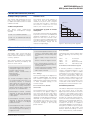
as shown in Figure 2. To avoid the simultaneous start-up of different rectifiers, it
is possible to programme a hold-off
dedicated start delay (1-180 seconds)
for each unit. In addition, the UPS
includes an ‘on generator’ function
which, when activated via floating contact, provides the possibility of inhibiting either battery charging, synchronisation of the inverter to the direct line supply or transfer to the direct line.
Hold-off
Delay
(1- 180s)
Mains Failure
Current
soft
start
(1-90 s)
Mains OK
Time
Figure 2. Rectifier soft start
05
MKA4CAT0UKD/Rev. 4-07/2008/UK
MASTERGUARD Series D
UPS Systems from 60 to 200 kVA
6 DC/DC IGBT Converter (Booster / Battery Charger)
6.1 Booster / Battery Charger
As can be seen in Figure 1, this bidirectional IGBT DC/DC converter shall
have the following functions:
• To recharge the batteries taking the
power from the DC bus, when the
primary input mains is within the
given tolerances
• To provide the suitable full DC
power, taken from the batteries, to
the IGBT output inverter if the primary mains is unavailable.
6.2 Battery charger mode
(Nominal Voltage)
Input AC
Voltage
100%
85%
80%
Time
Battery
status
Charging/
floating
idle
(no discharge)
This converter shall be operable with
the following types of batteries:
T1
T2
Time
Figure 3. Battery status during reduction of the commercial AC source.
• Sealed Lead Acid (VRLA)
• Lead Acid
• Ni - Cd
The selection of the optimum charging
method shall be completely managed
by the microprocessor. Several different charging methods are available.
6.3 Voltage regulation, temperature
compensation
In order to ensure optimum battery
charging, float voltage shall be automatically adjusted to the ambient temperature. The IGBT rectifier shall be
capable of supplying the battery charger with DC voltage at rated power,
even if the UPS input AC voltage is
below the nominal voltage specified. A
further reduction of the input AC voltage (within specified limits) will inhibit
the battery charger but will not require
the discharging of the batteries. See
Figure 3 for details.
are an example of the several methods
available, giving the possibility of
matching the different types of accumulators:
When the primary mains is not suitable to supply the rectifier, the DC/DC
converter (booster mode) will provide
the required power to the inverter
using the energy stored in the battery.
After the discharge of the battery and
when the input AC power is restored,
the rectifier will power the inverter and
recharge the batteries through the
DC/DC converter in battery charger
mode. The following charging methods
MKA4CAT0UKD/Rev. 4-07/2008/UK
• Shutdown imminent alarm (V) 1.75
• Minimum battery test voltage
(V) 1.9
Charging is at constant current up to
the maximum floating voltage level.
Thereafter the voltage shall be kept at
a constant level within narrow limits
(single-step charging method).
• Nominal voltage
(V) 2.0
• Battery discharging alarm (V) 2.20
@ 20°C
• Float voltage
6.5.2 Sealed, low-maintenance lead
acid accumulators or NiCd accumulators:
(V) 2.27 @ 20°C
• High voltage alarm
(V) 2.4
6.7.2 Automatic battery test
Charging is at increased charging voltage and constant charging current
(boost charge phase). When the charging current falls short of a lower threshold value the battery charger shall automatically return to floating voltage level
(two-step charging method).
6.6 Overvoltage protection
6.5 Capacity and charging characteristics
(V) 1.65
6.5.1 Sealed, maintenance-free lead
acid accumulators:
6.4 Residual ripple filtering
The battery charger output shall have a
residual voltage ripple of <1% RMS.
• End of discharge voltage
The battery charger shall automatically
switch off if the DC battery voltage
exceeds the maximum value associated with its operational status.
6.7 Battery management
Using advanced battery care (ABC) the
Series D series shall increase battery
life by up to 50%. The main battery
care features are described as follows.
The operating condition of the
batteries shall be automatically tested
by the control unit at selectable
intervals, e.g. weekly, fortnightly or
monthly. A short-time discharge of the
battery will be made to confirm that all
the battery blocks and connecting
elements are in good working order.
In order to preclude a faulty diagnosis
the test will be launched 24 hours after
the latest battery discharge at the
earliest. The battery test shall be
performed without any risk to the load,
even if the battery is completely
defective. Users shall be alerted to a
detected battery fault. The battery test
shall not cause any degradation in terms
of the battery system life expectancy.
6.7.3 Ambient temperature
compensated battery charger
6.7.1 Operating parameters
When operating with a maintenance
free, valve regulated lead acid battery
(VRLA), the parameters per cell shall
be as follows:
06
The float voltage shall be automatically
adjusted as a function of the temperature in the battery compartment
(-0.11% per °C) in order to maximise
battery operating life.
MASTERGUARD Series D
UPS Systems from 60 to 200 kVA
6 DC/DC IGBT Converter (Booster / Battery Charger)
6.7.4 Time compensated end of discharge voltage
When the discharge time exceeds one
hour, the shutdown voltage shall be
automatically increased, as shown in
Figure 4 for VRLA, to avoid prolonged
battery discharge as a result of a light
load.
in parallel) is equal to or greater than
20% (based on the UPS default battery recharging values). In any case
this configuration is not recommend-
ed due to the negative impact on the
overall system reliability caused by the
lack of redundancy of the battery
banks.
Voltage per cell
1.80
6.7.5 Remaining battery life
Series D uses sophisticated algorithms to determine the battery life
remaining based on real operating
conditions such as temperature, discharge and charging cycles, and discharge depth.
1.75
1.70
6.7.6 Operations with shared battery
bank
Although this configuration is not recommended, it is possible to share a
common battery bank between a maximum of two UPS connected in parallel (see chapter 14 for details about
parallel systems). The automatic battery test (see 6.7.2) will be significant
if the total system load (of the 2xUPS
1.65
0
1
2
3
4
5
6
7
8
9
10
Time (hours)
Figure 4. End-of-discharge voltage in relation to discharge time
7 DC/AC IGBT Converter (Inverter)
7.1 AC voltage generation
7.2.2 Voltage transient response
7.4 Total Harmonic Distortion
From the DC voltage of the intermediate circuit the inverter shall generate
sinusoidal AC voltage for the user load
on the basis of pulse-width modulation
(PWM). By means of the digital signal
processor (DSP) of the control unit the
IGBT of the inverter shall be controlled
so that DC voltage is divided up into
pulsed voltage packets. Thanks to a
low-pass filter the pulse-width modulated signal shall be converted into
sinusoidal AC voltage. No isolation
transformer is needed for the IGBT
inverter, with the great benefits of:
energy conversion efficiency, physical
size and weight of the modules.
The inverter transient voltage shall not
exceed Class 1 limits when subjected
to application or removal of 100% load
as defined by IEC/EN62040-3.
The inverter shall provide harmonic neutralisation and filtering to limit the THD
on the voltage to less than 3% with a
linear load. For reference non-linear load
(as defined by IEC/EN62040-3) the THD
shall be limited to less than 5%.
7.3 Frequency regulation
The inverter output frequency shall be
controlled to achieve the following performances:
7.3.1 Steady state
The inverter steady-state output frequency, when synchronised to bypass
supply, shall not deviate by more than
±1% adjustable to ±2%, ±3%, ±4%.
7.2 Voltage regulation
7.5 Neutral sizing
The sizing of the inverter neutral shall
be oversized on all ratings in order to
cope with the combination of harmonics on the neutral wire when driving
single-phase reference non-linear
loads. The inverter neutral is sized x 1.7
in relation to the phase.
7.6 Overload
7.3.2 Frequency slew rate
The inverter output voltage on the
three phases shall be individually controlled to achieve the following performances:
The frequency slew rate shall be <1 Hz
per second.
The inverter shall be capable of supplying an overload of 125% for 10 minutes and 150% for one minute of the
nominal power.
7.3.3 Frequency slew rate
7.7 Inverter shutdown
7.2.1 Steady state
The inverter steady state output voltage shall not deviate by more than
±1% in a steady state condition for
input voltage and load variations within
the quoted limits.
The output frequency of the inverter
shall be controlled by a quartz oscillator which can be operated as a free
running unit or as a slave for synchronised operation with a separate AC
source. The accuracy of the frequency
control shall be ±0.1% when free-running.
07
In the event of an internal failure the
inverter shall be immediately shut down
by the control unit. The UPS device or
the parallel-operated UPS systems shall
continue to supply the load from the
bypass supply without interruption, if it
is within permissible limits.
MKA4CAT0UKD/Rev. 4-07/2008/UK
MASTERGUARD Series D
UPS Systems from 60 to 200 kVA
7 DC/AC IGBT Converter (Inverter)
7.8 Output voltage symmetry
7.10 Short circuit
The inverter shall guarantee the symmetry of the output voltages at ±1%
for balanced loads and ±3% for 100%
unbalanced loads.
The inverter short circuit capacity of
Series D for the first 10ms shall be
>200% for any short circuit configuration. After the first 10ms, it shall limit
the current to >150% for not more
than 5s, then it shall shut down.
7.9 Phase displacement
Output Power
115
112
The phase angle displacement
between the three-phase voltages
shall be:
• 120° ± 1° for balanced loads
• 120° ± 3° for unbalanced loads (0,
0, 100%)
7.11 Automatic upgrade of inverter
rated power
110
105
The inverter shall automatically upgrade
its power as a function of ambient and
operating temperatures, as shown in
Figure 5. In the most common conditions (25°C) Series D shall provide 10%
more power than nominal. In these conditions the battery charge will be
reduced correspondingly.
Ambient
Temperature
100
15
25
30
40
Figure 5. Automatic power upgrade
8 Electronic Static Switch (Bypass)
8.1 General
The bypass static switch shall be a
fully rated, high speed, solid-state
transfer device and rated for continuous duty operation.
The following transfer and retransfer
operations shall be provided by the
electronic static switch:
• Uninterrupted automatic transfer to
the bypass supply in the event of:
- inverter output overload
- battery voltage outside limits in
backup mode
- over-temperature
- inverter failure
• If inverter and bypass supply are
not synchronised at the time of a
necessary transfer, a switching
delay can be set to protect the critical load. This prevents possible
damage to the load by unintentional phase shift. A delay of 20ms will
be preset as a standard value.
• Uninterrupted manual transfer/
retransfer to and from the bypass
supply shall be initiated from the
control panel.
• Uninterrupted automatic transfer/
retransfer to and from the bypass
supply by activation of the digital
interactive mode
8.1.3 Overload
• The uninterrupted transfer from the
inverter to the bypass supply shall
be inhibited in the following situations:
- bypass supply voltage outside limits
- failure of electronic bypass switch
• The uninterrupted automatic retransfer may be inhibited in the following situations:
- manual switching to bypass supply
via the maintenance switch
- UPS output overload.
8.1.1 Voltage
The nominal voltage of the bypass line
shall be 230/400 VRMS. Any transfer
from inverter to bypass line will be
inhibited if the voltage is beyond a limit
of ±10% (standard setting) of the
nominal voltage.
8.1.2 Transfer time (double
conversion)
The switching time for a transfer from
the inverter to the bypass supply or
vice versa shall be less than 0.5ms
when synchronised. The system shall
ensure that the inverter is stable and
operating normally before permitting a
retransfer of the load back to inverter.
The transfer time when out of synchronisation shall be 20 milliseconds
to prevent damage to the load by
phase reversal.
• Uninterrupted automatic retransfer
from the bypass supply, as soon as
the inverter regains the capacity to
supply the load
MKA4CAT0UKD/Rev. 4-07/2008/UK
08
The bypass static switch shall be capable of supporting the following overloads:
125%
150%
700%
1000%
for
for
for
for
10 minutes
1 minute
600 milliseconds
100 milliseconds
8.1.4 Manual maintenance bypass
It shall be possible to implement a
manual uninterrupted bypass of the
complete system in order to enable
maintenance work to be carried out on
the system. The bypass supply will
continue to feed the load. In this case
the UPS will be voltage-free as it will
be disconnected from the supply networks. In this case, maintenance work
on the UPS can be carried out without
affecting the connected electric load.
8.2 Backfeed protection
This feature shall prevent any potential
risk from electric shock on the UPS
bypass input AC terminals in the event
of failure of the bypass static switch
SCR. The control circuit shall include a
contact (available for the user) which
activates an external isolating device,
such as an electromechanical relay or a
tripping coil, upon backfeed detection.
The external isolating device is not
included in the UPS, in compliance
with IEC/EN 62040-1. The external isolating device shall be a 4 pole (3 phases plus neutral) air gap isolator, and
shall be defined according to clause
5.1.4 of the previously cited standard.
MASTERGUARD Series D
UPS Systems from 60 to 200 kVA
9 Monitoring and Control, Interfaces
This navigation group includes two
buttons - “up” and “down” - for menu
scrolling and two software-assigned
push buttons: the function linked to
these two buttons is displayed on the
lower right and lower left corners of
the LCD during navigation.
9.1 General
The UPS shall incorporate the
necessary controls, instruments and
indicators to allow the operator to
monitor the system status and
performance, and take action where
appropriate. Furthermore, interfaces
allowing extended monitoring and
control, in addition to service
functions, shall be available.
A single-line diagram of the UPS is
continuously displayed on the default
page (for reference see figure 1). The
main functional blocks and power
paths of the UPS are displayed using
simple universal technical symbols,
instantly communicating the overall
status of the UPS. The same screen
also permanently displays the output
load percentage measurement, using
three histograms (one for each output
phase). In the case of the UPS not in
normal functioning mode, it is possible
to access the “Warning and Alarm”
9.2 Mimic panel
The control panel of Series D includes
a back-lit Liquid Crystal Display (LCD of
eight lines x 12 characters, displaying
graphic diagrams and symbols) for
complete UPS monitoring and control.
Complete access to all LCD menus is
possible through navigation push
buttons located below the screen.
summary page directly from the
default page. Warnings and alarms
shall be identified by text strings and
codes. In battery operation, the display
shall switch between warning code
and estimated backup time in minutes.
After 30 seconds of inactivity (i.e.
without buttons being pressed) the
display reverts to the default page.
The text displayed by the LCD shall be
available in English, Italian, French,
German, Spanish, Portuguese, and
Turkish, selectable by the user.
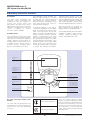
Graphical LCD
screen
Navigation buttons:
left soft-key,
up and down button,
right soft-key
“Inverter Off” push
button
“Inverter On”
push button
“Alarm” LED
“System Normal”
LED
ON
“Reset” push button
(e.g. audible signal
silence for warning
and alarm conditions)
OFF
Commands key lock
“Warning” LED
KEYBOARD
9.3 Start and Stop inverter push
buttons
Start inverter operation
The Start and Stop push buttons are
integrated into the mimic panel board,
and have the following predefined
functions:
Stop inverter operation
09
The control shall incorporate a safety
feature to prevent inadvertent operation yet still allow for rapid shutdown in
the event of an emergency. To stop the
inverter the user must press and hold
the Stop button for two seconds. An
audio alarm shall be activated during
this delay time.
MKA4CAT0UKD/Rev. 4-07/2008/UK
MASTERGUARD Series D
UPS Systems from 60 to 200 kVA
9 Monitoring and Control, Interfaces
The mimic panel shall be equipped
with a front panel key that allows
users, once the lock is set in the Off
position, to disable any command
which may be entered through the
mimic panel. In this state, if the opera-
tor attempts to perform any of the following actions, a message reading
“COMMANDS DISABLED” will be
appear on the LCD:
Start Inverter
Stop Inverter
Reset Fault
Set/reset Battery Test
Set/reset Autonomy Test
Set/reset Boost Charge
Set/reset Service Input
Set/reset I/O Configuration
LIFE Manual Call
9.4 Keyboard lock
Reset Delay Call
9.5 General Status LED
Three LED indicators shall render it
possible to obtain a quick and general
understanding of the status of the
UPS, as described below:
OK LED (green)
Normal Operation
When this light is on (not flashing), the system is running normally and neither warnings nor
alarms are present. During mains failures (all other conditions being at nominal level), this LED
will flash.
Warning LED (yellow)
Warning Condition(s) present
This indication shall be activated by the presence of anomalous conditions, which could affect
the nominal functioning of the UPS. These conditions are not originated with the UPS, but may
be caused either by the surrounding environment or by the electrical installation (mains side and
load side). It shall be possible to read the description of the active warning(s) by browsing the
relevant LCD display menus.
Alarm LED (red)
Alarm Condition
When this light is on, immediate attention should be given to the severity of the alarm, and
service should be called promptly. It shall be possible to read the description of the active
alarm(s) by browsing the relevant LCD display menus.
9.6 LCD display menus description
By using the appropriate push buttons
it shall be possible to browse the following menus:
IGBT Rectifier and Booster/Battery
Charger converter
This menu shall display rectifier status,
booster/charger status, alarms, voltage, total DC current, battery current
with polarity and battery temperature.
When the output inverter is supplied
by the battery, the module shall display
remaining autonomy time. A change in
load shall cause the autonomy indicator to display the new autonomy time.
Load/Bypass Static Switch
This menu shall display alarms, current
per phase, frequency measurements,
load percentage capacity per phase
and the peak factor Ipk/Irms for each
phase of the load current. It shall be
possible to display the total time the
load has been supplied by the inverter,
and by bypass, the number of mains
failures and the total duration of these
failures.
IGBT Inverter
This menu shall display alarms, phase
to neutral voltages, frequency measurements, inverter heatsink temperature and cooling air temperature.
For a complete list of the messages
and menu descriptions, please refer to
the Series D User Manual.
Bypass Supply
This menu shall display alarms, phase
to neutral voltages and frequency
measurements.
MKA4CAT0UKD/Rev. 4-07/2008/UK
10
MASTERGUARD Series D
UPS Systems from 60 to 200 kVA
9 Monitoring and Control, Interfaces
9.7 Interface
9.7.1 Slot card bay
Series D shall be equipped with two
slot bays, available for communication
card options. One of the slots shall be
equipped with the LIFE.net slot
modem, fitted as standard (user
removable).
The other slot shall be available for
connectivity options. Please refer to
MASTERGUARD
Connectivity
Solutions for further details about the
available slot expansion cards. If no
cards are fitted into the slots, the DB9
ports described in sections 9.7.3 and
9.7.4 can be used for other connectivity applications.
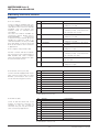
Pin
1
Signal
BYPASS ACTIVE (NC)
2
LOW BATTERY (NC)
3
SUMMARY ALARM (NC)
4
AC FAIL (NC)
5
COMMON
Common connection for all floating
contacts
6
BYPASS ACTIVE (NO)
Bypass mode: contact between pin 6
and pin 5 is open
7
LOW BATTERY (NO)
9.7.2 Computer relay interface (X7)
Volt-free contacts shall be incorporated conforming to the requirements of
IBM AS/400 and other computer
types. This interface shall be via a 9-pin
D socket wired as follows:
8
SUMMARY ALARM (NO)
9
AC FAIL (NO)
Explanation
Bypass mode: contact between pin 1
and pin 5 is closed
Just before end of discharge
(in battery mode): contact between
pin 2 and pin 5 is closed
UPS alarm, contact between pin 3
and pin 5 is closed
Mains failure: contact between pin 4
and pin 5 is closed
Just before end of discharge
(in battery mode): contact between
pin 7 and pin 5 is open
UPS fault, contact between pin 8 and
pin 5 is open
Mains failure: contact between pin 9
and pin 5 is open
The voltage-free contacts shall be rated at 24V, 1A.
9.7.3 RS232C Service port (X3)
Series D shall be equipped with one D
type connector with 9 pins for serial
RS232C communication. The connector has the following pin functions:
Pin
Signal
Explanation
1
EARTH
Shield
2
TxD
Send RS232
3
RxD
Receive RS232
4
Not used
5
RS232 GND
6
Not used
7
RTS
8
Not used
9
Not used
Signal ground for receive and send
Clear to send RS232
This RS232 port cannot be used simultaneously with the corresponding slot bay
as described in section 9.7.1.
9.7.4 LIFE.net (X6)
Series D shall be fitted with a slot
modem for LIFE.net connection as
standard. If this slot modem is
removed, this port may be used for
other connectivity applications.
Pin
Signal
Explanation
1
SHIELD
Cable shield
2
SST2_TRS232
Send RS232 (Tx)
3
SST2_RRS232
Receive RS232 (Rx)
4
Not used
5
Not used
6
Not used
7
M_BT
8
Not used
9
Not used
Signal ground
This RS232 port cannot be used simultaneously with the corresponding slot bay
as described in section 9.7.1.
11
MKA4CAT0UKD/Rev. 4-07/2008/UK
MASTERGUARD Series D
UPS Systems from 60 to 200 kVA
9 Monitoring and Control, Interfaces
9.8 Available signalisations and
control signals
The UPS handles 6 Input/Output digital
control signals (4 inputs, 2 outputs)
that can be programmed via the
display and/or PPVIS (service software
tool) for a wide set of functions. The
inputs are opto-isolated and can be
driven by external dry-contacts (e.g.
relay contacts); the outputs are relay
contacts rated 1A, 230V AC/DC.
Emergency Power Off (EPO) is
programmed as standard: this
command electronically shuts down
the rectifier, the inverter and the
bypass
switch.
The
backfeed
protection control (see paragraph 8.2)
command is associated with a
dedicated contact output terminal
(refer to the User Manual for further
details).
9.9 LIFE.net
In order to increase the overall reliability of the system, Series D will be
delivered with the LIFE.net communication kit, providing connection to
MASTERGUARD’s LIFE.net diagnostic
service.
LIFE.net shall allow the remote diagnosis
of the UPS through telephone lines or
GSM link in order to ensure maximum
reliability of the UPS throughout its
operational life. The monitoring shall be
a real 24-hour, 365 day service thanks
to a unique feature that allows trained
Service Engineers to remain in constant electronic contact with the service centre, and therefore the UPS.
The UPS shall automatically dial up the
service centre at defined intervals to
provide detailed information that shall
be analysed in order to predict near
term problems. In addition, it shall be
possible to control the UPS remotely.
The communication of UPS data to the
MKA4CAT0UKD/Rev. 4-07/2008/UK
Listed below are the most significant functions; the exhaustive list is published in
the User Manual:
Fan (On-Off) In Battery Compartment
Battery Fuse Monitor
Battery Compartment Overheated
Generator On
Hydrogen Present
Remote Inverter Stop
SBS Bypass Switch Closed
Air conditioning failure
SBS Output Switch Open
MASTERGUARD LIFE Command
Centre shall take be transmitted via
the integrated modem at the following
intervals:
• ROUTINE: settable at intervals of
between five minutes and two
days (typically once a day)
• EMERGENCY: when a problem
occurs or parameters are beyond
tolerance limits
The service centre shall analyse historical data and issue a regular detailed
report to the customer informing him
of the UPS operational condition and
any critical states.
The LIFE.net centre allows the possibility of activating the LIFE-SMS delivery system option, where the customer may receive SMS notification
which will be activated in the event of
one of the following:
• Mains power failure
• MANUAL: following a request
from the command centre
During the call the command centre
shall:
• Mains power recovery
• Bypass line failure
• Load supplied by reserve.
• Identify the UPS connected
• Request the data stored in the UPS
memory since the last connection
• Request real-time information from
the UPS (selectable)
12
MASTERGUARD Series D
UPS Systems from 60 to 200 kVA
10 Mechanical Data
10.1 Enclosure
The UPS shall be housed in a spacesaving modular enclosure with front
doors and removable panels (protection as standard to IP 20). The enclosure shall be made of zintec coated
sheet steel. The doors shall be lockable.
10.2 Ventilation
Forced redundant air cooling will
ensure that all the components are
operated within their specification.
Airflow shall be controlled according to
load demand. The UPS shall also be
capable of preserving normal operations even with one cooling fan
stopped (due to a failure) with 70% of
the output nominal load @ 25°C ambient temperature.
If these conditions are not met (with
one fan failed), the UPS shall supply
the load through the static bypass if an
overheating of the converters occurs.
The failed fan condition will be
immediately notified by the UPS
through all the user interfaces and
through the LIFE.net service. The
cooling air entry shall be in the base
and the air exit at the top of the device.
The enclosure shall be installed with at
least 500 mm of free space between
the device and roof of the enclosure in
order to allow cooling air to exit
unhindered.
10.3 Cable entry
Cable entry shall be from the bottom
or bottom-side of the cabinet. Top
cable entry shall be available as an
option.
10.4 Enclosure design
All surfaces of the enclosure shall be
finished with an electrostatically
applied epoxy coat. The coating shall
have a thickness of at least 60
microns. Standard colour of the
enclosure shall be RAL 7035 (light
grey).
10.5 Access to integrated
subassemblies
All internal subassemblies shall be
accessible for typical and most
frequent maintenance from the front
of the unit via hinged doors. Rear
access shall not be required for
installation or servicing. The UPS shall
be forkliftable from the side after the
removal of the bottom trim panels.
11 Environmental Conditions
The UPS shall be capable of withstanding any combination of the environmental conditions listed below. It
shall operate without mechanical or
electrical damage or degradation of
operating characteristics.
11.1 Ambient temperature
11.3 Altitude
0° to 40°C
Maximum average daily temperature
(24 hr)
35°C
Maximum temperature
(8 hr)
40°C
The maximum altitude without derating shall be 1000 metres above sea
level (for higher altitudes Series D
complies with IEC/EN 62040-3).
11.2 Relative humidity
Up to 90% (non condensing) for
temperature of 20°C.
13
MKA4CAT0UKD/Rev. 4-07/2008/UK
MASTERGUARD Series D
UPS Systems from 60 to 200 kVA
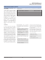
12 Technical Data (60 to 200 kVA)
UPS Unit
60
80
100
120
160
200
250
312
>96.1
>97
>95.9
>97
12.1 Primary input
Nominal voltage(1)
(V)
400 (3Ph + N(1))
Voltage range
(V)
340 to 460
Minimum voltage without battery discharge
(V)
320
Nominal frequency
(Hz)
50 (60 selectable)
Frequency range
(Hz)
±6%
Maximum input current @ ambient
temperature within the range 0°C to 40°C
(A)
94
125
156
Power factor @ nominal load &
nominal input conditions(2)
185
>0.99
Input current distortion @ nominal input
conditions(2) & nominal output power(3)
(%)
<3
Input current distortion
(%)
<5
(3) (11)
Walk in/Soft start
Rectifier Hold-Off
(seconds)
10 (1 to 90 selectable)
(seconds)
1 (1 to 180 selectable)
Inrush current / Imax input
<1
(4)
Rectifier efficiency without charging
current @ nominal input conditions(2)
with resistive load:
Half load(7)
Full load(7)
(%)
(%)
>94.9
>96.5
>96.2
>97
>95.9
>97
>96.2
>97
12.2 Battery
Permissible battery voltage range
Recommended no. of cells:
(V)
396 to 700
- VRLA(5)
- WET
- NiCd
240
240
375
Float voltage for VRLA @ 20°C(6)
(V/cell)
2.27
End cell voltage for VRLA
(V/cell)
1.65
Float voltage temperature compensation
-0.11% per °C
DC ripple current in float mode for a 10 min
autonomy as per VDE0510(5)
<0.05C10
Float Voltage stability in steady state condition
(%)
<1
DC ripple voltage without battery
(%)
<1
Optimum battery temperature
(°C)
15 to 25
Battery recharge current setting range
for 240 cells @ 400V input voltage & nominal load
(A)
0-23
0-31
0-39
0-44
0-62
0-77
Battery recharge current setting range
for 240 cells @ 340V input voltage & nominal load
(A)
0-6
0-8.5
0-10.5
0-10.5
0-17
0-21
(kW)
50.2
67
83.7
100.5
134
167,5
254
338
423
Battery output power in discharge mode
with nominal output load
End battery voltage for 240 cells
(V)
End battery current for 240 cells with nominal load
(A)
MKA4CAT0UKD/Rev. 4-07/2008/UK
396
127
14
169
211
MASTERGUARD Series D
UPS Systems from 60 to 200 kVA
12 Technical Data (60 to 200 kVA)
UPS Unit
60
80
100
120
160
200
12.3 inverter output
Nominal apparent power @40°C ambient
(kVA)
60
80
100
120
160
200
Nominal active power
(kW)
48
64
80
96
128
160
(A)
87
116
145
174
232
290
Nominal output current
Maximum active power up to 100%
of nominal apparent power
Conditions apply(10)
Overload at nominal output voltage for 10 minutes
(%)
125
Overload at nominal output voltage for 1 minute
(%)
150
Short circuit current for 10ms/<5s
(%)
200/150
(V)
400 (380/415 selectable, 3Ph+N)
Nominal output frequency
(Hz)
50 (60 selectable)
Voltage stability in steady state condition for input
(AC & DC) variations and step load (0 to 100%)
(%)
Nominal output voltage
±1
Voltage stability in dynamic condition for input variation
(AC & DC) and step load (0 to 100% and vice versa) (%)
Voltage stability in steady state for 100%
load imbalance (0, 0, 100)
Output frequency stability:
Complies with IEC/EN 62040-3, Class 1
(%)
- synchronized with
bypass mains
- synchronized with
internal clock
Frequency slew rate
±3
(%)
±1 (2, 3, 4 selectable)
(%)
±0.1
(Hz/sec)
<1
Output voltage distortion with 100% linear load
(%)
<3
Output voltage distortion @ reference
non linear load as for IEC/EN 62040-3
(%)
<5
Load crest factor handled without
derating the UPS
(Ipk/Irms)
Phase angle precision with balanced loads
(degrees)
1
(degrees)
<3
Phase angle precision with 100%
unbalanced loads
Inverter efficiency @ nominal input conditions
with resistive load:
Half load(7)
Full load(7)
3:1
(2)
(%)
(%)
>94.9
>96.5
Neutral conductor sizing
Output power upgrading
with ambient temperature:
>96.2
>97
>95.9
>97
>96.2
>97
>96.1
>97
>95.9
>97
1.7 nominal current
At 25°C
At 30°C
At 40°C
(%)
(%)
(%)
110
105
100
15
MKA4CAT0UKD/Rev. 4-07/2008/UK
MASTERGUARD Series D
UPS Systems from 60 to 200 kVA
12 Technical Data (60 to 200 kVA)
UPS Unit
60
80
100
120
160
200
12.4 Static bypass
Nominal bypass voltage(1)
(V)
400 (380/415 selectable, 3ph+N)
Nominal frequency
(Hz)
50/60 (selectable)
Frequency range
(%)
±1 (2, 3, 4 selectable)
Voltage range
(%)
±10
(%)
(%)
(%)
(%)
125
150
700
1000
Maximum overload capacity:
For
For
For
For
10 minutes
1 minute
600 milliseconds
100 milliseconds
SCR
I2t @ Tvj=125°C;
8.3-10ms
ITSM @ Tvj=125°C;
10ms
(A2s)
80000
125000
320000
(A)
4000
5000
8000
Transfer time with inverter synchronous to bypass:
Inverter to Bypass and Bypass to Inverter
Transfer time with inverter not synchronous
to Bypass
no break
(ms)
<20
12.5 System data
Maximum input current with ambient
temperature range 0°C to 40°C
(A)
94
125
156
185
250
312
(%)
(%)
(%)
(%)
(%)
82.8
90.0
92.7
93.0
98
86.0
92.5
93.0
94.0
98
87.0
92.0
93.4
94.0
98
88.0
92.5
93.8
94.0
98
88.0
92.3
93.4
94.0
98
87.0
92.0
93.0
94.0
98
(kW)
Float mode
Recharge mode
(kW)
Digital interactive mode (kW)
3.6
3.6
1
4.1
4.8
1.3
5
6
1.6
6
7.2
1.9
8
9.6
2.6
10
12
3.2
AC/AC efficiency without charging
current @ nominal input conditions(2)
with resistive load:
25% load(7)
50% load(7)
75% load(7)
100% load(7)
Digital interactive(7)
Heat dissipation
Noise @ 1 metre as per ISO 3746
(dBA ± 2dBA)
65
Protection degree with open doors
Mechanical dimensions:
(mm)
Width
(mm)
Depth
1780
580
(mm)
845
1120
1245
858
No. of cabinets
Frame colour
70
IP20
Height
(9)
68
1
(RAL scale)
7035
Weight
(kg)
290
390
500
600
Floor area
(m2)
0.47
0.70
0.96
1.07
(kg/m2)
617
557
520
560
Floor loading
MKA4CAT0UKD/Rev. 4-07/2008/UK
16
MASTERGUARD Series D
UPS Systems from 60 to 200 kVA
12 Technical Data (60 to 200 kVA)
UPS Unit
60
80
Cable entry
100
120
160
200
Bottom/Side
Access
Front
Cooling
Forced Ventilation with redundancy
(8)
12.6 Environmental
Temperature:
Operating
(°C)
0-40
Max Average daily (24hrs)
(°C)
35
Maximum (8hrs)
(°C)
40
Maximum relative humidity @ 20°C (non condensing) (%)
Max altitude above sea level without derating
up to 90
(m)
1000 (for higher altitudes complies with IEC/EN 62040-3)
(1) In case of a split input configuration, the primary input and the bypass input must have a common neutral. The neutral conductor could be connected only
to the bypass or primary mains but it must be present (bypass and primary neutrals are solidly connected within the UPS).
(2) At nominal voltage and nominal frequency.
(3) With input voltage at nominal value and with voltage distortion THDv < 1%.
(4) “Imax input” parameter can be calculated using the maximum input power @ 400V in battery recharge mode.
(5) Permitted number of cells = 240 – 300. Special battery cabinets needed for more than 240 cells.
(6) There are several possible charging methods. See chapter 6 for details.
(7) For tolerances see IEC/EN 60146-1-1 or DIN VDE 0558.
(8) Redundant cooling system. With one fan OFF the UPS can supply continuously 70% of the nominal output power in typical conditions.
(9) including front handle; without handle 830m
(10) Nominal apparent power loads with PF > 0.8 can be supplied with marginal limitations to other performances. Please contact MASTERGUARD Technical
Support for further details.
(11) Output load > 25% of nominal output power.
General conditions for the Technical Data table:
The data shown are typical and not definable in other ways; furthermore the data refer to 25°C ambient temperature and PF= 1 where not specified.
Not all the data shown apply simultaneously and may be changed without prior warning.
Data apply to the standard version, if not otherwise specified.
If the options described in chapter 13 are added, the data shown in the Technical Data Table may vary.
For test conditions and measurement tolerances not specified refer to the Witness Test Report procedure.
17
MKA4CAT0UKD/Rev. 4-07/2008/UK
MASTERGUARD Series D
UPS Systems from 60 to 200 kVA
13 Options
Where options described in this chapter are added to the UPS, the data presented in the standard technical data
tables may vary. Some options may
not be available contemporarily on the
same UPS.
reserved for other purposes (e.g. fax
or telephone).
• Cubicle
• Disconnecting device
13.11 MopUPS shutdown and monitoring software
• Fuses
The main function of MopUPS software shall be the safe shutdown of the
operating system in the event of a
power failure. Other functions include:
13.1 Parallel configurations
• Safety screen
See chapter 14.
• Connection terminals
13.2 Remote alarm unit
• UPS/battery connection cables
(available on request)
A remote alarm panel shall be available
to display important individual messages from the UPS. Upon request, it
shall be possible to display up to four
UPS systems. The length of the connecting cable must not exceed 300m.
13.3 External battery circuit breaker
This option shall include a fully rated
circuit breaker and an additional auxiliary contact for monitoring its position
by the UPS (via a dedicated input contact). The circuit breaker shall be
housed in a wall-mounted box and
designed for battery systems which
are mounted on racks. Furthermore,
the circuit breaker shall serve as a
safety element for the cross section of
the power cable between the UPS and
the remotely placed battery system.
13.4 Battery management modules
(only upon request)
Two cubicle sizes shall be available:
Width
(mm)
Type A 820
Type B 1020
Depth Height Weight
(mm) (mm) (kg)
858* 1780 220
858* 1780
250
*including front handle; without handle 830 mm
13.8 Empty options cubicle
A matching cubicle shall be available
for customised applications such as:
• Isolation transformers
• Input/Output
transformers
voltage
matching
• Customised distribution boards
• Customised applications.
With measuring modules connected
to the battery blocks, enhanced battery management shall be possible
offering the following features:
• Measurement of the condition of
each individual battery block by
means of separate battery measuring modules (BMM)
• Analysis of each battery block with
measurement of the minimum and
maximum voltage values.
Two cubicle sizes shall be available:
Width
(mm)
Type A 820
Type B 1020
Depth Height Weight
(mm) (mm) (kg)
858* 1780 180
858* 1780
200
*including front handle; without handle 830 mm
13.9 Use as frequency converter
13.5 Top cable entry
This option shall allow power cable
entry from the top of the UPS.
13.6 Dust filters
This option shall improve the protection
degree of the air entrance from IP20 to
lP40 for specific applications such as a
dusty environment. The filter shall be
housed in the UPS cubicle (IP20).
Series D may be programmed for use
as a frequency converter (50Hz in
-60Hz out or 60Hz in -50Hz out) for
operations with or without a battery
bank connected.
In this operational mode, the data
shown in the Technical Data table may
vary (e.g. output overload capability).
Please contact MASTERGUARD
Technical Support for details.
13.10 Telephone switch for LIFE.net
13.7 Empty battery cubicle
Matching empty battery cubicles shall
be available including:
MKA4CAT0UKD/Rev. 4-07/2008/UK
The installation of the telephone
switch for LIFE.net shall allow the user
to use a telephone line normally
18
1. Automatic communications for
events; e-mail, SMS, etc.
2. Saving to file of event log and status information
3. Viewing and monitoring of UPS in
real time
4. Programmed system shutdown
5. Remote monitoring of UPS connected to network server using
Named Pipes or TCP/IP
13.12 ManageUPS adapter
This option shall include a complete
package (including slot card adapter) to
ensure monitoring and control of the
networked UPS through TCP/IP protocol. The adapter permits:
• UPS monitoring from NMS via
SNMP
• UPS monitoring from PC via a Web
browser
• Dispatch of e-mail messages on
occurrence of events
ManageUPS, in conjunction with
MopUPS, shall also permit safe shutdown of the operating systems.
13.13 J-Bus protocol
An optional kit shall ensure the compatibility of Series D with the J-Bus
protocol on RS485 port.
13.14 Profi bus protocol
By installing a Profibus-DP connection
Series D shall be linked up to higher
level automatic systems.
The Profibus - DP bus system enables
very fast cyclical data exchange
between higher-level systems such as
Simatic S5, S7, Symadyn D, PC/PG and
field units.
The following information shall be
transmitted by Series D:
• Status of the unit
• Alarm information, information on
faults
• Voltage levels at UPS output
• Control information
MASTERGUARD Series D
UPS Systems from 60 to 200 kVA
14 Parallel Configuration
14.1 Paralleling principle
The Series D series of uninterruptible
power supply systems shall be connectable in parallel for multi-module
configurations between units of the
same rating. The maximum number of
UPS in parallel configuration shall be
eight. The parallel connection of UPS
shall increase reliability and power.
Reliability.
If the installation requires more than
one unit in redundant configuration the
power of each UPS should not be
lower than Ptot/(N-1) where:
Ptot = Total load power
N = Number of UPS units in parallel
1 = Minimum coefficient of redundancy
Under normal operating conditions,
the power delivered to the load shall
be shared between the number of
UPS units connected to the parallel
bus. In case of overload the configuration may deliver PovxN without transferring the load onto the reserve,
where:
Pov = Max overload power of a single
UPS
N = Number of UPS units in parallel
In the event of failure by one of the
UPS units, the faulty unit shall be disconnected from the parallel bus and
the load shall be supplied from the
remaining units without any break in
supply continuity.
UPS 1
BATT
UPS 2
Power.
It shall be possible to increase the
power of the system using a nonredundant
parallel
configuration
(redundancy coefficient = 0). In this
case all connected UPS units shall
deliver the rated power and, in the
event of a unit failure or overload, the
system shall transfer the load to
reserve. A maximum of eight UPS may
be connected in parallel.
Performance features.
The performance features of the parallel system are related to the UPS systems employed. The distribution of the
load is divided equally between the
individual UPS systems.
UPS n
BATT
SBS
Load
Figure 6. Modular parallel systems
19
MKA4CAT0UKD/Rev. 4-07/2008/UK
MASTERGUARD Series D
UPS Systems from 60 to 200 kVA
14 Parallel Configuration
14.2 Modular
The UPS systems of the Series D
series shall be capable of operating in
parallel modular configuration. For this
purpose UPS systems of the same
rating shall be connected in parallel to
form multi-module configurations.
The parallel connection of UPS shall
either improve reliability, the total
output power, or both. Provided that
Series D is purchased with the parallel
kit option, up to eight equal UPS units
can be operated in parallel for power
upgrade or increase of redundancy.
This option can also be added on at a
later date. The option shall consist of
one subassembly POB (Parallel
Operation Board) and screened data
cables to the neighbouring UPS
modules (closed loop ring bus).
A multi-module system shall be
controlled and monitored automatically
by controlling the individual UPS
systems. The parallel system control is
distributed among the units (no
master/slave architecture).
The bypass lines and inverters
included in each UPS share the load.
The load sharing among the UPS
parallel system (“load on inverter”
mode) shall be achieved with a
tolerance of less than 5% at any
system load fraction (0 - 100%). The
loop ring bus shall allow the parallel to
share the system load also with an
interruption in the data cable (first
failure proof system).
14.3 System Bypass Switches (SBS)
A system bypass switch shall be
available as an option for the modular
parallel configuration. For parallel
systems including more than two UPS,
a system bypass switch must be
provided within the installation,
including two power disconnect
switches.
The ratings available shall be:
Height Width Depth Weight
(mm) (mm) (mm) (kg)
400 A
1780
620
858*
300
800 A
1780
620
858*
400
1600 A 1780
1020
858*
500
2500 A 1780
1020
858*
600
*including front handle; without handle
830 mm
MKA4CAT0UKD/Rev. 4-07/2008/UK
20
MASTERGUARD Series D
UPS Systems from 60 to 200 kVA
Appendix: Planning and Installation
Installation site
Pay attention to
conditions
when
installation site:
•
•
•
•
•
•
the following
selecting
an
This UPS must only be installed in
closed operating areas. If the area
contains, or if there is present in
the area, any equipment containing
in excess of 25 litres of
inflammable fluids, refer to HD
384.4.42 S1 A2, chapter 42
(corresponds to DIN VDE 0100, Part
420), it must be ensured that
burning fluids or their combustion
products cannot spread through the
building.
The ambient temperature should
be between 0°C and +40°C for UPS
devices. For continuous operation
at temperatures up to a maximum
of +50°C, reduce the max. load by
12 % of the nominal load per 5°C.
The ambient temperature should
be between +15°C and +25°C for
battery cabinets.
Be sure to provide sufficient cooling
of the installation room so that the
ambient
temperature
remains
within the stated limits. The heat
emission ratings of the UPS are
given in the Technical Data Tables.
Be sure also to provide sufficient
ventilation for the type of batteries
used in the UPS.
When operating the 80-NET UPS at
altitudes above 1000m a.s.l., the
load must be reduced accordingly
(see User Handbook). If the
ambient temperature remains less
than +30°C, no load reduction is
necessary for altitudes up to 2000
m.
Ensure that the load carrying
capacity of the floor is sufficient for
the UPS and batteries. The floor
must be even and level
Avoid harmful agents such as:
•
vibration,
dust,
corrosive
atmospheres and high humidity
Allow the following min. distances:
•
•
•
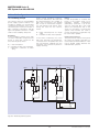
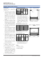
Figure 1 - Footprint 60/80kVA
Dimensions with packaging
50 cm between the top of the
cabinet and the roof
no wall-distance is required, unless
the cables are routed from above,
in which case the wall-distance
must be at least equal to the
bending radius of the cables in use.
The distance between covering
parts and floor is 150 mm.
no limits on either side of device
Rating (kVA)
Width
(mm)
60/80
810
100/120
1010
53
Ø 11
2000
1610
200
•
Height
(mm)*
50
1010
160
*
Depth
(mm)
Includes pallet.
Use a suitable lifting truck to
transport UPS and battery cabinets
to the storage or installation site on
the pallet in the original packaging.
The equipment must be kept
upright at all times and handled
with care, damage may be caused
if dropped or subjected to severe
impact.
When
moving
the
equipment with a forklift, secure it
against tilting.
Max. spacing for fork-lift bars (side)
UPS (kVA)
60/80
800
750
494
109
138
50
447
25
25
25
550
Figure 2 - Footprint - 100/120/160/
200kVA
100/120
max. (mm) 500
775
160
200
50
max. (mm) 1050
53
1175
Ø 11
Installation data
Refer to the User Handbook and the
Technical Data tables.
External dimensions - UPS
750
800
769 - 100/120 kVA
1044 - 160 kVA
1169 - 200 kVA
118.5
147
25
Rating
(kVA)
Width Depth + Front Height
(mm) (mm)1 panel 2 (mm)
(mm)
60/80
570
1400
100/120 845
160
1120
200
1245
1
2
50
722 - 100/120 kVA
997 - 160 kVA
1122 - 200 kVA
25
825 - 100/120 kVA
1100 - 160 kVA
1225 - 200 kVA
25
1675
858
1400
1780
1490
Including handle and front panel
- without handle: 830 mm
Space required to open front panel;
Front panel opens through 180°
Weight
•
•
•
•
60/80 kVA = 290 kg
100/120 kVA = 390 kg
160 kVA = 500 kg
200 kVA = 600 kg
21
MKA4CAT0UKD/Rev. 4-07/2008/UK
MASTERGUARD Series D
UPS Systems from 60 to 200 kVA
Appendix: Planning and Installation
UPS current ratings and cable cross sections
Description
UM
60
80
100
120
160
200
Iin max.
A
94
125
156
185
250
312
Suggested wire size(1)
mm2
35
50
70
95
120
2 x 70
Wire socket screw size
mm
M8
Inom OP/Res @400V
A
87
116
145
174
232
290
mm2
35
50
70
95
2 X 50
2 X 70
Wire socket screw size
mm
M8
Ibatt. in (disch. @1.8V/cell)
A
117
155
194
233
310
388
Suggested wire size
mm2
50
70
95
120
2 x 70
2 x 95
Wire socket screw size
mm
M10
70
Suggested wire
size(2)
Rating (kVA)
M10
M10
Suggested earth wire size
mm
35
50
Wire socket screw size
mm
M8
M10
2
95
In the case of a split bypass configuration, the primary input and bypass mains must have a common earth. The Neutral
conductor may be part of either the bypass or the primary mains, but it must be present.
1 With cable lug according to DIN46235.
2 For non-linear loads, the neutral cable dimension must be 1.7 times the recommended dimension.
Refer to the User Handbook for suggested IP/OP/BYP protection devices.
MKA4CAT0UKD/Rev. 4-07/2008/UK
22
MASTERGUARD Series D
UPS Systems from 60 to 200 kVA
Notes
23
MKA4CAT0UKD/Rev. 4-07/2008/UK
MASTERGUARD Series D
UPS Systems from 60 to 200 kVA
Notes
MKA4CAT0UKD/Rev. 4-07/2008/UK
24
Chloride Systems
WORLD HEADQUARTERS
Via Fornace 30
40023 Castel Guelfo (BO)
Italy
T +39 0542 632 111
F +39 0542 632 120
E [email protected]
For a full list of contacts please visit our website at www.chloridepower.com
MKA4CAT0UKD
www.chloridepower.com