1
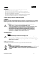
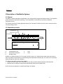
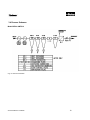
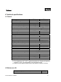
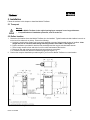
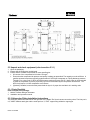
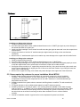
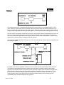
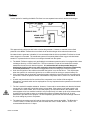
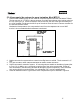
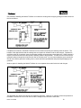
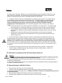
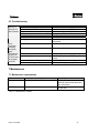
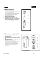
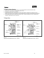
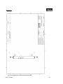
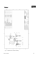
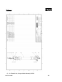
USER MANUAL
Mobile TireSaver
Parker Hannifin Corporation
Filtration and Separation Division
242 Neck Road, P.O. Box 8223
Haverhill, MA 01835-0723
U.S.A.
Tel: 800-343-4048 Fax: 978-858-0505
www.parkertiresaver.com
© 2005 Parker Hannifin Corporation, All rights reserved
26/10/2006 Bulletin TI-MTS06B
1
26/10/2006 Bulletin TI-MTS06B
2
Table of Contents
1 INTRODUCTION ..............................................................................................................................................4
1.1 GENERAL....................................................................................................................................................4
1.2 PICTOGRAMS IN THIS MANUAL ...................................................................................................................4
1.3 IDENTIFICATION AND SERVICE ...................................................................................................................5
1.4 USE IN ACCORDANCE WITH PURPOSE ..........................................................................................................5
1.5 USER INSTRUCTIONS...................................................................................................................................5
1.6 LIABILITY ...................................................................................................................................................6
2 HEALTH, SAFETY AND ENVIRONMENTAL ASPECTS..........................................................................6
2.1 GENERAL....................................................................................................................................................6
2.2 COMPRESSED AIR .......................................................................................................................................6
2.3 NITROGEN AND OXYGEN ............................................................................................................................6
2.4 SAFETY PRECAUTIONS ................................................................................................................................7
2.5 ENVIRONMENTAL ASPECTS.........................................................................................................................7
3 DESCRIPTION OF THE MOBILE SYSTEM ................................................................................................8
3.1 GENERAL....................................................................................................................................................8
3.2 SEPARATION PRINCIPLE ..............................................................................................................................8
3.3 PROCESS PARAMETERS ...............................................................................................................................9
3.4 PROCESS SCHEMES ...................................................................................................................................10
4 TECHNICAL SPECIFICATIONS .................................................................................................................11
4.1 GENERAL..................................................................................................................................................11
4.2 MAINTENANCE KITS .................................................................................................................................11
5 INSTALLATION..............................................................................................................................................12
5.1 TRANSPORT ..............................................................................................................................................12
5.2 DEFINE LOCATION ....................................................................................................................................12
5.3 UNPACK AND CHECK EQUIPMENT .............................................................................................................12
5.3.1 PARTS CHECKLIST .................................................................................................................................13
5.3.2 AFTERCOOLER FITTING INSTALLATION INSTRUCTIONS ..................................................................13
5.3.3 ITEMS REQUIRED BY CUSTOMER FOR PROPER INSTALLATION, MODEL MTS06............................14
5.3.4 ITEMS REQUIRED BY CUSTOMER FOR PROPER INSTALLATION, MODEL MTS12............................17
5.4 CONNECTION TO COMPRESSED AIR FEED AND NITROGEN CONSUMER .......................................................19
5.5 COMMISSIONING OF A MOBILE TIRESAVER ...............................................................................................19
5.6 ADJUSTING THE PURITY ............................................................................................................................20
6 OPERATION ....................................................................................................................................................20
6.1 START-UP OF TIRESAVER ..........................................................................................................................20
6.2 STOP OPERATION OF TIRESAVER ...............................................................................................................20
6.3 TROUBLE SHOOTING .................................................................................................................................21
7 MAINTENANCE..............................................................................................................................................21
7.1 MAINTENANCE REQUIREMENTS ................................................................................................................21
7.2 REPLACE FILTER ELEMENT .......................................................................................................................22
7.3 CLEAN AUTOMATIC DRAIN .......................................................................................................................22
7.4 REPLACE CARBON ADSORBER...................................................................................................................23
7.5 SPARE PARTS ............................................................................................................................................23
8 INDEX ...............................................................................................................................................................30
26/10/2006 Bulletin TI-MTS06B
3
1. Introduction
1.1 General
The Mobile TireSaver is a product of Parker Hannifin Corporation. This manual is an integral part of the product.
The manual describes the daily operation, maintenance required and troubleshooting techniques, if necessary.
Content
Read the manual carefully before you start with the Mobile TireSaver. Familiarize yourself with the content.
Condition of change
Only execute changes to the Mobile TireSaver after explicit prior written permission by Parker Hannifin. Nonconformance to this rule, as well as any consequential damage, loss and costs are the responsibility of the
owner and the user.
Information
All information in this manual, including additional drawings and technical descriptions, remains the property of
Parker Hannifin Corporation and may not be used (other than for the use of this product), copied, multiplied or
published to or for a third party without explicit prior written permission by Parker Hannifin Corporation.
1.2 Pictograms in this manual
In this manual the following pictograms are used:
Warning
A warning shows a hazard that can cause death or serious injury. Follow the
instructions.
Caution
A caution shows a danger that can cause damage to the equipment. Follow the
instructions.
Warning
Risk of death due to suffocation.
Risk of fire
Oxygen-enriched air leads to an increased risk of fire in the event of contact with
inflammable products.
High pressure risk
Follow the instructions with respect to compressed gasses.
Instructions with respect to the environment.
26/10/2006 Bulletin TI-MTS06B
4
1.3 Identification and service
The identification plate is located on
the left side of the Mobile TireSaver and
shows its characteristics.
For service and technical
assistance, please contact:
Parker Hannifin Corporation
Filtration and Separation Division
242 Neck Road, P.O. Box 8223
Haverhill, MA 01835-0723 USA
Tel
800-343-4048
Fax:
978-858-0625
www.parker.com/tiresaver
1.4 Use in accordance with purpose
The Mobile TireSaver nitrogen generator is intended to make nitrogen out of normal, compressed air. The system
is based on gas separation membrane technology. Each different or further use will not be in conformity with this
purpose. Parker will not accept any liability for improper use. The Mobile TireSaver nitrogen generator is in
compliance with the prevailing directives and standards. Only use this Mobile TireSaver in a technically perfect
condition, in conformity with the purpose as described above.
1.5 User instructions
Only properly trained personnel are allowed to work on the Mobile TireSaver nitrogen generator. The user must
be aware of hazards related to operating the Mobile TireSaver and processes connected to it. The user is
responsible for the safety of personnel nearby. All personnel working on the Mobile TireSaver must have free
access to the applicable manuals.
26/10/2006 Bulletin TI-MTS06B
5
1.6 Liability
Parker Hannifin Corporation will not accept any liability if (but not limited to):
o The instructions in this manual are ignored.
o Replacement parts are used which are not approved by the manufacturer.
o The system is operated incorrectly and not within recommended specifications.
o The system is fed with gasses other than air.
o The system is modified without notification and authorization of the manufacturer.
o Maintenance and repair are not carried out according to the instructions.
2 Health, safety and environmental aspects
2.1 General
Correct use of the Mobile TireSaver nitrogen generator is important for your personal safety and for trouble-free
operation. Incorrect use can cause damage to the Mobile TireSaver or can lead to incorrect gas supply to the
customer’s process.
Warning
o Read this manual before you start the installation and begin operation of the
Mobile TireSaver. Prevent accidents and damage to the system.
o Contact your supplier if you detect a problem that you cannot solve with this manual.
o Use the Mobile TireSaver in accordance with its purpose. Refer to section 1.4.
o Only service engineers that are qualified to work on pneumatic equipment are
allowed to do the installation, maintenance and repairs. Refer to section 1.5.
o Do not tamper or experiment with the equipment. Do not exceed the technical
specifications for the Mobile TireSaver. Refer to section 4.1.
2.2 Compressed air
Warning
o Ensure that the feed air pressure can not exceed 175 psig.
o Ensure that the equipment and the attendant piping is connected correctly for the
pressures required.
o Depressurize the Mobile TireSaver and the connected systems before you disconnec
parts of the system. The sudden escape of compressed air can cause serious injury or
damage. Refer to section 6.2.
2.3 Nitrogen and oxygen
The TireSaver generates nitrogen as a product. Oxygen enriched air is released as waste.
Warning
o Nitrogen can cause suffocation!
o Oxygen-enriched air leads to increased risk of fire in the event of contact with flammable
products. Make sure that there is adequate ventilation at all times!
o Do not install the Mobile TireSaver in an area where explosive substances may be
present.
26/10/2006 Bulletin TI-MTS06B
6
2.4 Safety precautions
Warning
o Ensure there is sufficient ventilation.
o Only feed the Mobile TireSaver with air.
o Maintain the air feed to the Mobile TireSaver clean and free of vapors of organic solvents
and other contaminants.
o Keep the ambient temperature between -30 and 110°F (up to 120°F for short periods of
time). Ensure the heat exchanger attached to the Mobile TireSaver is functioning
properly when the system is running.
o Install the peripheral equipment and piping according to all applicable local regulations.
Parker Hannifin Corporation is not responsible for customer installed piping.
o Regular maintenance should be performed on the Mobile TireSaver to ensure proper and
safe operation. Refer to chapter 7.
o Ensure that instructions concerning health and safety are compliant with local
regulations.
2.5 Environmental aspects
The use and maintenance of the Mobile TireSaver do not include environmental dangers. Most parts are made of
metal and can be disposed of in a manner consistent with local regulations.
o
Make sure that instructions concerning health, safety and environment are compliant
with all local regulations.
26/10/2006 Bulletin TI-MTS06B
7
3 Description of the Mobile System
3.1 General
The Mobile TireSaver separates compressed air into nitrogen and an oxygen enriched air stream. The separation
system is based on membrane technology. The compressed air is derived from a shared or dedicated
compressor source.
The nitrogen produced is usually dispensed directly from the Mobile TireSaver unit to the tire or may be stored in
a nitrogen storage vessel.
3.2 Separation principle
Separation layer
Support layer
B
Pressurized air
Nitrogen
C
A
H2 O, H2
O2
N2
S
F
Fig. 3-1: Separation principle
A
B
C
Pressurized air inlet
Hollow fiber membrane
Nitrogen outlet
F
S
Fast
Slow
Ambient air contains nitrogen (78.1%), oxygen (20.9%), argon (1%), carbon dioxide, water vapor and traces of
other inert gasses. Pressurized air (A) is fed through the hollow fiber membrane (B). The various air components
diffuse through the wall of the membrane.
The diffusion rate differs for the various gasses:
• Oxygen and water vapor have a high diffusion rate and permeate rapidly through the membrane wall.
• Nitrogen has a low diffusion rate and permeates slowly through the membrane wall.
At the exit of the membrane (C), pressurized nitrogen is released.
26/10/2006 Bulletin TI-MTS06B
8
3.3 Process parameters
The nitrogen production depends on these parameters:
Flow rate
The lower the flow rate of compressed air through the hollow fiber membrane, the more oxygen can permeate
through the membrane wall. As a result, the nitrogen produced at the outlet will have a higher purity. Nitrogen
purity can be adjusted with the flow control valve. This valve is factory preset; do NOT adjust without
consulting the factory first.
Temperature
The Mobile TireSaver operates optimally at a temperature between 70-80°F. If the temperature increases, the
pressurized air consumption will also increase. The system contains an integral heat exchanger to allow the gas
to cool before it enters the membrane.
Membrane pressure
A higher membrane pressure will increase the capacity (i.e. nitrogen output) of the Mobile TireSaver. Do not
exceed 175 PSIG. For ambient temperatures between 110°F and 120°F do not exceed 150 psig. Tire fill
times are directly related to inlet pressure. Fill times listed in literature are nominal, and assume full inlet pressure
(150 psig), minimal pressure drop through customer supplied fittings and adaptors from install, as well as clean
filters. Product will not work properly with an inlet pressure of less than 145 psig. Lower pressures will result
in longer fill times so it is important to maintain the system and the attendant compressor system. Also note any
fill times listed here or elsewhere are fill times only; they do not include the time it may take to drain a tire or to
perform multiple flushes.
External pressure
There must be atmospheric pressure at the vent or permeate outlet. The capacity and the purity of the nitrogen
gas decreases strongly if the vent or permeate pressure exceeds atmospheric pressure. Do not block off or
restrict the flow output of the permeate outlet.
Compressed Air Quality
Poor air quality (ie…oil, solvents, etc.) will affect performance and may permanently damage the nitrogen
membrane. Please see Section 4.1 for specifications.
26/10/2006 Bulletin TI-MTS06B
9
3.4 Process Schemes
Model MTS06 & MTS12
Fig. 3-4: Process Schematic
26/10/2006 Bulletin TI-MTS06B
10
4 Technical specifications
4.1 General
Delivery pressure
Maximum delivery pressure
MTS06
Inlet minus 10 psig
Compressed air requirements
Maximum feed pressure
Minimum feed pressure (2)
Compressed air temperature range
Residual oil content
Pressure dew point
Air Consumption
Electrical Requirements
Voltage
Current
Fuse Recommendation
MTS12
Inlet minus 20 psig
175 psig
145 psig
175 psig
145 psig
18 SCFM
40 to 250 °F
< 0.01 mg/m3
< 40 °F
35 SCFM
12VDC
6.5A
13A
15A
Ambient Conditions
Temperature (min/max)
High Temp. Climates (max) (1)
Dimensions and connections
Dimensions
Net Weight
Connections
-30 to 110°F
-30 to 120°F @ 150 PSIG
42.5”x28.7”x11.5”
200 lbs
Inlet
Outlet
Electrical
Output
Capacity at 68°F and 1 atm
Purity at specified capacity
42.5”x36.8”x11.5”
220 lbs
½“ NPT Female
½“ NPT Female
10” Wire leads
6 SCFM
12 SCFM
95% N2 by Volume
Table 4-1: General data
(1) For temperatures 110°F-120°F, regulate inlet pressure to 150 psig, with pressure
regulator (½“ NPT). Use intermittently in this temperature range.
(2) Product will not operate properly with an inlet pressure of less than 145 psig.
4.2 Maintenance Kit
Part
• MTS06 & MTS12 Maintenance Kit
26/10/2006 Bulletin TI-MTS06B
P/N
MKMTS
11
5. Installation
Follow the sections in this chapter to install the Mobile TireSaver.
5.1 Transport
Warning
o Put the Mobile TireSaver in the original packaging to transport it over longer distances.
o For qualifications of installation personnel, refer to section 2.1.
5.2 Define location
1. Determine the location where the Mobile TireSaver is to be installed. Typical locations include inside a box truck or
on the bed of a stake truck or pickup. Ensure the following:
a. Location is such that the system can be securely attached to prevent flying hazards in case of accident. Note
weight and size of unit when determining mounting location. See Table 4.1 and Figure 5.1
b. Proper ventilation is provided for both the heat exchanger and the oxygen enriched waste stream.
c. There is easy access to front and side of unit for routine maintenance and service.
d. Routing of inlet and outlet hose and electrical connections are convenient.
e. It must be mounted such that the unit stands upright (see Figure 5.1).
2. Perform the complete installation procedure again if you move the Mobile TireSaver to a new location.
Fig. 5-1: Location of Mounting Holes and Product Dimensions for MTS06
Bulletin TI-MTS06B
12
Fig. 5-2: Location of Mounting Holes and Product Dimensions for MTS12
5.3 Unpack and check equipment (refer to section 5.3.1)
1. Open the packaging.
2. Ensure that all components are delivered.
3. Ensure that the available compressed air meets specification:
• Oil content of the compressed air is below 0.01mg/m3.
• Ensure that the compressed air pressure and quality is always as prescribed. The capacity must be sufficient. A
gasoline powered compressor typically produces about 2 SCFM per horsepower at 175psig discharge pressure.
Therefore, for a duty cycle of 100% an MTS06 system needs a minimum of 9 HP. More power is recommended
to allow the compressor to have a proper duty cycle as recommended by the compressor manufacturer. The
MTS12 will require a 18 HP compressor at a minimum.
• [Optional] If installed, ensure that the pressurized air dryer is of proper size and that it is in working order.
5.3.1 Parts Checklist
Items included in the package:
1. Mobile TireSaver Nitrogen Generator.
2. Installation and operation manual.
5.3.2 Aftercooler Fitting Installation Instructions
The secondary AfterCooler mounted on the right side of the Mobile Tire Saver has two connection points. The inlet port is
a ½” MNPT stainless steel pipe and the outlet port is a ½” FNPT copper fitting welded to copper pipe.
Bulletin TI-MTS06B
13
Fig. 5-3: Installation of AfterCooler Fittings
Installing your fitting to the inlet port:
1. Follow normal pipe fitting practices.
2. Use Teflon tape, pipe dope or other suitable sealant/lubricant on the ½” MNPT pipe nipple to prevent damage to
the threads and allow for a tighter joint.
3. Install your fitting hand tight. Use of excess force will cause the pipe nipple to rotate and in turn the cooper tube to
rotate and kink.
4. Using a pipe wrench to hold the 1/2” stainless steel pipe nipple install your fitting per the manufacturers
instructions.
5. Never turn the ½” stainless steel nipple, as its rotation may cause damage to the copper tube of the AfterCooler.
Installing your fitting to the outlet port:
1. Follow normal pipe fitting practices.
2. Use Teflon tape, pipe dope or other suitable sealant/lubricant on your ½” MNPT fitting.
3. Install your fitting hand tight so it is snug but not too tight. Making sure the threads are aligned properly so as not
to strip the copper thread. Use of excess force will cause the cooper tube to rotate and kink.
4. Use a pipe wrench to hold the 1/2” copper fitting around the Hex only. Using tools other than a pipe wrench may
result in the tool slipping off of or stripping the hex. If this occurs the further rotation of your fitting will cause the
copper tube to rotate and kink.
5. Never turn the copper hex fitting, as its rotation may cause damage to the copper tube of the AfterCooler.
5.3.3 Items required by customer for proper installation, Model MTS06
1. Suitable means to attach process air from vehicle air compressor system to the inlet of the Mobile
TireSaver. The inlet connection is ½” FNPT (see section 4.1). Note that the inlet temperature of the
compressed air coming from the compressor can be over 200°F therefore it is recommended that high
temperature hose be used.
2. Suitable connection from system outlet to customer’s tire filling hoses or manifold. The exit connection is
½” FNPT.
3. PTFE pipe seal tape or other suitable thread sealant for the NPT thread connections.
4. Suitable connectors for mounting of system. 3/8” mounting holes are available on both sides of system
(refer to Figure 5.1). In addition, one or more bolts through the base of the unit are recommended. Either
new holes can be drilled in the base (being careful not to damage any system components) or some of
the drain holes can be utilized for mounting the bolts. Note orientation of unit: it must be installed
vertically.
5. Choose an installation method. A typical service truck compressed air system is as follows:
Bulletin TI-MTS06B
14
Fig. 5-4: Typical Service truck compressed air system schematic
On a typical service truck, a compressor would feed an air receiver which is on a pressure switch or relief
valve. When the upper pressure limit is reached, either the pressure switch will idle the compressor or the
relief valve will dump excess pressure from the air system. When demand exists the pressure in the receiver
will fall, and the compressor will start to generate again or the relief valve will close allowing pressure to build.
As hot air from the compressor travels down the air line it will cool down. Water condensate will form in the air
line if the compressed air temperature drops lower than the dew point of the compressed air. Therefore, a
drain valve is recommended at the bottom of the air receiver. Please check valve operation as part of routine
maintenance to ensure debris is not blocking the drain opening.
One method of installing the Mobile TireSaver is to utilize the existing hose reel(s) by placing three ball valves
into the line as follows:
Fig. 5-5: Three Valve Product Installation
If installed in this manner, the Mobile TireSaver can be turned on and off by the isolating valves as shown.
The benefits of this approach are that the existing hose reel system is utilized for both air and nitrogen.
Operation is as follows: when air is required, close the generator isolating valves and open the air ball valve.
When nitrogen is required, close the air ball valve and open the isolating valves to the generator. This will
force all of the air to the generator and put nitrogen back into the main line for the hose reels. It is not
recommended to open up both the air ball valve and the generator isolating valves; results would be
unpredictable and potentially damaging to the generator.
Bulletin TI-MTS06B
15
Another option for installing the Mobile TireSaver is to use separate hose reels for both air and nitrogen:
Fig. 5-6: Single Valve Product Installation
This approach only utilizes one ball valve to isolate the generator. However, to maintain correct feed
pressure to the Mobile TireSaver do not run both the air and the nitrogen hose reels at the same time.
No matter how the generator is installed, it is recommended that the inlet to the Mobile TireSaver be closed
when nitrogen is not needed. The membrane system will constantly bleed off the oxygen enriched waste
stream if it is pressurized even if there is no nitrogen demand from the system.
6. The Mobile TireSaver requires cool gas feeding the membrane system therefore it is equipped with a heat
exchanger driven by a 12VDC electric fan. The fan connection is a pair of wire leads which must be
attached to the service truck electrical system. It is advised that due to the potential danger of
distributing electric to this or any other system the electrical installation should be completed by
a licensed professional. There are three suggested means of hooking up the electrical system:
a. Hook into the ignition of the vehicle so that when the ignition is on, the fan will run. This requires that
when the system is in use that the ignition be on or that the truck be running to conserve battery life.
b. If the compressor has an electrically controlled pressure switch then the cooling fan for the system may
be tied into it. When the pressure switch is activated the compressor will run, and in turn, the fan will be
on.
c. A switch may be wired to the fan such that if the compressor is on, the fan will be energized.
Alternatively, a manual switch can be employed but it is very important that the operators turn the switch
on when in use.
7. The fan is sealed for weather resistance. However, if snow and ice accumulates such that the fan blade
cannot spin, the motor will lock causing a large current draw. If the system is not fused properly, this
condition will be a fire hazard. Even if it is fused properly, the fuse should blow in this instance. If the
motor appears to be in a condition in which it may not spin freely, let it warm up for a few minutes either
by pulling the truck inside to warm up or allowing the system to operate with the fan off. A quick
disconnect is provided for this purpose. The hot compressor gas will heat the heat exchanger tube and
fins, thus melting any snow or ice present.
8. The electrical connection must be fused as close to the power source as possible. The Blue wire is
+12VDC, black is -12VDC from the fan; the wire leads are: red is +12VDC, black is -12VDC. The
recommended fuse size is 15 Amps.
Bulletin TI-MTS06B
16
5.3.4 Items required by customer for proper installation, Model MTS12
1. Suitable means to attach process air from vehicle air compressor system to the inlet of the Mobile TireSaver.
The inlet connection is ½” FNPT; it is the top connector on the right heat exchanger (when looking at uint from
the fornt). See Figure 5.6. It will be necessary to connect hose from the outlet of the right heat exchanger to
the inlet of the Mobile TireSaver on the left side top of the cabinet Route this hose in a manner convenient for
the particular installation chosen.
Note that the inlet temperature of the compressed air coming from the compressor can be over 200°F
therefore it is recommended that high temperature hose be used.
Fig. 5-7: MTS12 Inlet Connection
2. Suitable connection from system outlet to customer’s tire filling hoses or manifold. The exit connection is ½”
FNPT.
3. PTFE pipe seal tape or other suitable thread sealant for the NPT thread connections.
4. Suitable connectors for mounting of system. 3/8” mounting holes are available on both sides of system (refer
to Figure 5.2). In addition, one or more bolts through the base of the unit are recommended. Either new
holes can be drilled in the base (being careful not to damage any system components) or some of the drain
holes can be utilized for mounting the bolts. Note orientation of unit: it must be installed vertically.
5. Choose an installation method. A typical service truck compressed air system is described in Figure 5-4.
Bulletin TI-MTS06B
17
One method of installing the Mobile TireSaver is to utilize the existing hose reel(s) by placing three ball valves into
the line as follows:
Fig. 5-8: MTS12 Three Valve Product Installation
If installed in this manner, the Mobile TireSaver can be turned on and off by the isolating valves as shown. The
benefits of this approach are that the existing hose reel system is utilized for both air and nitrogen. Operation is
as follows: when air is required, close the generator isolating valves and open the air ball valve. When nitrogen is
required, close the air ball valve and open the isolating valves to the generator. This will force all of the air to the
generator and put nitrogen back into the main line for the hose reels. It is not recommended to open up both the
air ball valve and the generator isolating valves; results would be unpredictable and potentially damaging to the
generator.
Another option for installing the Mobile TireSaver is to use separate hose reels for both air and nitrogen:
Fig. 5-9: MTS12 Single Valve Product Installation
This approach only utilizes one ball valve to isolate the generator. However, to maintain correct feed pressure to
the Mobile TireSaver do not run both the air and the nitrogen hose reels at the same time.
Bulletin TI-MTS06B
18
No matter how the generator is installed, it is recommended that the inlet to the Mobile TireSaver be closed
when nitrogen is not needed. The membrane system will constantly bleed off the oxygen enriched waste
stream if it is pressurized even if there is no nitrogen demand from the system.
6. The Mobile TireSaver requires cool gas feeding the membrane system therefore it is equipped with two
heat exchangers driven by two separate 12VDC electric fans. The fan connection is a pair of wire leads
which must be attached to the service truck electrical system. It is advised that due to the potential
danger of distributing electric to this or any other system the electrical installation should be
completed by a licensed professional. There are three suggested means of hooking up the electrical
system:
a. Hook into the ignition of the vehicle so that when the ignition is on, the fan will run. This requires that
when the system is in use that the ignition be on or that the truck be running to conserve battery life.
b. If the compressor has an electrically controlled pressure switch then the cooling fan for the system
may be tied into it. When the pressure switch is activated the compressor will run, and in turn, the fan
will be on.
c. A switch may be wired to the fan such that if the compressor is on, the fan will be energized.
Alternatively, a manual switch can be employed but it is very important that the operators turn the
switch on when in use.
7. The fans are sealed for weather resistance. However, if snow and ice accumulates such that the fan
blade cannot spin, the motor will lock causing a large current draw. If the system is not fused properly, this
condition will be a fire hazard. Even if it is fused properly, the fuse should blow in this instance. If the motor
appears to be in a condition in which it may not spin freely, let it warm up for a few minutes either by pulling
the truck inside to warm up or allowing the system to operate with the fan off. A quick disconnect is provided
for this purpose. The hot compressor gas will heat the heat exchanger tube and fins, thus melting any snow or
ice present.
8. The electrical connection must be fused as close to the power source as possible. The Blue wire is
+12VDC, black is -12VDC from the fan; the wire leads are: red is +12VDC, black is -12VDC. The
recommended fuse size is 15 Amps.
5.4 Connection to compressed air feed and nitrogen hose reel
Warning
o Make sure that the inlet and outlet hose and pipe are free of dust, particles, metal parts and curls,
liquids and grease before you connect the Mobile TireSaver.
1. Connect the product outlet to the hose reel connection or other process connection using pipe sealant or
PTFE tape for thread sealant.
2. Connect the compressed air supply to the compressed air inlet on the Mobile TireSaver using pipe sealant or
PTFE tape for sealing connections.
5.5 Commissioning of a Mobile TireSaver
1. Ensure that the connections are correct and tightened.
2. Check filter bowls and separator bowls for proper positioning, ensuring no leaks due to vibration.
3. Open the compressed air supply slowly – damage to membrane could occur if compressed air pressure is
not introduced slowly.
4. Ensure that the compressed air pressure comes up to full system output.
5. Ensure that the installation has no leaks which may have occurred due to transport.
Bulletin TI-MTS06B
19
6. The system is ready for use now.
7. Drain the condensate on a regular basis. It is recommended that this be done at least daily, if not more often.
Additionally, it is recommended that it be done while the system is under pressure and at the end of the work day to
prevent any condensate from freezing in cold climates. If no liquid is removed from drains in cold climates, the filter
bowls may have frozen condensate. Park truck in warm area until condensate thaws. Check filter bowls and
aftercooler fan area for ice, snow and water, as needed.
5.6 Adjusting the purity
The purity is factory pre-set at 95%, which means that there is 5% residual oxygen. The purity has been set by
adjusting the flow control valve. Normally the setting is stable and does not need to be checked.
If it becomes necessary to adjust the purity, this can be done by adjusting the flow control valve until the purity, as
measured with an oxygen analyzer taking a sample from the outlet, has the desired purity. As nitrogen purity is
increased, output flow will be reduced.
6 Operation
6.1 Start-up and operation of Mobile TireSaver
1. Open the compressed air supply very slowly and any outlet valve, if installed.
2. The system will start to produce nitrogen as soon as the nitrogen outlet is opened. The specified purity will be
available instantaneously.
3. It is highly recommended that the bowls of the separator and the two prefilters be drained after filling eight
truck tires or every hour of operation, whichever occurs first.
6.2 Stop operation of Mobile TireSaver
1. Shut off the pressurized air supply before you perform maintenance.
2. Depressurize the system by venting: use the condensate drains or open the nitrogen outlet until all pressurized gas
has vented.
TIP: should the filters not be fully depressurized it is possible to depressurize them
manually by slowly unscrewing the bleed screw on the bottom of the filter bowl on one of
the filters. Prior to reinstalling the bleed screw after venting, ensure the o-ring is seated
properly. It may be necessary to vent the filters all the way down to atmospheric pressure
so that the o-ring will seat.
Bulletin TI-MTS06B
20
6.3 Troubleshooting
Error
Delivery of
nitrogen too
low or absent
Possible cause
Compressed air supply too low
Ambient temperature is too high
Compressed air temperature is too high
Air filters are polluted
Leak in piping
Nitrogen outlet line is blocked
Blockage
Air is
constantly
escaping
from drain
ports
Fill times are
longer than
5-10 minutes
for a typical
truck tire
Pull drain is broken
Possible solution
Check/increase the air supply.
Lower the temperature, if possible.
Lower the temperature, if possible.
Change the air filters.
Check for leaks in piping; repair.
Check/open the outlet line.
Check the compressed air delivery from the
compressor.
Replace pull drain.
Pull drain is blocked
Open / close pull drain rapidly.
Low inlet pressure
Verify inlet pressure. See gauge on system.
Leaks in piping/hose
Generator flow is out of specification
Check for leaks downstream from generator;
correct.
Check with factory about setting.
Membrane is damaged
Check with factory about replacement.
7 Maintenance
7.1 Maintenance requirements
Part
Filter
Action
Replace filter element. Refer to section 7.2
Carbon Adsorber
Replace carbon. Refer to section 7.4
Frequency
2x per year, or when indicator on
the filter head reaches the end of
the indicator bar
Together with the filter elements,
2x per year
Table 7-1: Maintenance scheme
Bulletin TI-MTS06B
21
7.2 Replace filter element
1. Turn off the air supply.
2. Let the system depressurize.
3. Unscrew the bleed screw (E) slowly to ensure
that the filter is depressurized.
4. Turn the filter bowl (D) counter- clockwise and
pull the bowl from the filter housing (A).
5. Unscrew the blue knob (C).
6. Remove the old filter element (B).
7. Install a new filter element (B).
8. Assemble the parts in the reverse order.
9. When replacing part PS802, a small amount of
loctite is recommended on the threads of the
water separator locking ring for the bowl as the
bowl uses a threaded ring instead of a bayonet
type connector, as described here.
Fig. 7-2: Replace filter element
7.3 Clean automatic drain (if installed)
1. Open the filter by untwisting the bowl ¼ turn
counter-clockwise.
2. Unscrew the nut (F).
3. Remove the drain unit (B-E) from the filter bowl
(A).
4. Remove the O-ring (E).
5. Carefully pull the floating house (B) from the seat
(D). Do not bend the needle (C).
6. Clean the parts with soap and water. Make sure
that the needle bore is open and clean.
7. Assemble the parts in the opposite direction.
Make sure that the parts are dry before
reassembly.
Fig. 7-3: Clean drain filter
Bulletin TI-MTS06B
22
7.4 Replace Carbon Adsorber
1.
2.
3.
4.
Loosen and remove hose connectors from 37° JIC hoses attached to each end of carbon tower.
Remove four ¼-20 screws on clamps holding carbon tower.
Carefully pull carbon tower out of cabinet.
Install replacement tower; it will have the JIC elbows pre-installed. If adjustment is needed on the JIC
elbows, use a wrench to turn as needed. Be sure brackets are put into the correct place during re-assembly.
5. Screw carbon tower back into cabinet and reattach hoses. No pipe sealing tape or other compounds are
needed for reattaching the hose connectors.
7.5 Spare Parts
Fig. 7-4:
Replacement Parts/Maintenance Items – MTS06
Bulletin TI-MTS06B
Fig. 7-5:
Replacement Parts/Maintenance Items – MTS12
23
Fig. 7-6: Exploded View, Carbon Adsorber Assembly
Bulletin TI-MTS06B
24
Fig. 7-7: Exploded View, Filtration Assembly
Bulletin TI-MTS06B
25
Fig. 7-8: Exploded View, Nitrogen Module Assembly, MTS06
Bulletin TI-MTS06B
26
Fig. 7-9: Exploded View, Nitrogen Module Assembly, MTS12
Bulletin TI-MTS06B
27
Fig. 7-10: Exploded View, Mobile TireSaver Assembly, MTS06
Bulletin TI-MTS06B
28
Fig. 7-11: Exploded View, Mobile TireSaver Assembly, MTS12
Bulletin TI-MTS06B
29
8 Index
A
Ambient conditions, 11
Automatic drain, 22
C
Carbon element replacement, 22
Check equipment, 13
Clean automatic drain, 22
Commissioning, 19
Compressed air, 11
Connection, 19
D
Delivery pressure, 11
Dimensions, 11
E
Environmental aspects, 6
Error, 14
External pressure, 9
F
Filter element, 22
Flow rate, 9
I
Identification plate, 5
Installation, 12
Introduction, 4
L
Liability, 5
Location, 12
M
Maintenance, 21
Maintenance kits, 11
Membrane pressure, 9
Mounting dimensions, 11,12
N
Nitrogen, 6
O
Operation, 20
Output, 11
Oxygen, 6
P
Parts, 13
Possible cause, 21
Possible solution, 21
Process parameters, 9
Process schemes, 10
R
Replace carbon element, 23
Replace filter element, 22
S
Safety, 6
Safety precautions, 7
Separation principle, 8
Spare parts, 23-28
Start-up, 20
Stop, 20
T
Technical specifications, 11
Temperature, 9, 11
Transport, 12
Trouble shooting, 21
Bulletin TI-MTS06B
30
Parker Hannifin Corporation
Filtration and Separation Division
242 Neck Road, P.O. Box 8223
Haverhill, MA 01835-0723
Tel: 978-858-0505 Fax: 978-858-0625
Copyright ©Parker Hannifin Corporation 2006
Printed in U.S.A. TI-Bulletin MTS06B
31