1
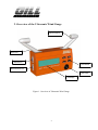
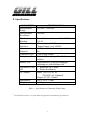
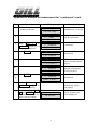
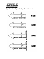
Ultrasonic Wind Gauge
User's Manual
Table of Contents
1. INTRODUCTION..............................................................................................................................................................1
2. OVERVIEW OF THE ULTRASONIC WIND GAUGE...............................................................................................2
3. SPECIFICATIONS ..........................................................................................................................................................3
4. POWER .............................................................................................................................................................................4
5. HANDLING & CAUTIONS............................................................................................................................................4
6. COMMUNICATION INTERFACES ............................................................................................................................4
6.1 REMOTE PORT ............................................................................................................................................................4
6.2 INPUT/OUTPUT PORT ................................................................................................................................................5
6.3 INTERFACE CONNECTION.............................................................................................................................................5
7. OPERATION MODES ....................................................................................................................................................6
7.1 AUTO CONTROL MODE................................................................................................................................................6
7.2 LOCAL CONTROL MODE..............................................................................................................................................7
APPENDIX A. EXAMPLE OF MEASUREMENT FOR “100M HURDLES” EVENT ..............................................9
APPENDIX B. EXAMPLE OF MEASUREMENT FOR “CONTINUOUS” EVENT................................................10
APPENDIX C. SETUP DIAGRAMS FOR PROPER DEVICE PLACEMENT ………............................................11
APPENDIX D. LYNX CONNECTION AND CONTACT INFORMATION ……….................................................12
APPENDIX E. TROUBLESHOOTING TIPS.............................. ...................………...................................................13
i
1. Introduction
Ultrasonic Wind Gauge (referred to as USWG in this text) is a one-axis
ultrasonic anemometer. The instruments measure the transit time of the
ultrasonic pulse between a pair of opposite ultrasonic transducers, in both
directions. From the measurements of tF and tB, the wind velocity component in
the direction of the two transducers can be calculated by the following equation:
V = D/2·(1/tF – 1/tB)
where:
D = distance between the two transducers
tF = forward transit time
tB = backward transit time
The main features of USWG are:
-Highly accurate and reliable wind velocity measurement
-LCD display of average wind velocity
-Continuous wind velocity reading
-Two communication interfaces: “REMOTE” and “INPUT/OUTPUT”
-Automatic interface to FinishLynx photo-finish system
-Remote starting option via cable
-Powered by 4 x AA size batteries or optional AC adaptor
-Automatic shut off for power saving
-Track and field sport wind velocity measurement
1
2. Overview of the Ultrasonic Wind Gauge
Ultrasonic Sensor
Sensor Arm
REMOTE Port
Control Buttons
INPUT/OUTPUT Port
Power Switch
LCD Display
Figure 1. Overview of Ultrasonic Wind Gauge
2
3. Specifications
PARAMETER
Measurement
Range
Measurement
Resolution
Wind velocity
Reading
Communication
Interfaces
Communication
Protocol
Connecter Type
Battery
Battery Life
Automatic Power
Off
AC adapter
Dimensions
Weight
SPECIFICATION
0.01 m/s - 20.00 m/s
0.01 m/s
Rounded in accordance with IAAF Rule
163.10
“Remote” port: RS232
“Input/Output” port : RS485
9600 Baud, 7 data bits, even parity, 1 stop
bit
9 pin D type female
4 x AA cells (rechargeable, alkaline or zinc
carbon)
Approximately 60 hours continuous
operating use with alkaline cells (1)
1. When idle for 2 hours
2. When dead battery
Input: 110/120V AC or
220/240V AC (Optional)
Output: 9V DC, 500mA
285 x 158 x 72 mm
0.66 Kg
Table 1. Specification of Ultrasonic Wind Gauge
(1)
Note that battery life may vary under different applications with different type of batteries.
3
4. Power
1. Four size AA batteries (rechargeable, alkaline or zinc carbon) are required.
2. Specified linear regulated AC adaptor (DC 9 volt, 500mA) provides an
optional power source in addition to batteries.
3. Mixed use of batteries of different chemical type is strictly prohibited.
4. USWG will shut off automatically if the system idles for over 2 hours. It is
suggested that user check up the system status after a long time duration of
no operation. If the system has been shut off, users have to turn off the
power switch to reset the system before turn it on again.
5. A message of “Battery Low !” will be displayed on the LCD panel when
the battery power is low. It is recommended to replace the batteries or use
AC adaptor if the “Battery Low !” message is displayed.
6. When the battery power is too low, USWG will shut off automatically to
prevent from over-discharge of the batteries.
7. The batteries should be removed before the gauge been put into storage.
5. Handling & Cautions
1. Sensor protection caps must be removed before use. When the system is not
in use, the sensor protection caps must be replaced.
2. USWG is a precision instrument. Do not touch or hammer or strike the two
arms of the instrument.
3. Carefully hold the body instead of the arms when handling the unit.
4. Do not use in raining or thunder-striking environment.
6. Communication Interfaces
USWG has two communication ports for automatic interaction with other
devices through direct connection. The two receptacles on the left side panel
labeled “REMOTE” and “INPUT/OUTPUT” provide the physical connection.
6.1 REMOTE port
A remote device connected to this port will receive wind velocity data
automatically at the end of each wind velocity measurement. The device must be
RS232 compatible and be programmed to receive the formatted data streams.
4
6.2 INPUT/OUTPUT port
A remote device connected to this port may both receive and send information
to and from the wind gauge via serial communication. The USWG may be
started, the time interval for wind velocity measurement may be set or reset, and
the most recent wind gauge measurement may be requested by the
communicating device.
6.3 Interface Connection
USWG communicates with a computer via the serial communication port
labeled INPUT/OUTPUT on the left side panel of the gauge. This serial
communication port has RS485 line drivers for long distance communication
(up to 450 m).
Computer interface connection instructions:
1. Plug the serial communication cable (9 pin D-Subminiature, male
connector) into the INPUT/OUTPUT connector on the left side of the
gauge.
2. The cable and connector pin connections for short distance
communication (L < 12 m) are as follows:
Ultrasonic
Wind Gauge
DB 9 pin
Male
Connector
Pin 3 TXPin 5 RXPin 6 RX+
Pin 7 TX+
DB 9 pin
Female
Connector
L
Pin 2 RX
Pin 3 TX
Pin 5 GND
RS232
(Connect pins 6 & 7)
FinishLynx
or PC
Figure 2. Short distance communication connection
3. Long distance communication (L > 12 m) requires an RS232 to RS485
converter to boost the computer or FinishLynx signal. The cable and
connector pin connections are as follows:
Ultrasonic
Wind Gauge
DB 9 pin
Male
Connector
L
Pin 3 TXPin 7 TX+
Pin 5 RXPin 6 RX+
RS485
RS232 to
RS485
Converter
RS232
Cable with Terminators
FinishLynx
or PC
Figure 3. Long distance communication connection
4. Configure the computer for transmission as follows: Baud Rate = 9600;
Data Bits=7; Parity=Even; Stop Bits=1.
5
7. Operation Modes
USWG can be operated manually or automatically via a remote computer.
Two operation modes are defined:
1. Auto Control Mode: a remote computer controls the wind velocity
measurement through RS485 serial communication interface.
2. Local Control Mode: users operate the wind velocity measurement by using
the four control buttons on the front panel or the remote starting cable.
7.1 Auto Control Mode
For Auto Control mode, a remote computer with FinishLynx software controls
the wind velocity measurement through RS485 serial communication interface.
While the gauge goes into Auto Control mode, an “auto” string followed by the
measure interval will be displayed on LCD panel. At this moment, the four
control buttons on front panel and the remote start button won’t respond until the
Auto Control mode exits.
The priority of Auto Control mode command is higher than Local Control
mode operation. Once the two operations conflict, the Auto Control mode
command will be executed. Nevertheless, mixing use of Local Control operation
with Auto Control operation is prohibited.
7.1.1 Command format for Auto Control
<0x01><0x13>CW<opcode><0x02><data><0x04>
<opcode> = R | S | I | O
<data>
= <digit><digit>
<digit>
= 0|1|2|3|4|5|6|7|8|9
Opcode :
R – Reset.
<data> = nothing, send ‘00’
S – Start. Begin taking a wind reading.
<data> = nothing, send ‘00’
I – Interval. Set the length of the next reading.
<data> = number of seconds
O – Output. Send the most recent reading.
<data> = nothing, send ‘00’
6
7.1.2 Data format for Auto Control
<0x01><0x13>GW<0x02><0x10>0013<reading><0x04>
<reading> = <sign><digit><digit>.<digit><digit>
<sign>
= +|<digit>
= 0|1|2|3|4|5|6|7|8|9
7.2 Local Control Mode
The default operation mode when powered on is Local Control mode. In
Local Control mode, users may change the event setting by pressing ROLL↓
and ROLL↑ buttons, and start/reset the wind velocity measurement by pressing
the START and RESET buttons. Users also can control the start/reset action in
Local Control mode by pressing the remote start button if the remote starting
cable is attached to the “REMOTE” port. The last event setting of Local Control
mode will be stored in the EEPROM memory of the gauge, and will be recalled
when next time powered on.
The function definitions of the control buttons is listed in Table 2. The
configuration of LCD display for Local Control mode is depicted in Figure 4.
Table 3 lists all events for Local Control mode, in which the 8th event , ”last
result”, is used for recall the most recent wind velocity menasrement reading.
The time duration of wind velocity measurement for various event is listed in
Table 4. For a detail operation of wind velocity measurement under various
event, please refer to Appendix A and B.
Button caption
ROLL↓
Function description when pressed
Select next event item
ROLL↑
Select previous event item
START
RESET
Start countdown timer to take a wind velocity measurement
Reset countdown timer to prepare for measurement
Table 2. Button function definitions for Local Control mode
7
Upper line is for event indication and low battery
warning.
Lower line is for wind velocity, or countdown timer /
next action.
Figure 4.
LCD display configuration for Local Control mode
No.
1
2
3
4
5
6
7
8
Table 3.
1>
2>
3>
4>
5>
6>
7>
8>
Event Menu
100m
200m
100m hurdles
110m hurdles
long jump
triple jump
continuous
last result
Event list for Local Control mode
Event
100m
200m
100m hurdles
110m hurdles
long jump
triple jump
continuous
Table 4.
Interval
10 sec
10 sec
13 sec
13 sec
5 sec
5 sec
1 sec
Time duration of wind velocity measurement for various event
8
Appendix A. Example of measurement for “100m hurdles” event
Step
1
Operation
Press power switch “ 1
“ to turn on the unit
2
LCD Display
GILL ATHLETICS
US Wind Gauge
1>
100m
Description
Display product
information for 3 seconds
Display last event setting,
ready for operation
START or ROLL ?
3
4
Press ROLL ↓
or
ROLL ↑ button to set
event as “100m hurdles”
3> 100m hurdles
START or ROLL ?
Press START button
3> 100m hurdles
13 sec or RESET ?
5-a
If necessary, press
RESET button before
timer count down to zero
to stop measurement
5-b
6-a
or
Press RESET button
6-b
or
Press START button
6-c
7
Select event setting as
“100m hurdles ”
The timer starts to count
down from 13 seconds to
zero
START or ROLL ?
The countdown timer is
reset and the
measurement is aborted
3> 100m hurdles
+01.50 m/sec
Measured wind velocity
will be displayed at the
end of countdown
3> 100m hurdles
Prepare for next wind
velocity measurement
3> 100m hurdles
START or ROLL ?
3> 100m hurdles
13 sec or RESET ?
Start another wind
velocity measurement
Press ROLL ↓
or
ROLL ↑
button to
change event setting
If necessary, press ROLL
↓ or ROLL ↑ button
to event 8 to recall last
wind velocity reading
8> last result
+01.50 m/sec
9
The most recent wind
velocity measurement
will be displayed
Appendix B. Example of measurement for “continuous” event
Step
1
Operation
Press power switch “ 1
“ to turn on the unit
2
3
4-a
LCD Display
GILL ATHLETICS
US Wind Gauge
1> 100m
START or ROLL ?
Press ROLL ↓
or
ROLL ↑ button to set
event as “continuous ”
Press START button
7> continuous
Description
Display product
information for 3 seconds
Display last event setting,
ready for operation
Select event setting as
“ continuous ”
START or ROLL ?
7> continuous
Starts wind velocity
measurement
1 sec or RESET
4-b
7> continuous
* 1 sec or RESET
4-c
7> continuous
* +01.50 m/sec
5-a
or
5-b
6
Press RESET button
7> continuous
A flashing * mark
indicates measurement is
going on
Wind velocity is
displayed and updated
for every second
Stop wind velocity
measurement
START or ROLL ?
Press ROLL ↓
or
ROLL ↑
button to
change event setting
If necessary, press ROLL
↓ or ROLL ↑ button
to event 8 to recall last
wind velocity reading
Stop wind velocity
measurement, select
event setting
8> last result
+01.50 m/sec
10
The most recent wind
velocity measurement
will be displayed
Appendix C. Setup Diagrams For Proper Device Placement
11
Appendix D. Lynx connection and Contact Information
Gill Wind Gauge Cable
Computer End
Wind Gauge End
DB9 Female
DB9 Male
Pin 2 --------------------------------------------------------------------------------- Pin 3
Pin 3 --------------------------------------------------------------------------------- Pin 5
Pin 5 --------------------------------------------------------------------------------- Pin 6
Pin7 (add jumper wire
between 6 + 7)
Lynx System Developers, Inc.
179 Ward Hill Ave
Haverhill, MA 01835
(tel)978-556-9780
(fax)978-556-9781
www.finishlynx.com
12
Appendix E. Troubleshooting
Check internal connections.
If your wind gauge suddenly stops working, take off the back panel and check
to see that the connections haven’t come loose. If they have, simply put them
back on and replace the back panel.
13


![English [2012v1]](http://vs1.manualzilla.com/store/data/005666127_1-015c2c1b906ab908850f1f1f8721a849-150x150.png)