1
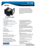
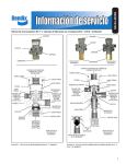
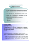
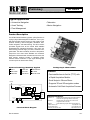
RF8009
Preliminary
0
GLOBAL POSITIONING SYSTEM RECEIVER
Typical Applications
• Automotive Navigation
• Telematics
• Asset Tracking
• Marine Navigation
• Fleet Management
Product Description
The RFMD Global Positioning System (GPS) Receiver is
a plug-n-play module designed for OEM use. The 12-parallel-channel GPS receiver works in a wide variety of end
products including: marine navigation, telematics, automotive navigation, and asset tracking. The GPS receiver
processes signals from all the visible GPS satellites
broadcasting RF navigation information. “All-in-view” satellite tracking produces highly accurate, smoothed navigation data. The data is relatively immune to the position
jumps that occur when fewer satellites are monitored.
Designed to withstand harsh industrial environments, the
GPS receiver performs robustly in situations where
extreme vehicle movement or high signal blockage are
concerns (such as dense urban areas).
Optimum Technology Matching® Applied
Si BJT
GaAs HBT
Si Bi-CMOS
SiGe HBT
InGaP/HBT
GaN HEMT
Package Style: 38mmx38mm
GaAs MESFET
9Si CMOS
9SiGe Bi-CMOS
Features
• Fast satellite time-to-first-fix (TTFF) with
a Rapid Acquisition Module
• Small footprint: 38mmx38mm
GPS Antenna
(26 dB Gain)
• Supports 3D and 2D navigation modes
• Automatic Cold Start Acquisition Process
L1 BP Filter
RTC Crystal
(32 kHz)
LNA
RTC
FLASH
Temp.
Sensor
I/O
Connector
Filter
Gain
Osc.
RF ASIC
Digital
ASIC
Supervisor
+2.5 V
Reg.
GPS Crystal
(43 kHz)
Low Noise Amplifier
ADC
Digital ASIC
Functional Block Diagram
Rev A0 030723
1. +3.3 V
2. GND
3. TX1
4. RX1
5. T-Mark
6. V_Antenna
7. +2.5 V Battery
8. RX2
9. TX2
10. GPIO20
Ordering Information
RF8009-1
Global Positioning System Receiver (with straight I/O
connector and right angle MCX RF connector)
RF8009-2
GPS Receiver (with straight I/O connector and
straight MCX RF connector)
DK8009
Global Positioning System Receiver Evaluation Kit
RF Micro Devices, Inc.
Tel (336) 664 1233
7628 Thorndike Road
Fax (336) 664 0454
Greensboro, NC 27409, USA
http://www.rfmd.com
14-1
RF8009
Preliminary
Absolute Maximum Ratings
Parameter
Rating
Unit
Supply Current
RF Input Level
Operating Ambient Temperature
Storage Temperature
210
-20
-40 to +85
-40 to +85
mA
dBm
°C
°C
Parameter
Specification
Min.
Typ.
Max.
Caution! ESD sensitive device.
RF Micro Devices believes the furnished information is correct and accurate
at the time of this printing. However, RF Micro Devices reserves the right to
make changes to its products without notice. RF Micro Devices does not
assume responsibility for the use of the described product(s).
Unit
Condition
External Power
Requirements1
Voltage
3.17
1.65
3.3
2.5
3.43
2.7
VDC
VDC
Operate mode
Battery backup mode
410
145
mW
mW
1 second updates
40
mW
6
µA
mV
5 minute updates2
Battery backup mode
Operate mode
Battery backup mode
Power Consumption
Ripple Peak-to-Peak
100
N/A
1 minute updates2
Signal Acquisition
Performance
Accuracy
Horizontal
Vertical
Velocity
DGPS
Solution Update Rate
Time Mark
Serial Data Output Protocol
Serial Ports
Primary Port
Auxiliary Port
5.8
9.7
0.06
<1
1
1
m
m
m/s
m
sec
sec
2d RMS
2d RMS
1 Sigma
2d RMS
19,200
9600
bps
bps
Binary, no parity, 8 data bits, 1 stop bit
RTCM SC-104, no parity, 8 data bits, 1 stop
bit
1575
3
2.5
MHz
dBic
dB
MHz
dB
50
mA
1s±100ns (1Sigma)
Binary, NMEA-0183
Antenna Requirements
Frequency
Antenna Gain
Amplifier Gain
Amplifier Filter Noise Bandwidth
Noise Figure
Connector Type
Amplifier Voltage, 3VDC to 5VDC
26
20
At 90° elevation
Including cable loss
At the 3dB points
MCX
Supplied by OEM
RF Signal Environment
RF Input Frequency
RF Input Power
Sensitivity
1575.42
31
-113
MHz
dB-Hz
dBm
L1 frequency band
Costas threshold
1
Power must be within the specified limits within 40ms after power turn-on.
2Results
with Power Management software using external hardware control.
This datasheet is for Software version 4.7.0 or later.
14-2
Rev A0 030723
RF8009
Preliminary
Parameter
Specification
Min.
Typ.
Max.
Unit
Condition
Environmental
Requirements
Cooling
(Operating/Storage)
Temperature
(Operating/Storage)
Humidity
Altitude
Maximum Vehicle Dynamic
Free air
convection
-40
-1000
Jerk
5
Acceleration
4
Rev A0 030723
+85
°C
95
%
+60,000
515
ft
m/s
Relative humidity up to 95% non-condensing
or a wet-bulb temperature of +35°C, whichever is less.
Acquisition and navigation
(meters per second)
m/s3
G
14-3
RF8009
Preliminary
Package Style
Module - 38mmx38mm
RF8009-1 (right angle MCX RF connector configuration)
5.20
2.00
O 2.54
4 PLACES
10
38.00
32.42
28.32
20.38
4.11
1.57
4.56
1
2.79
2.79
0.22
5.74
2.20
24.55
32.42
38.00
RF8009-2 (straight MCX RF connector configuration)
O 2.54
4 PLACES
10
38.00
32.42
28.32
20.38
4.11
1.57
6.22
1.93
1
2.79
2.79
24.55
32.42
38.00
14-4
Rev A0 030723
RF8009
Preliminary
I/O Connector Detail
(Samtec part number: TMMH-104-01-F-D)
(2,00)
0.0787
B
A
C
LEAD
STYLE
-01
Rev A0 030723
A
B
C
(7,67) (3,20) (2,46)
0.302 0.126 0.097
14-5
RF8009
Preliminary
Theory of Operation
The RFMD GPS receiver is a single-board, 12 parallel-channel engine designed for OEM use. The GPS receiver processes signals from the visible GPS satellites broadcasting RF navigation information. “All-in-view” satellite tracking produces highly accurate, smoothed navigation data. The data is relatively immune to the position jumps that occur when
fewer satellites are monitored. Designed to withstand harsh industrial environments, the GPS receiver performs robustly
in situation (such as dense urban areas) where extreme vehicle movement or high signal blockage are concerns.
When fewer than four satellites are available or when operating conditions require, the GPS receiver supports 2D navigation. To calculate a fix while in 2D navigation mode, the receiver uses either the last altitude determined while in 3D navigation mode, or data supplied by the user.
Satellite acquisition can be obtained under most initialization situations, as long as the receiver can “see” the satellites.
Rapid time to first fix (TTFF) is a feature of the Rapid Search Engine. The flexible satellite acquisition system takes
advantage of all available information to provide rapid TTFF, even without user initialization. To minimize TTFF when primary power is removed from the receiver, a DC supply voltage maintains the real time clock (RTC). This allows the GPS
receiver to use the prior position data and satellite information stored in the GPS receiver’s flash memory.
The receiver has two independent, asynchronous serial input/output ports. The receiver’s primary serial port outputs
navigation data and accepts commands in the NMEA-0183 or binary message formats. The receiver’s secondary serial
port accepts differential GPS (DGPS) corrections in RTCM SC-104 format. See the “Message Definitions” section for
more information.
Receiver Architecture
The GPS receiver chipset includes all the radio frequency (RF) direct sampling and amplification circuitry. These circuits
present both the sign and magnitude of sampled data to the digital ASIC. The digital ASIC contains an integral microprocessor (PowerPCR 401), the GPS signal processing, SRAM, and the RTC. Memory and other supporting components
are needed to make a complete navigation system.
Receiver Operation
The receiver requires 3.3V DC primary input power.
The receiver’s antenna must have visibility of the sky in order to acquire enough satellites to produce a navigation solution. While this is usually not a problem outdoors, operation indoors or in a vehicle may require that the antenna be
located with an unobstructed view of the sky. If the satellites are blocked from the receiver’s antenna, the receiver will
take longer to acquire a position. If fewer than four satellites are available, the receiver may be able to determine a valid
2D position solution by using altitude aiding.
Signal Acquisition Modes
The GPS receiver supports the following four signal acquisition modes, depending on the availability of critical data.
Cold Start
Warm Start
Hot Start
Reacquisition
14-6
In this mode, the receiver has valid almanac and frequency standard parameters available in memory.
The receiver enters this mode on start-up when battery back-up power is not maintained.
In this mode, the receiver has the following valid data either available in memory or provided by the
user at initialization: position, time, almanac, and frequency standard parameters. The receiver enters
this mode following a long power-off cycle (greater than a few hours) when battery back-up power is
maintained.
In this mode, the receiver has the following valid data available in memory: position, velocity, time,
ephemeris, almanac, and frequency standard parameters. The receiver enters this mode following a
software reset or on short power-off cycles (less than a few hours) when battery back-up power is
maintained.
In this mode, the receiver has experienced a signal blockage for a short period of time (less than
10seconds) that was preceded by a period of continuous navigation.
Rev A0 030723
RF8009
Preliminary
Table 1 (below) indicates the time to first fix (TTFF) when operating in each of the signal acquisition modes.
Table 1. Signal Acquisition Mode Performance
Acquisition Mode
TTFF1,2
(seconds)
Initial Position Tolerance (3 Sigma)
Position
Velocity
Time
(km)
(m/sec.)
(minutes)
Cold Start
44
Warm Start
40
N/A3
100
N/A3
75
N/A3
5
Hot Start
Reacquisition
10
1
100
100
75
75
5
5
1Typical
Maximum
Maximum
Almanac Age Ephemeris Age
(weeks)
(hours)
1
N/A3
1
N/A3
1
1
4
4
values.
2
Times given are valid at 25°C with no signal blockage.
3
Not available in real time to the receiver.
Navigation Modes
The GPS receiver supports three navigation modes: three-dimensional (3D), two-dimensional (2D) and Differential GPS
(DGPS).
When four or more satellites are available with good geometry, the receiver enters the 3D navigation mode.
When fewer than four GPS satellites are available, or when a fixed altitude can be used to produce an acceptable result,
the GPS receiver enters the 2D navigation mode. To calculate a fix in 2D navigation mode, the receiver uses either the
last altitude determined in 3D navigation mode or data supplied by the user. In 2D navigation, navigational accuracy is
primarily determined by the relationship of the fixed value of altitude to the true altitude of the antenna.
When four or more satellites are available with differential corrections, the receiver enters the DGPS navigation mode.
Accuracy is a function of the entire GPS system, including the geometry of the satellites at the time of measurement.
Individual GPS receivers have very little influence over position accuracy. Navigational accuracies are provided in Table
2.
Table 2. Navigational Accuracy
Position (2drms, 95% All-in-View)
Horizontal
Vertical
5.8m
9.7m
Velocity
0.06 m/s
DGPS
<1m
Time
100ns
Power Modes
The GPS receiver has the following three power modes.
Off Mode
Operate Mode
Battery Back-up
Mode
The receiver is completely de-energized at all DC supplies, input signals and control signals.
The receiver operates normally when an external DC supply is connected to the receiver’s primary
input terminal, V3_3P.
The receiver enters battery back-up mode when the primary input power voltage is removed, provided an external DC supply is connected to the RTC terminal, V2_5BU. If the receiver is powered
up in this mode, it uses the current time from the RTC and critical satellite data stored in flash memory to achieve rapid TTFF.
Electrical Requirements
The host system supplies power as specified in the parameter table.
Rev A0 030723
14-7
RF8009
Preliminary
Antenna Power
The GPS receiver passes the voltage applied to the V_ANT pin on the I/O connector to the center conductor of the RF
connector. The voltage to V_ANT can be either positive or negative and can range up to 15VDC.
NOTE: No form of current limiting is provided, and damage to the board may result if the RF center conductor is shorted
to ground. Antenna preamp, pass-through current must be limited outside the receiver.
Antenna Sense Circuit (Optional Feature)
The optional antenna sense feature is useful for verifying the proper connection to the GPS antenna. With this feature
implemented, the GPS receiver is capable of detecting antenna undercurrent and overcurrent conditions. The antenna
sense status can be requested using the IBIT message and the results will be reported in the OBIT message.
NOTE: If the optional antenna sense circuit is used, the voltage to the V_ANT pin on the GPS receiver connector may
either be +3.3V or 5VDC, depending on the specific antenna requirements. DC current is limited on the board to approximately 100mA.
Input/Output Signals
Signals are listed by pin number and described in Table 3. All digital I/O signals are 2.5VDC CMOS buffered signal levels,
tolerant of 3.3VDC.
Table 3. Input/Output Connections
Pin
Number
1
2
3
Signal
Name
V3_3P
GND
TX1
4
RX1
5
TMARK
6
7
V_ANT
V2_5BU
8
RX2
9
10
TX2
GPIO20
14-8
Description
Main power input to the receiver. Input power requirements are defined in Table 3.
DC ground to the receiver.
Primary asynchronous full-duplex serial data port transmit (TX) line. Binary and NMEA message protocols are supported. The default settings are:
Message format
Binary
Baud
19200bps
Parity
None
Data Bits
8
Stop Bit
1
For additional information, see the GPS receiver evaluation kit user manual.
Primary asynchronous full-duplex serial data port receive (RX) line. Binary and NMEA message
protocols are supported. The default settings are:
Message format
Binary
Baud
19200bps
Parity
None
Data Bits
8
Stop Bit
1
For additional information, see the GPS receiver evaluation kit user manual.
UTC time-mark pulse, one pulse per second. The Binary message OTMP contains the UTC
time associated with the time-mark pulse.
Provides a power connection to the center conductor of the RF connector.
Provides a back-up power connection for the receiver’s real time clock (RTC). Input power
requirements are defined in Table 3.
Auxiliary asynchronous full-duplex serial data port receive (RX) line. DGPS RTCM SC-104 message protocol is supported. The default settings are:
Message format
RTCM SC-104
Baud
9600
Parity
None
Data Bits
8
Stop Bit
1
For additional information, see the GPS receiver evaluation kit user manual.
Auxiliary asynchronous full-duplex serial data port transmit (TX) line.
General purpose input/output.
Rev A0 030723
RF8009
Preliminary
Message Definitions
The following Binary and NMEA message definitions are provided in the RFMD GPS Receiver User Manual (available
with purchase of the GPS Receiver Evaluation Kit). Contact RFMD customer service for more information.
Table 4. Binary Output Messages
Binary
Message
ONVD
OSAT
OCHS
ODGS
ODGC
ONOC
ONVC
ONPC
OCSC
OEMA
ODTM
ODTU
OTMP
OALD
OEPD
OUTD
OSHM
OSID
OBIT
OFSH
Description
Navigation Solution Data
Visible Satellites
Channel Status
DGPS Status
DGPS Configuration
Navigation Operational Configuration
Navigation Validity Configuration
Navigation Platform Configuration
Cold Start Configuration
Elevation Mask Angle Configuration
Map Datum Select
User Datum Definition
UTC Time Mark Pulse
Download Almanac Data
Download Ephemeris Data
Download UTC/IONO Data
Satellite Health Masking Configuration
Receiver Software ID
Built-in-Test Results (ACK)
Command Flash Upload (ACK)
Default On
Yes
On update
Yes
No
No
Once at Power-Up/Reset
Once at Power-Up/Reset
No
Once at Power-Up/Reset
Once at Power-Up/Reset
Once at Power-Up/Reset
No
Yes
No
No
No
No
Once at Power-Up/Reset
No
No
Table 5. Binary Input Messages
Binary
Message
INIT
IDGC
INOC
INVC
INPC
ICSC
IEMA
IDTM
IDTU
IALD
IEPD
IUTD
ISHM
IRST
IFSH
ILOG
IIOC
IMPC
IBIT
Rev A0 030723
Description
Navigation Initialization
DGPS Configuration
Navigation Operational Configuration
Navigation Validity Configuration
Navigation Platform Configuration
Cold Start Configuration
Elevation Mask Angle Configuration
Map Datum Select
User Datum Definition
Command Almanac Upload
Command Ephemeris Upload
Command UTC/IONO upload
Satellite Heal Masking Configuration
Command Reset
Command Flash Upload
Message Log Control
Input/Output Port Configuration
Message Protocol Configuration
Command Built-in-Test
14-9
RF8009
Preliminary
Table 6. NMEA Output Messages
NMEA
Message
SID
GGA
GLL
GSA
GSV
RMC
VTG
BTO
CHS
Description
Software Version
GPS Fix Data
Geographic Position: Latitude/Longitude
GPS DOP and Active Satellites
GPS Satellites in View
Recommended Minimum Specific GPS/Transit Data
Track Made Good and Ground Speed
Built-in-Test Results (ACK)
Channel Status Data
Default On
Once at Power-Up/Reset
Yes
No
Yes
On Update
Yes
No
No
Yes
Table 7. NMEA Input Messages
NMEA
Message
INT
LOG
IOC
MPC
RST
BTI
Description
Receiver Initialization
Message Log Control
Input/Output Port Configuration
Message Protocol Configuration
Command Reset
Command Built-in-Test Required
Table 8. RTCM SC-104 Messages
RTCM
Message
Type 1
Type 2
Type 9
14-10
Description
Differential GPS Corrections
Delta Differential GPS Corrections
Partial Satellite Set Differential Corrections
Rev A0 030723