1
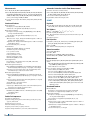
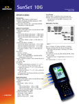
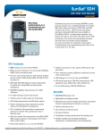
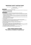
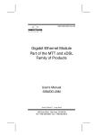
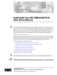
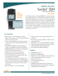
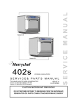
supplied and supported in the UK & Ireland by Phoenix Datacom - tel: 01296 397711 - [email protected] - www.phoenixdatacom.com STT ONE ® OTN and Next-Generation SDH/SONET Testing The STT Optical Network Expert (ONE) is a powerful and versatile test module for the Scalable Test Toolkit (STT) for testing emerging technologies such as OTN (ITU-T G.709) and next-generation SDH/SONET, as well as traditional SDH/SONET, offering service providers a complete solution for today’s metro and core networks. By integrating OTN and EoS (VCAT, GFP, and LCAS) testing into a single, compact unit, the STT ONE module is extremely cost effective because it eliminates the need for multiple instruments. The STT ONE is part of a family of test modules for the STT Platform KEY Features • OTN, EoS, SDH, SONET in one instrument • Dual wavelength optical transmitters up to 2.66 Gbps • Advanced differential delay measurement, generation, and payload reassembly • Fully independent or can be combined with other test modules to enhance application • Ethernet traffic generation over SDH/SONET without extra equipment • • • • • • • • Auto-configuration and Channel Master With the growth of IP services and the increasing need to leverage existing SDH/SONET networks, service providers must routinely monitor and test NGN to ensure packet-based traffic is properly delivered across the network. STT ONE offers a complete solution for NGN. Benefits • • • • • All-in-one test solution Single, compact unit Extremely cost-effective Eliminates the need for multiple instruments Intuitive user-friendly GUI OTU1 (2.66 Gbps) and OTU2 (10.7 Gbps) interfaces ODU Time Division Multiplexing (ODU1 into OPU2) Synchronous/asynchronous mapping of SDH/SONET signals OTN/SDH, OTN/SONET mux test Error performance analysis per ITU-T G.8201 and M.2401 OTU, ODU, OPU error injection & alarm generation OTU, ODU, and OPU bytes control and decode Next-Generation SDH/SONET In addition, high and low order virtual concatenation capabilities help verify end-to-end connectivity. Its differential delay detection and generation functions help measure the delay in the existing network and stress the far end payload assembly circuitry. Test features Virtual Concatenation (VCAT ) The ST T ONE allows the user to perform routine and advanced testing on transport and access networks, legacy and next-generation networks with a single test set. Its price to performance ratio makes this product ideal. • SDH/SONET error performance analysis per ITU-T G.821, G.828, G.829, M.2101, M.2110, M.2120, and Telcordia GR-253 Optical Transport Network (OTN) STT ONE provides Forward Error Correction (FEC), verifies conformance to ITU-T G.709 and a wide range of network performance standards, including end-to-end connectivity at OTU1 and OTU2 bit rates, and complete synchronous/asynchronous mapping of SDH/SONET client signals. • Conforms to ITU-T G.707, Telcordia GR-253 & ANSI T1.105-2001 • Virtual Concatenation Testing, VC-4-X-v, VC-3-X-v, VC-12X-v, VC-11-X-v / STS-3-X-v, STS-1-X-v, VT1.5-X-v, VT2-X-v • Differential delay generation, measurement, and payload reassembly up to 256 ms • Path overhead bytes control and decode on each member • Error injection/alarm generation on each member Generic Framing Procedure (GFP) • • • • Conforms to ITU-T G.7041 and ANSI T1.105-2001 GFP-F, GFP-T support GFP header control, error injection, and error detection Mapping/demapping of GigE payloads into SDH via GFP-T port www.sunrisetelecom.com Ethernet over SDH/SONET (EoS) • Ethernet frames generation via GFP-F • Layer 2, Layer 3 testing including VLAN and MPLS tags • RFC 2544, IP Ping, and Ethernet packet capture NE Mux Test OTN Link Capacity Adjustment Scheme (LCAS) • Conforms to ITU-T G.7042 and ANSI T1.105-2001 • Emulation of Source and Sink state machines (per member) • Generation and capture of member status information • OTN/SDH, OTN/SONET Mux/demux testing • Asynchronous/synchronous mapping/demapping of SDH/SONET client signals into OTU1/2 STT EoS • Verification of proper mapping of Ethernet frames into GFP cells • Testing GFP behavior Traditional SDH/SONET • Mapping/demapping of payloads from VC4-64c/STS-192c down to VC11, VC12/V T1.5, VT2 • SDH/SONET errors/alarms detection and generation • SDH/SONET overhead control and decode • Pointer monitoring and adjustment • APS timing measurement Mux Mode OTN • OTN/SDH, OTN/SONET Mux/demux emulation Network Element Verification PDH/T-Carrier Testing OTN/SDH/SONET • Error performance analysis per ITU-T G.826, M.2100 • 1.5M, 2M, 34M, and 45M pulse mask analysis • VF testing • Error injection, alarm generation to STT verify NE remote indication • FEC error generation to verify NE Forward Error Correction capabilities • ODU Time Division Multiplexing test Applications STT ONE allows the user to perform testing on transport and access networks, legacy and next generation networks with a single product. NE ADM ADM STT • End-to-end error free transmission verification • SDH/SONET network routing verification EoS (VCAT, GFP, and LCAS) • End-to-end Ethernet over SDH/SONET tests • Verification of path connectivity • Stressing far end payload assembly structure by generating additional differential delay to each VCG member • RFC 2544 • IP tests In-Service Testing STT ADM ADM STT • Through mode • In-service monitoring through protected monitoring points or optical splitters • Overhead bytes monitoring and decoding • Pointer monitoring • LCAS protocol monitoring • VCAT and LCAS interaction monitoring • Ethernet/IP packet capture and decode 2 STT ONE VCAT/GFP/LCAS • VCAT bandwidth availability verification • VCAT differential delay generation to stress NE payload assembly circuitry • LCAS state machines generation to verify NE response by increasing or decreasing bandwidth About STT Platform STT NE NE The Scalable Test Toolkit is an advanced, modular, and flexible testing solution that addresses Layer 1 through Layer 7 requirements, from fiber optics to Quality of Service. Designed to meet the challenges of designing, installing, maintaining, and troubleshooting core, metro, and access networks, the STT combines an innovative test platform with revolutionary test features, supporting a complete suite of capabilities and technologies for the converging global communications market. All STT modules are equipped with a unique standalone feature and can operate at 100% of their capabilities outside of the platform, maximizing test resources. • STT Metro. 10/100/1000M Ethernet testing. Throughput and Bit Error testing across Layers 1, 2, and 3. Stacked VLAN (Q-in-Q) and MPLS. RFC 2544 benchmark testing. GPS antenna port for oneway latency measurements. IP connectivity testing. Bidirectional monitoring of live networks. Packet capture with decoding up to Layer 7. • STT 10G Ethernet. 10 GigE LAN/WAN Ethernet testing. Throughput and Bit Error testing across Layers 1, 2, and 3. Advanced test features Stacked VLAN (Q-in-Q) and MPLS. RFC 2544 benchmark testing and packet capture and decode up to Layer 7. • STT 40G 40/43G SDH/SONET and OTN 10/10.7G Drop and Insert. NRZ or DPSK modulation. Specifications Test Interfaces OTN 10.7G Optical (OTU-2) Port/Connector Universal interface with FC/SC (STT-6953) SCAPC 9 degrees (STT-6959) Mode: Single Line coding: NRZ Complies to ITU-T G.709 and ITU-T G.959.1 Transmitter Clock source Internal – Bit rate: 10.709225 Gbps ± 4.5 ppm – Frequency offset: ± 50 ppm with 1, 0.1, 0.01, or 0.001 ppm resolution Receive: Recovered from received signal External: Synchronization to external 2.048 Mbps or 2.048 MHz (SDH), 1.544 Mbps or 1.544 MHz (SONET) Output power range 1550 nm Short Reach: -4 to +1 dBm Receiver Frequency recovery range: 10.709225 Gbps ± 50 ppm (OTN OTU-2) Complies to ITU-T G.709 and ITU-T G.959.1 Wavelength: 1290 to 1600 nm Input power range 1550 nm Short Reach, PIN detector: -15 to 0 dBm Maximum input power: +7 dBm 2.66G Optical (OTU-1) Port/Connector Universal interface with FC/SC (STT-6953) SCAPC 9 degrees (STT-6959) Mode: Single Line coding: NRZ Complies to ITU-T G.709 and ITU-T G.959.1 Transmitter Clock source Internal – Bit rate: 2.666057 Gbps ± 4.5 ppm – Frequency offset: ± 50 ppm with 1, 0.1, 0.01, or 0.001 ppm resolution Receive: Recovered from received signal External: Synchronization to external 2.048 Mbps or 2.048 MHz (SDH), 1.544 Mbps or 1.544 MHz (SONET) Output power range 1310 nm Intermediate Reach: -5 to 0 dBm 1550 nm Long Reach: -2 to +3 dBm Laser Safety: IEC825-1, Class 1, 21 CFR 1040.10 and 1040.11 Receiver Frequency recovery range: 2.666057 Gbps ± 50 ppm Complies to ITU-T G.709 and ITU-T G.959.1 Wavelength: 1280 to 1580 nm Range Single wavelength – 1310 nm Intermediate Reach: 0 to -18 dBm Dual wavelength – 1310 nm Intermediate Reach/1550 nm Long Reach: -27 to -9 dBm Maximum input power Single wavelength – 1310 nm Intermediate Reach: +5 dBm Dual wavelength – 1310 nm Intermediate Reach/1550 nm Long Reach: -5 dBm Clock Output Connector: 50Ω SMA Signal: 1v peak to peak Frequency 10.7G: 669.324 MHz 2.66G: 166.628 MHz SDH/SONET 10G Optical (STM-64/OC-192) Port/Connector Universal interface with FC/SC (STT-6953) SCAPC 9 degrees (STT-6959) Mode: Single and multi-mode compatible Line coding: NRZ Complies to ITU-T G.691 (SDH) and Telcordia GR-253 (SONET) Transmitter Clock source Internal – Bit rate: 9.95328 Gbps ± 4.5 ppm – Frequency offset: ± 50 ppm with 1, 0.1, 0.01, or 0.001 ppm resolution Receive: Recovered from received signal External: Synchronization to external 2.048 Mbps or 2.048 MHz (SDH), 1.544 Mbps or 1.544 MHz (SONET) Output power range 1550 nm Short Reach: -4 to +1 dBm www.sunrisetelecom.com 3 Receiver Frequency recovery range: 9.95328 Gbps ± 50 ppm Complies to ITU-T G.691 and Telcordia GR-253 Wavelength: 1290 to 1600 nm Input power range 1550 nm Short Reach, PIN detector: -15 to 0 dBm Maximum input power: +7 dBm 52/155/622M/2.5G Optical (STM-0/1/4/16 / OC1/3/12/48) Port/Connector Universal interface with FC/SC (STT-6953) SCAPC 9 degrees (STT-6959) Mode: Single and multi-mode compatible Line coding: NRZ Complies to ITU-T G.957 and Telcordia GR-253 Transmitter Clock source Internal – Bit rates 2.48832 Gbps ± 4.5 ppm 622.080 Mbps ± 4.5 ppm 155.520 Mbps ± 4.5 ppm 51.840 Mbps ± 4.5 ppm – Frequency offset: ± 50 ppm with 1, 0.1, 0.01, or 0.001 ppm resolution Receive: Recovered from received signal External: Synchronization to external 2.048 Mbps or 2.048 MHz (SDH), 1.544 Mbps or 1.544 MHz (SONET) Output power range 1310 nm Intermediate Reach: -5 to 0 dBm 1550 nm Long Reach: -2 to +3 dBm Laser Safety: IEC825-1, Class 1, 21 CFR 1040.10 and 1040.11 Receiver Frequency recovery range 2.48832 Gbps ± 50 ppm 622.080 Mbps ± 50 ppm 155.520 Mbps ± 50 ppm 51.840 Mbps ± 50 ppm Wavelength: 1280 to 1580 nm Range Single wavelength – 1310 nm Intermediate Reach: 0 to -18 dBm Dual wavelength – 1310 nm Intermediate Reach/1550 nm Long Reach: -27 to -9 dBm Maximum input power Single wavelength – 1310 nm Intermediate Reach: +5 dBm Dual wavelength – 1310 nm Intermediate Reach/1550 nm Long Reach: -5 dBm 155M Electrical (STM-1/STS-3) Port/Connector: 75Ω unbalanced BNC (f) Line coding: CMI Complies to ITU-T G.707 & Telcordia GR-253 (September 2000 issue) 4 STT ONE Transmitter Clock source Internal – Bit rate: 155.520 Mbps ± 4.5 ppm – Frequency offset: ± 50 ppm with 1, 0.1, 0.01, or 0.001 ppm resolution Receive: Recovered from received signal External: Synchronization to external 2.048 Mbps or 2.048 MHz (SDH), 1.544 Mbps or 1.544 MHz (SONET) Pulse shape: Conforms to ITU-T G.703 Framing: Conforms to GR-253 and ITU-T G.707 Receiver Frequency recovery range: 155.520 Mbps ± 50 ppm Input sensitivity Terminate: 12.7 dB cable loss Monitor: 0 to -12.7 dB (20 dB resistive loss plus 12.7 dB cable loss) Jitter tolerance: Conforms to ITU-T G.825 52M Electrical (STM-0/STS-1) Port/Connector: 75Ω unbalanced BNC (f) Line coding: B3ZS Complies to Telcordia GR-253 (September 2000 issue) & ITU-T G.703 Transmitter Clock source Internal – Bit rate: 51.840 Mbps ± 4.5 ppm – Frequency offset: ± 50 ppm in with 1, 0.1, 0.01, or 0.001 ppm resolution Receive: Recovered from received signal External: Synchronization to external 2.048 Mbps or 2.048 MHz (SDH), 1.544 Mbps or 1.544 MHz (SONET) Pulse shape: Conforms to GR-253 and ITU-R F.750-3 Framing: Conforms to GR-253 and ITU-T G.707 Receiver Frequency recovery range: 51.840 Mbps ± 50 ppm Input sensitivity: -26 dB from STX-1 (-20 dB plus 6 dB cable loss) Jitter tolerance: Conforms to ITU-T G.825 Clock Output Connector: 50Ω SMA Signal: 1v peak to peak Frequency 10G: 622.080 MHz 2.5G, 622M: 155.520 MHz, 77.76 MHz 155M/52M: 19.44 MHz PDH/T-Carrier STT-6250 139M (E4) Port/Connector: 75Ω unbalanced BNC (f) Line coding: CMI Framing: Unframed, Framed, Structured per ITU-T G.751 Transmitter Pulse shape: Conforms to ITU-T G.703 Clock source Internal – Bit rate: 139.264 Mbps ± 4.5 ppm – Frequency offset: ± 50 ppm with 1, 0.1, 0.01, or 0.001 ppm resolution Receive: Recovered from received signal External: Synchronization to external 2.048 Mbps or 2.048 MHz Receiver Transmitter Frequency recovery range: 139.264 Mbps ± 50 ppm Input sensitivity Term: 0 to 12 dB cable loss per ITU-T G.703 Jitter tolerance: Conforms to ITU-T G.823 Pulse shape: Conforms to ITU-T G.703 Clock source Internal – Bit rate: 8.448 Mbps ± 4.5 ppm – Frequency offset: ± 50 ppm with 1, 0.1, 0.01, or 0.001 ppm resolution Receive: Recovered from received signal External: Synchronization to external 2.048 Mbps or 2.048 MHz 45M (DS3) Port/Connector: 75Ω unbalanced BNC (f) Line coding: B3ZS Framing: Unframed, M13, and C-bit per GR-499 Receiver Transmitter Pulse shape: Conforms to ITU-T G.703 and Bellcore GR-499-CORE Transmit level (DSX) between 0.36 and 0.85 Volt peak; 0.7 Volt nominal Clock source Internal – Bit rate: 44.736 Mbps ± 4.5 ppm – Frequency offset: ± 50 ppm with 1, 0.1, 0.01, or 0.001 ppm resolution Receive: Recovered from received signal External: Synchronization to external 1.544 Mbps Receiver Frequency recovery range: 44.736 Mbps ± 50 ppm Input sensitivity DSX term: 5.7 dB cable loss at 22.368 MHz (0 to 450 feet [135 meters] of WECO 728A coax cable or equivalent) DSX monitor jack: 20 dB resistive loss (due to monitor jack) plus 0 to 450 feet (135 meters) of WECO 728A coax cable or equivalent (refer to ANSI T1.102-1993) Jitter tolerance: Conforms to GR-499 and ITU-T G.824 Port/Connector: 75Ω unbalanced BNC (f) Line coding: HDB3 Framing: Framed, Unframed, Structured per ITU-T G.742, G.751 Transmitter Receiver Frequency recovery range: 34.368 Mbps ± 50 ppm Input sensitivity Term: 0 to 12 dB cable loss Monitor: 20 dB resistive loss plus 12 dB cable loss Jitter tolerance: Conforms to ITU-T G.823 8M (E2) Port/Connector: 75Ω unbalanced BNC (f) Line coding: HDB3 Framing: Framed, Unframed, Structured per ITU-T G.742 Frequency recovery range: 8.448 Mbps ± 50 ppm Input sensitivity Term: Adaptive equalization to –6 dB cable loss Monitor: 20 dB resistive loss plus 6 dB cable loss Jitter tolerance: Conforms to ITU-T G.823 2M (E1) Port/Connector 75Ω unbalanced BNC (f) 120Ω balanced bantam (f) Line coding: AMI, HDB3 Framing: Unframed, PCM-30, PCM-30C, PCM-31, PCM-31C per ITU-T G.704 Fractional E1 Error measurements, channel configuration verification Nx64 kbps (consecutive) or Mx64 kbps (nonconsecutive), N/M=1 to 30 or 1 to 31 Set Tx and Rx channels independently Transmitter Pulse shape: Conforms to ITU-T G.703 for balanced (120Ω) or unbalanced (75Ω) interfaces Clock source Internal – Bit rate: 2.048 Mbps ± 4.5 ppm – Freq. offset: ± 50 ppm with 1, 0.1, 0.01, or 0.001 ppm resolution Receive: Recovered from received signal External: Synchronization to external 2.048 Mbps or 2.048 MHz 34M (E3) Pulse shape: Conforms to ITU-T G.703 Clock source Internal – Bit rate: 34.368 Mbps ± 4.5 ppm – Frequency offset: ± 50 ppm with 1, 0.1, 0.01, or 0.001 ppm resolution Receive: Recovered from received signal External: Synchronization to external 2.048 Mbps or 2.048 MHz Receiver Frequency recovery range: 2.048 Mbps ± 50 ppm Input sensitivity Term, Bridge: +6 to –43 dB with ALBO Monitor: 20 dB resistive loss plus 6 dB cable loss (conforms to ITU-T G.772) Jitter tolerance: Conforms to ITU-T G.823 Impedances Term, Monitor: 75Ω unbalanced, 100Ω balanced, 120Ω balanced Bridge: 1200Ω or greater 1.5M (DS1) Port/Connector: 100Ω balanced bantam (f) Line coding: AMI, B8ZS Framing: Unframed, SF-D4, ESF, SLC-96* per GR-499, TR-TSY-000009, and ITU-T G.704 *SLC is a registered trademark of AT&T Fractional T1 Error measurements, channel configuration verification Nx64 or Nx56 kbps (consecutive or nonconsecutive), N=1 to 24 Set Tx and Rx channels independently www.sunrisetelecom.com 5 Transmitter Pulse shape: Conforms to Bellcore GR-499-CORE and ITU-T G.703 Line Build Out (LBO): 0, -7.5, -15, -22.5 dB Clock source Internal – Bit rate: 1.544 Mbps ± 4.5 ppm – Freq. offset: ± 50 ppm with 1, 0.1, 0.01, or 0.001 ppm resolution Receive: Recovered from received signal External: Synchronization to external 1.544 Mbps Receiver Frequency recovery range: 1.544 Mbps ± 50 ppm Input sensitivity Terminate, Bridge: +6 to -36 dB cable loss Monitor: 15 to 30 dB resistive loss Jitter tolerance: Conforms to GR-499 and ITU-T G.824 Impedances Term, Monitor: 100Ω balanced, 75Ω unbalanced Bridge: 1000Ω or greater Clock Output Connector: 50Ω SMA Signal: 1v peak to peak Frequency: Line rate Test Features Application Modes Standards OTN, NGN SDH/SONET, Legacy SDH/PDH or SONET/T-Carrier Measurement Modes Test Modes Single Point-to-Point Tx and Rx are set to the same rate Through Mode Operation (all interface rates) Line through Passes entire signal through with no manipulation of overhead or injection of errors or alarms Overhead can be monitored; alarms and errors measured Payload through Passes payload through Passes path overhead through SOH (SDH/SONET) / OPU (OTN) errors/alarms insertion/generation possible SOH (SDH/SONET) / OPU (OTN) overhead control possible (except pointers) OTN Mux Test The test pattern is generated on SDH/SONET or OTN Tx, and the BERT is measured on the OTN or SDH/SONET Rx. OTN Mux/Demux Mode SDH/SONET payload is inserted/dropped to/from OTN signal OTN Frame/Payloads Frame and mapping structure conforms to ITU-T G.709 Synchronous and asynchronous mapping of SDH/SONET payloads and PRBS test signals Mapping/demapping of Ethernet over SDH/SONET (EoS) payloads via VCAT/GFP/LCAS Out-of-service (BERT) or In-service (Live) Tx and Rx Coupled: Tx and Rx are coupled together and have the same configuration Independent: Tx and Rx may be configured independently Test Patterns PRBS: 231-1, 223-1, 220-1, 215-1 Fixed: All 1s, All 0s, Alt 1010, 1-4 User: 10 programmable 16-bit user patterns. Pattern names up to 10 characters. Test pattern inversion Error Injection OTU-1/2: FAS (OA1, OA2), MFAS, SM-BIP-8, SM-BEI, correctable FEC errors, uncorrectable FEC errors ODU-1/2: PM-BIP-8, PM-BEI TCM1-6: BIP-8, BEI Burst: 1 to 9999 Rate: 1x10⁻⁹ to 2x10⁻³ (depending on configuration) Alarm Generation LOS OTU-1/2: LOF, OOF, OOM, LOM, AIS, SM-TIM, SM-IAE, SM-BDI ODU-1/2: AIS, OCI, LCK, PM-TIM, PM-BDI OPU-1/2: PLM TCM1-6: OCI, AIS, LCK, TIM, BDI, IAE, LTC, BIAE 6 STT ONE Measurements Optical power measurement Line (OTN) and payload (SDH/SONET) frequency measurement Errors OTU-1/2: FAS (OA1, OA2), MFAS, SM-BIP-8, SM-BEI, correctable FEC errors, uncorrectable FEC errors ODU-1/2: PM-BIP-8, PM-BEI TCM1-6: BIP-8, BEI Payload bit errors Alarms LOS OTU-1/2: LOF, OOF, OOM, LOM, AIS, SM-TIM, SM-IAE, SM-BDI ODU-1/2: AIS, OCI, LCK, BDI, PM-TIM, PM-BDI OPU: PLM TCM1-6: OCI, AIS, LCK, TIM, BDI, IAE, LTC, BIAE Error performance analysis: ITU-T G.8201, M.2401 Alarm Generation ODTU: LOF, LOM ODU1: ODU-AIS, ODU-OCI, ODU-LCK, ODU-BDI, ODU-TIM OPU: PLM SDH/SONET alarms Modes: Continuous, periodic, or single Measurements ODTU alarms: LOF, OOF, LOM, OOM ODTU errors: Frame, MFAS ODU alarms: ODU-AIS, ODU-OCI, ODU-LCK, ODU-BDI, ODU-TIM ODU errors: PM-BIP8, PM-REI OPU alarms: PLM SDH/SONET alarms, SDH/SONET errors Payload bit errors Overhead Features Overhead Monitor Hex display of all bytes (OTU, ODU, and OPU) Text decode of all applicable bytes (conforms to ITU-T G.709) – TTI [SM (OTU), PM (ODU), TCM1-6], FTFL, APS/PCC, PSI Overhead Programming Hex input for all bytes except framing (FAS and MFAS), parity (BIP8, BEI) and justification (JC) Trail Trace Identifier (TTI) Generation – SM (OTU), PM (ODU), TCM1-6: SAPI/DAPI 16 bytes E.164 ASCII seq. – Operation bytes: 32 bytes HEX or E.164 ASCII sequence Automatic Protection Switching (APS)/Protection Communication Channel (PCC) bytes control & decode per ITU-T G.709 and G.873 Fault Type Fault Locator (FTFL) control and decode. Forward and backward field structure per ITU-T G.709 Payload Structure Identifier – Payload type generation/decode: Hex mode or text mode – Conforms to ITU-T G.709, PT decode requires locking to MF #1 Overhead Sequence Generation Bytes: TTI (SM, PM, TCM1-6) (1 to 64 bytes), GC0 (2 bytes), GCC1 (2 bytes), GCC2 (2 bytes), APS/PCC (4 bytes), or any single overhead byte Generates up to 256 elements, where each element (value) can be transmitted in up to 65536 consecutive frames Overhead Sequence Capture OA1/OA2 (6 bytes), TTI (SM, PM, TCM1-6) (1 to 64 bytes), GC0 (2 bytes), GCC1 (2 bytes), GCC2 (2 bytes), APS/PCC (4 bytes), or any single overhead byte Captures up to 4096 elements, where each element (value) can be detected in up to 65536 consecutive frames GCC0, GCC1, or GCC2 Drop and Insert GCC0, GCC1, or GCC2 BER Testing ODU Time Division Multiplexing ODU1 into OPU2 mapping Asynchronous/synchronous mapping of STM-16/OC-48 payloads into ODU1 and multiplexed up to OPU2 Error injection ODTU: FAS, MFAS ODU1: PM-BIP8, PM-BEI SDH/SONET errors Payload bit errors Burst: 1 to 9999 Rate: 1x10⁻⁹ to 2x10⁻³ SDH Payloads VC4-64c Bulk, VC4-16c Bulk, VC4-8c Bulk, VC4-4c Bulk, VC4-3c Bulk, VC4-2c Bulk, VC4 Bulk, 139M, VC3 Bulk, 45M, 34M, VC12 Bulk, 2M, VC11 Bulk, 1.5M Test Patterns PRBS: 231-1 (2.5/10G), 223-1, 220-1, 215-1, 211-1, 29-1 Fixed: All 1s, All 0s, Alt 1010, 1-4 User: 10 programmable 16-bit user patterns. Pattern names up to 10 characters. Test pattern inversion Error Injection Code (52Me, 155Me), Bit, FAS (except at 10 Gbps), B1, B2, B3, LP-BIP, MS-REI, HP-REI, LP-REI Burst: 1 to 8000 Rate: 1x10⁻⁹ to 2x10⁻³ (depending on configuration) Alarm Generation RS: LOS, LOF, RS-TIM MS: MS-AIS, MS-RDI AU: AU-LOP, AU-AIS HP: HP-AIS, HP-UNEQ, HP-TIM, HP-RDI, HP-ERDI (Payload, Server, Connectivity) TU: TU-LOP, TU-AIS, TU-LOM LP: LP-UNEQ, LP-TIM, LP-RDI, LP-RFI, LP-ERDI (Payload, Server, Connectivity) www.sunrisetelecom.com 7 Measurements Automatic Protection Switch Time Measurement Errors: Bit, B1, B2, B3, BIP-2, MS REI, HP/LP REI Alarms: LOS, LOF, OOF, RS-TIM, MS-AIS, MS-RDI, AU-AIS, AU-LOP, HPAIS, HP-PLM, HP-ERDI (Payload, Server, Connectivity), HP-TIM, HPUNEQ, TU-LOM, TU AIS, TU-LOP, LP-PLM, LP-RFI, LP-ERDI (Payload, Server, Connectivity), LP-TIM, LP-UNEQ Error performance analysis: ITU-T G.821, G.826, G.828, G.829, M.2101, M.2110 Resolution: 125 microseconds (1 frame) Sensors: LOS, LOF, MS-AIS, MS-RDI, MS-REI, AU-AIS, HP-RDI, HP-REI, LP-RDI, LP-BIP, LP-REI, TU-AIS, B1, B2, B3 1 ms resolution with Pass/Fail indication Programmable switch time and gate time Overhead Features Payloads Overhead Monitor Hex display of all bytes (RS, MS, HP, and LP) Text decode of all applicable bytes (K1/K2, S1, C2, etc.) Overhead Programming Hex input for all bytes except parity (B1/B2/B3), pointers (H1-H3, V1-V3), and undefined bytes Text encoding of all applicable bytes (K1/K2, S1, C2, etc.) Trace Generation J0 Section trace: 1 byte, 16 bytes E.164 ASCII sequence + CRC-7 or 64 bytes E.164 ASCII sequence J1/J2 Path trace: 16 bytes E.164 ASCII sequence + CRC-7 or 64 bytes E.164 ASCII sequence Selection: Default, user, or through Pointer Monitor AU (bytes H1 and H2), TU (bytes V1 and V2) Instantaneous pointer value display Loss of pointer seconds Total justification counts Positive justification counts Negative justification counts New Data Flag (NDF) seconds Pointer Adjustment Programming of AU and TU pointer value, NDF, and SS bits Pointer increase or decrease Overhead Sequence Generation Bytes: A1/A2 (6 bytes), J0/J1/J2 (1, 16, and 64 bytes), D1-D3 (3 bytes), D4-D12 (9 bytes), K1/K2 (2 bytes), or any single overhead byte Generates up to 16 elements, where each element (value) can be transmitted in up to 65536 consecutive frames Overhead Sequence Capture Capture: A1/A2 (6 bytes), J0/J1/J2 (1, 16, and 64 bytes), D1-D3 (3 bytes), D4-D12 (9 bytes), K1/K2 (2 bytes), or any single overhead byte Each new value is captured with a timestamp (absolute or elapsed) and duration (in ms or frames) Trigger: Manual or user-defined value Resolution: 125 ms (1 frame) Captures up to 4096 elements, where each element (value) can be detected in up to 65536 consecutive frames Data Communications Channel (DCC) DCC BER testing: PRBS on D1-D3 or D4-D12 bytes (user-selectable) with G.821 analysis DCC Drop/Insert Pointer Test Sequences Specifications: ITU-T G.783 Sequences: Single, burst, phase transient burst, periodic, 87-3, 26-1, opposite, and custom Movement: Increase, decrease Anomalies: Added, cancel, and none Frequency offset: Positive, negative, and none Sequence timing: Initialization, cool down, and measurement 8 STT ONE SONET STS-192c SPE, STS-48c SPE, STS-24c SPE, STS-12c SPE, STS-9c SPE, STS-6c SPE, STS-3c SPE, STS-1 SPE, DS3, E3, VT2, E1, VT1.5, DS1 Test Patterns PRBS: 231-1 (2.5/10G), 223-1, 220-1, 215-1, 211-1, 29-1 Fixed: All 1s, All 0s, Alt 1010, 1-4 User: 10 programmable 16-bit user patterns. Pattern names up to 10 characters. Test pattern inversion Error Injection Code (STS-1e, STS-3e), Bit, Frame (except at 10 Gbps), B1 (CV-S), B2 (CV-L), B3 (CV-P), BIP-V, REI-L, REI-P, REI-V Burst: 1 to 8000 Rate: 1x10⁻⁹ to 2x10⁻³ (depending on configuration) Alarm Generation Section: LOS, LOF, TIM-S Line: AIS-L, RDI-L Path: LOP-P, AIS-P, UNEQ-P, TIM-P, RDI-P, ERDI-P VT-Path: LOP-V, AIS-V, UNEQ-V, TIM-V, RDI-V, ERDI-V Measurements Errors: B1 (CV-S), B2 (CV-L), B3 (CV-P), BIP-V (CV-V), REI-V, REI-L, REI-P Alarms LOS, LOF, TIM-S/P/V, AIS-L/P/V, RDI-L/P/V, ERDI-P/V, LOP-P/V, PLMP/V, UNEQ-P/V, TIM-P (optional) Failure indications for all alarms Error performance analysis: Telcordia GR-253-CORE Section: SEFS-S, CV-S (B1), ES-S, SES-S Line near end: CV-L (B2), ES-L, SES-L, UAS-L, FC-L Line far end: CV-LFE (REI-L), ES-LFE, SES-LFE, UAS-LFE, FC-LFE Path near end: CV-P (B3), ES-P, SES-P, UAS-P, FC-P Path far end: CV-PFE (REI-P), ES-PFE, SES-PFE, UAS-PFE, FC-PFE VT Path near end: CV-V (BIP-2), ES-V, SES-V, UAS-V, FC-V VT Path far end: CV-VFE (REI-V), ES-VFE, SES-VFE, UAS-VFE, FC-VFE Pointers: PPJC-P/VDet, NPJC-P/VDet, PPJC-P/VGen, NPJC-P/VGen, PJCDiff-P/V, PJCS-P/VDet, PJCS-P/VGen, plus Pointer Value and NDF-P/V counter Overhead Features Overhead Monitor Hex display of all bytes (Section, Line, Path, and VT Path) Text decode of all applicable bytes (K1/K2, S1, C2, etc.) Overhead Programming Hex input for all bytes except parity (B1/B2/B3), pointers (H1-H3, V1-V3), and undefined bytes Text encoding of all applicable bytes (K1/K2, S1, C2, etc.) Trace Generation J0 Section trace: 1 byte, 16 bytes E.164 ASCII sequence + CRC-7 or 64 bytes E.164 ASCII sequence J1/J2 Path trace: 16 bytes E.164 ASCII sequence + CRC-7 or 64 bytes E.164 ASCII sequence Selection: Default, user, or through Pointer Monitor STS (bytes H1 and H2), VT (bytes V1 and V2) Instantaneous pointer value display Loss of pointer seconds Total justification counts Positive justification counts Negative justification counts New Data Flag (NDF) seconds Pointer Adjustment Programming of STS and VT pointer value, NDF, and SS bits Pointer increase or decrease Overhead Sequence Generation Bytes: A1/A2 (6 bytes), J0/J1/J2 (1, 16 and 64 bytes), D1-D3 (3 bytes), D4-D12 (9 bytes), K1/K2 (2 bytes), or any single overhead byte Generates up to 16 elements, where each element (value) can be transmitted in up to 65536 consecutive frames Overhead Sequence Capture Capture: A1/A2 (6 bytes), J0/J1/J2 (1, 16, and 64 bytes), D1-D3 (3 bytes), D4-D12 (9 bytes), K1/K2 (2 bytes), or any single overhead byte Each new value is captured with a timestamp (absolute or elapsed) and duration (in ms or frames) Trigger: Manual or user-defined value Resolution: 125 ms (1 frame) Captures up to 4096 elements, where each element (value) can be detected in up to 65536 consecutive frames Data Communications Channel (DCC) DCC BER testing: PRBS on D1-D3 or D4-D12 bytes (user-selectable) with bit error performance analysis DCC Drop/Insert Pointer Test Sequences Specifications: ANSI T1.105.03, Telcordia GR-253 Sequences: Single, burst, phase transient burst, periodic, 87-3, 26-1, opposite, and custom Movement: Increase, decrease Anomalies: Added, cancel, and none Frequency offset: Positive, negative, and none Sequence timing: Initialization, cool down, and measurement Automatic Protection Switch Time Measurement Resolution: 125 microseconds (1 frame) Sensors: LOS, LOF, AIS-L, AIS-V, RDI-L, AIS-P, REI-L, RDI-P, RDI-V, REI-P, REI-V, BIP-V, B1, B2, B3 1 ms resolution with Pass/Fail indication Programmable switch time and gate time Common to OTN, SDH/SONET Measurements Optical power level measurement Accuracy: ± 1 dB Wavelength: 1310 nm or 1550 nm Optical saturation indication Service disruption measurement PDH Test Patterns PRBS: 223-1, 220-1, 215-1, 211-1, 29-1, 27-1, 26-1, QRSS Fixed: All 1s, All 0s, Alt 1010, 1-4, 1-8, 1-16, 3-24 User: 10 user patterns defined up to 16 bits. Pattern names up to 10 characters. Test pattern inversion Error Injection 139M: Code, Bit, and FAS 34M: Code, Bit, and FAS 8M: Code, Bit, and FAS 2M: Code, Bit, CRC-4, E-bit, and FAS Burst: 1 to 8000 Rate: 1x10⁻⁹ to 2x10⁻³ (depending on configuration) Alarm Generation 139M, 34M: LOS, LOF, AIS, FAS RAI 8M: AIS (Framed and Unframed), FAS RAI 2M: LOS, LOF, LOMF, AIS, FAS RAI, MFAS RAI Measurements Payload: Bit, LOPS, Service Disruption 139M: LOS, LOF, AIS, FAS RAI, FASE, Code 34M: LOS, LOF, AIS, FAS RAI, FASE, Code 8M: LOS, LOF, AIS, FAS RAI, FASE, Code 2M: LOS, LOF, AIS, FAS RAI, MFAS RAI, FASE, CRC-4, E-BIT, Code Error and alarm data Total error count or alarm seconds Overall error rate Current error rate (past one second) ITU-T G.821 analysis: Current Bit Errors, Current BER, Total Bit Errors, Overall BER, ES, %ES, SES, %SES, EFS, %EFS, AS, %AS, UAS, %UAS ITU-T G.826 analysis: Based on RAI. Near end and far end analysis for BE (Block Errors), BBE (Background Block Errors), BBE rate, ES, %ES, SES, %SES, AS, %AS, UAS, %UAS M.2100 analysis Bringing-Into-Service (BIS) or maintenance Programmable time period and %HRP Electrical signal level measurement: Vpeak, + level, - level for 2M, 34M electrical interfaces Pulse mask analysis for 2M and 34M electrical interfaces T-Carrier Test Patterns PRBS: 223-1, 220-1, 215-1, 211-1, 29-1, 27-1, 26-1, QRSS*, 55-Octet*, 55Daly*, FOX* Fixed: All 1s, All 0s, Alt 1010, 1-4, 1-8, 1-16, 3-24 User: 10 user patterns defined up to 16 bits. Pattern names up to 10 characters. Test pattern inversion (DS3 only) *DS1 only www.sunrisetelecom.com 9 Error Injection Rx Noise filters: 3kHz Flat, C-msg, and C-Notch (1.5M); 3kHz Flat, Psophometric, and 1010 notch (2M) Rx Signal-to-Noise Ratio measurement: 0 to 40 dB; Resolution: 0.1 dB DS3: BPV (Code), Bit, Frame, C-bit, P-bit, FEBE DS1: BPV (Code), Bit, CRC-6, and Frame Burst: 1 to 8000 Rate: 1x10⁻⁹ to 2x10⁻³ (depending on configuration) PDH Structure Scan Alarm Generation Scans PDH/T-carrier structured/channelized signal identifying status of each tributary DS3: LOS, LOF, AIS (Blue), RAI (Yellow), Idle DS1: LOS, LOF, AIS, Yellow, Idle Pulse Mask Analysis (45M/34/2/1.5M) Measurements Payload: Bit, LOPS, Service Disruption DS3: LOS, LOF, AIS, YEL, IDLE, FBE, FEBE, PBIT, CBIT, BPV DS1: LOS, LOF, AIS, YEL, IDLE, FBE, CRC, BPV Error and alarm data Total error count or alarm seconds Overall error rate Current error rate (past one second) Payload BERT analysis: Current Bit Errors, Current BER, Total Bit Errors, Overall BER, ES, %ES, SES, %SES, EFS, %EFS, AS, %AS, UAS, %UAS Performance analysis DS3 near end: Based on PBIT errors, BE (Block Errors), BBE (Background Block Errors), BBE rate, ES, %ES, SES, %SES, AS, %AS, UAS, %UAS DS3 far end: Based on FEBE errors, BE (Block Errors), BBE (Background Block Errors), BBE rate, ES, %ES, SES, %SES, AS, %AS, UAS, %UAS DS1 near end: Based on CRC errors, BE (Block Errors), BBE (Background Block Errors), BBE rate, ES, %ES, SES, %SES, AS, %AS, UAS, %UAS DS1 far end: Based on YEL, ES, %ES, SES, %SES, AS, %AS, UAS, %UAS Electrical signal level measurement: Vpeak, + level, - level for DS1, DS3 electrical interfaces Pulse mask analysis for DS1 and DS3 electrical interfaces Common to PDH/ T-Carrier Voice Frequency Functions Timeslot selection: Independent control of Tx and Rx timeslots Operating mode: Tone, quiet, talk/listen Audio selection: RJ-11 audio port for analog hand set (SS427) or speaker/microphone in STT Control Module Audio volume control Companding: µ-law (1.5M); A-law (2M) Tx Supervision: Programmable ABCD/AB bits, with “Wink” and “Flash” buttons Tx Tone Generation: 50 to 3950 Hz in 1 Hz steps; +3 to –60 dBm in 1 dB steps Tx Idle Channel Supervision: Programmable ABCD/AB bits Tx Idle Channel Code: Programmable 8 bit code Rx Supervision: ABCD/AB bits; On-hook/Off-hook indication Rx Data: 8 bit code sampling of data in received timeslot; Offset value; Peak Max value, Peak Min value Rx Frequency measurement: 50 to 3950 Hz; Resolution: 1 Hz Rx Level measurement: +6 to –60 dBm; Resolution: 0.1 dB Rx Noise measurements: +30 to +96 dBrn (1.5M); +6 to –60 dBm (2M); Resolution: 0.1 dBm 10 STT ONE Measurements: Pass/Fail, high, pulse width Resolution: 1 ns or 1%, as applicable 1.5M masks: ANSI T1.102, T1.403, AT&T CB119, Pub 62411, ITU-T G.703 45M masks: ANSI T1.102, T1.404, ITU-T G.703 2M and 34M masks: ITU-T G.703 Pulse masks storage and recall E1 Overhead FAS: Display of both send and receive data from timeslot 0 even frames NFAS: Display of both send and receive data from timeslot 0 odd frames; control and decode of E-bit error; control and decode of FAS RAI alarm bits; control and decode of Sa bits. MFAS (PCM30 and PCM30c framing only): Display of both send and receive data from timeslot 16; control and decode of “X” bits in frame 0; control and decode of MFAS RAI alarm bit in frame 0; control and decode of ABCD signaling bits for channels 1 to 30. View Data: Snap shot of data being received on all timeslots. Pause control with view of eight frames. Common to OTN, SDH/SONET, PDH/T-Carrier Measurements Frequency measurements: Current, max, min frequency Clock slip measurements: Clock slips, frame slips, positive wander, negative wander, plus moving bar graph of slip count when reference clock set to External Histogram analysis Errors/Alarms/Pointer graphic display in real-time Stores current results with 1-second resolution for the last 60 minutes, 1-minute resolution for the last 72 hrs, and 15-minute resolution for the last 60 days Compare two parameters to visually detect correlation Propagation delay Measurement setting Continuous measurement Programmable start time and duration Elapsed time, remaining time display Measurement result management Save As: Save measurement results to the hard drive (or other removable media) Open: Open a previously saved measurement result Print: Print a measurement result report Export: Export a measurement result report file with comma separated values (which can be read by either a text editor, word processor, or spreadsheet program) or in pdf format (requires STT reporter software) Next-Generation SDH/SONET (STT-6200) Virtual Concatenation (VCAT) SDH Virtual Concatenation per ITU-T G.707 High Order Paths: VC-4-X-v, X=1 to 16, VC-3-X-v, X=1 to 48 Low Order Paths: VC-11-X-v, VC-12-X-v, X=1 to 64 (from 12 different AU3 or 4 different AU4) 10G VCAT: Up to 16 VC4 from different AUG16 SONET Virtual Concatenation per ANSI T1.105-2001 High Order Paths: STS-1-X-v, X=1 to 48, STS-3-X-v, X=1 to 16 Virtual Tributary Paths: VT1.5-X-v, VT-2-X-v, X=1 to 64 (from 12 different STS-1s or 4 different STS-3s) 10G VCAT: Up to STS-3 from different STS-48 Measurements/Generation Differential Delay Measurement & Generation (per group member) Individual and group wide measurement Measurement and generation range: 256 ms VCAT reassembly range: Up to 256 ms Errors (per group member) SDH: Bit, B3, HP-REI, LP-BIP, LP-REI SONET: Bit, B3 (CV-P), BIP-V, REI-P, REI-V Alarms (per group member) SDH: AU-AIS, AU-LOP, HP-AIS, HP-RDI, HP-ERDI (Payload, Server, Connectivity), HP-UNEQ, HP-TIM, TU-LOM, TU-AIS, TU-LOP, LPRDI, LP-ERDI (Payload, Server, Connectivity), LP-UNEQ, LP-TIM SONET: TIM-P/V, AIS-P/V, RDI-P/V, ERDI-P/V (Payload, Server, Connectivity), LOP-P/V, UNEQ-P/V, H4 LOM Error performance analysis (per group member) SDH: Per ITU-T G.821, G.826, G.828, M.2101, M.2120 SONET: Per Telcordia GR-253 Generic Framing Procedure (GFP-F) Per ITU-T G.7041, G.707, and ANSI T1.105.02-2001 Traffic generation; Ethernet frames Frame size: Up to 65539 bytes Bandwidth dependent on Virtual Concatenation GFP Payload type header control: PTI, PFI, EXI (linear and null), CID (linear only), and UPI GFP-F (Frame) frames generation Measurements: Idle frames, Total frames, Total octets, Client frames, Client frames with FCS, Client management frames, Extension header OK frames, Type header OK frames, Null extension frames, Linear frames, Ring frames, Ethernet mapped frames Errors (GFP-F): Correctable cHEC errors, uncorrectable cHEC errors, correctable tHEC, uncorrectable tHEC, correctable eHEC, uncorrectable eHEC, payload FCS Alarms: GFP Synchronization failure GFP-T Testing Per ITU-T G.7041, G.707, and ANSI T1.105.02-2001 GFP-T MuxMode: Mapping/demapping of external generated GigE payload into SDH/SONET using GFP Transparent [Requires external SFP (SA580-850, SA580-1310 or SA580-1550)] GFP-T Header control and decode Payload Type Identifier (PTI) Payload FCS Indicator (PFI) Frame Check Sequence (FCS) Extension Header Identifier (EXI) User Payload Identifier (UPI) Channel ID (CID) Superblock value N GFP-T Error injection: Single and multiple Core header (cHEC) Payload type header (cHEC) Extension Frame header (eHEC) FCS (single only) Superblock CRC-16. 10B Error (SINGLE ONLY) GFP-T Alarm generation Loss of Sync Client Signal Failure (CSF) Loss of Client Character Signal GPF-T Measurements Tx Statistics – Idle Frames – Total Frames – Total Octets – Total Superblocks – 65B Pad Code Counters Rx Statistics – Idle Frames – Total Frames – Total Octets – Total Client Frames – Total Client Data Frames – Total Client Management Frames – Total Extension Header OK Frames – Total Type Header OK Frames – Total Null Extension Header Frames – Total Linear Frames – Total Ring Frames – Total Frame-Mapped Ethernet Frames – Invalid PTI Counter (except Client Data/Client Management Frames) – Total Superblocks – Total Codes – D-Codes – K-Codes – 65B Pad Codes – K28.5 Codes – Client Signal Fail (Loss of Client Signal) – Loss of Character Synchronization – Loss of Synchronization Rx Measurements/Histograms – Core header errors (single and multiple) – Payload type header errors (single and multiple) – Linear Frame header errors (single and multiple) – FCS errors – Superblock CRC-16 errors (single and multiple) – 10B Errors GFP-T Superblock capture Captures 96 superblocks Values are displayed in HEX Link Capacity Adjustment Scheme (LCAS) Per ITU-T G.7042, G.707, and ANSI T1.105.02-2001 LCAS mode: Enable, disable H4, K4/Z7 monitoring: Control packets www.sunrisetelecom.com 11 LCAS Protocol Emulation User Patterns Emulation of Source and Sink state machines (per group member) Direct commands – Source: Add/Remove member, Add/Remove members – Sink: Add/Remove member, Add/Remove members Overwrite received member status (source): OK, FAIL, AUTO Overwrite generated member status (sink): FAIL, AUTO Force resequence acknowledge: RX RS-Ack (source), TX RS-Ack (sink) Force member status alarm (sink): MSU Pre-defined: 1111, 0000, 1010 User-defined: 32-bits, 10 stored patterns per port Generation and Capture of Member Status Information Transmitted (source) and received (sink) sequence numbers Received (source) and transmitted (sink) resequence acknowledge Source machine state decode: IDLE, ADD, NORM, DNU (Do Not Use), REMOVE Sink machine state decode: IDLE, FAIL, OK Source transmitted control word: ADD, NORM, EOS, IDLE, DNU Sink received control word: ADD, NORM (normal transmission), EOS (End of Sequence indication and normal transmission), IDLE, DNU, FIXED (non-LCAS mode) Sink received alarms: MSU (Member Status Unavailable), CRC Failure (excessive CRC errors) Sink received errors: Failure of Protocol Excessive errors (CRC failure) LCAS Errors Generation and Detection Source (Tx): LCAS-CRC per member Error injection: Single Legacy SDH/SONET Channel Master Scans received OTN/SDH/SONET signal down to VC12, VC11/VT2, VT1.5 level Displays OTN/SDH/SONET traces and signal label bytes Requires STT-6200 option Error Injection FCS/CRC, Bit, IP checksum Modes: Single, burst, rate Traffic Generation Traffic shape: Constant, Ramp, Burst, Short Burst, Manual Burst Bandwidth: 0.01% to 100.00% Traffic streams: Up to 8 streams with unique MAC, VLAN, MPLS, IP address, and IP Throughput Measurements Aggregate Defects Data errors: IP checksum, FCS/CRC, Lost frames, Bit errors Tx/Rx Traffic Statistics General: Total Frames, Total Octets Allocated Line Rate, Real Line Rate and Data Rate Frame rate: Current, Minimum, Maximum, Average Utilization: Current, Minimum, Maximum, Average Frame types: Unicast, Multicast, Broadcast, Non Test Traffic (Rx only), Flow Control, Bad Frames (Rx only) Frame size counters: Runt/Undersized, 64, 65-127, 128-255, 256-511, 512-1023, 1024-1518, Jumbo/Oversized Per Stream Statistics Data errors: IP checksum, Lost frames, Bit errors Tx/Rx statistics: Total frames, Total octets RFC 2544 Test Parameters Ethernet over SDH/SONET (EoS) Test Layer Layer 2: MAC Layer 3: MAC + IP User-defined IP Header TOS, ID, Fragmentation, TTL, Protocol VLAN VLAN ID: 0 to 4095 Priority: 0 to 7 Stacked VLAN: Up to 3 VLAN tags MPLS Up to 3 MPLS tags Unicast or Multicast Frame Length* 60 to 12,000 bytes Fixed * Minimum frame lengths apply to Layer 2 traffic. Layer 3 traffic or the addition of VLAN or MPLS tags will affect this value. Test Patterns PRBS 231-1, 223-1, 220-1, 215-1 12 STT ONE Throughput Duration: 4 to 60 seconds or 10k to 10,000k frames Starting Rate: 1 to 100% Resolution: Down to 0.01% Latency Duration: 4 to 3600 seconds Warm-up Period: 4 to 3600 seconds Repetitions: 1 to 50 Test Rate: Measured throughput rate or user-defined Frame Loss Rate Duration: 4 to 60 seconds or 10k to 10,000k frames Starting Rate: 1 to 100% Step Size: 1 to 100% Back-to-back Frames Duration: 2 to 100 seconds Repetitions: 1 to 100 Resolution: Down to 1 frame or 0.01% Frame Configuration Preset Frame Lengths: 64*, 128, 256, 512, 1024, 1280, 1518, 4096, 12000 All frame lengths are user-configurable * 64 bytes is not available for VLAN testing, except as user-defined frame length. Extended Features The following features go beyond the RFC 2544 standards, but they improve the ease, speed, and interpretation of the tests. Quick Latency The Quick Latency test is an alternative to the time-consuming RFC 2544 standard. When enabled, the Quick Latency test measures the latency of the frames during the Throughput test and requires no additional testing time. Loopback Loopback Layers Layer 2: Frames are looped with their MAC Source and Destination addresses swamped Layer 3: Frames are looped with their MAC and IP Source and Destination addresses swapped Loopback Modes Manual: Fully compatible with all other Ethernet devices Loopback Commands: Loop Up, Loop Down Packet Capture and Decode The STT ONE module can capture thousands of Ethernet frames in real time. Captured packets can be analyzed immediately or saved and opened with another application. This feature is compatible with the most popular packet analysis software suites. Packet Capture is available in all Ethernet test modes. Thresholds The thresholds for Throughput and Latency provide a pass/fail indication for service compliance so that the RFC 2544 test results can be quickly and easily interpreted. • Identify active VLANs • Inspect non-test traffic • Measure delay between packets • Troubleshoot higher layer protocols Network Element Test The tests are performed as a ramp test, incrementally stepping through rates rather than finding optimum throughput rate. The user defines the step size and duration, as well as the starting & stopping rates. This is designed for burn-in testing and avoids problems associated with testing at maximum throughput rates. Pre-Filter Bitwise filter on frame header Buffer Size 16 MB Protocols Decoded IP Test Ping Test Configuration Ping Rate: 1 to 20 pings per second Number of Pings: 1 to 9999 or Continuous Frame Length: 64 to 1518 bytes TTL: 1 to 255 Timeout: 1 to 5 seconds Ping Destination: IP Address or URL Ping Results Sent: Number of pings sent to the network Received: Number of correct Echo Response packets received Unreached: Number of Echo Response packets w/unreached label received Lost: Number of Echo Response packets missing Time Exceeded: Number of pings that timed out per user configuration Roundtrip: Measure of roundtrip delay, current, average, max., min. MAC/LLC: 802.1q (VLAN), 802.2 (LLC), 802.3 (ETH), 802.5 (TR), Ethernet II, Novell Raw, IEEE Vendor Code, MAC Control (TR), SNAP, Source Routing Cisco: Cisco ISL Bridge Protocol: BPDU, GARP, GMRP, GVRP IP/SPX: IPX, SPX, SAP, RIP, NCP TCP/IP: ARP, BGP, BOOTP, DHCP, DNS, FTP, GRE, HTTP, ICMP, IGMP, IP, NNTP, OSPF, POP3, RARP, RIP, RSVP, SMTP, SNMP, TCP, TELNET, TFTP, UDP IpSec/Security: AH, ESP, Radius NETBIOS: NetBIOS, NetBIOS Datagram, NetBIOS Name, NetBIOS Session, SMB APPLETALK: AARP, ADRP, ADSP, AEP, ATP, DDP, NBP, RTMP, ZIP PPP: PPP LCP protocol, PPPoE VoIP: H.225, H.245, H.323, MGCP, PPTP, Q.931, RAS, RTCP, RTP, SIP,T.120 protocols Ping Response Automatically responds to incoming Echo requests running continuously in background while an IP connection is in place. Trace Route Test Configuration TTL: 1 to 255 Timeout: 1 to 5 seconds Ping Destination: IP Address or URL www.sunrisetelecom.com 13 Product Description STT ONE 2.5/2.66G Only (STT-6000) Configuration Auto-configuration: Automatically determines rate framing, payload structure, and test pattern Configures Tx to match the receiver Save/View/Load configurations: Save/reload configuration profiles Upgrades: SW upgradable via CD-ROM, PCMCIA memory card, or USB memory device Power consumption: 108 watts (powered from STT Platform Power Module or SA427) TL1 commands for remote operation and test automation Environmental Operating temperature: 32 to 104°F (0 to 40°C) Storage temperature: -4 to 158°F (-20 to 70°C) Humidity: 5% to 90% noncondensing Dimensions Size: 12.6 x 8.7 x 5.9 in (320 x 220 x 150 mm) Weight: 8.5 lb (3.86 kg) ST T-6001 �����������������STT-ONE 2.5G Module Ordering Information STT-6023 �����������������2.5/2.66G Dual wavelength. 1310 nm Intermediate Control Module STT-1001 �����������������STT Control Module [STT Control and Display Module. Windows XP Professional SP2 OS. Includes STT Manager Software (STT-1000-SW1), STT User’s Manual (SA920), Qty 2 Stylus (SA142), STT bus bridge case (SA144), Small Accessory Storage case (SA149), and one-year warranty on chassis, battery and accessories. Requires STT Power Module and Test Module(s)] Power Module STT-1501�����������������Power Module, AC. 216 Watt maximum output. STT-1521�����������������Power Module, AC. 340 Watt maximum output. STT-1525 �����������������Power Module, AC and Battery. 150 Watt maximum output. SDH/SONET/OTN 2.5/2.66G analysis at transmission rates from 52M up to 2.66G. Supports 52M and 155M electrical interfaces with BNC connectors. Supports 52M, 155M, 622M, 2.5G, and 2.66G optical interfaces.[Includes: OTN Testing (OTU1), Optical attenuator, FCPC, -10 dB (SA521) or SPCPC, -10 dB (SA531), Optical Network Expert Module Software (STT-6000-SW1), Optical Network Expert Module Users’s Manual (SA925), one-year standard warranty and Certificate of Calibration.] 2.5/2.66G Optics Options [Mutually exclusive Option, must select one] STT-6011 �����������������2.5/2.66G Single Wavelength. 1310 nm Intermediate Reach Tx/Rx optical transceiver for 2.66G, 2.5G, 622M, 155M, and 52M. Reach Tx, 1550 nm Long Reach Tx, Wideband Long Reach Rx for 2.66G, 2.5G, 622M, 155M, and 52M. EOS/OTN Hardware Option STT-6200 �����������������EoS HW option: VCAT, GFP, LCAS testing for all SDH/SONET rates. [Includes GFP-T testing (STT6350)] PDH/T-Carrier Hardware Option STT-6250 �����������������PDH/T-Carrier Hardware Options. Primary Port for bit rates from 1.5/2M to 140M. Bantam connector for balanced 1.5/2M. BNC connector for 2M, 8M, 34M, 45M, and 140M. Auxiliary port: Unbalanced BNC for 2M and 34M. Optical Connectors [Mutually exclusive Option, must select one] STT-6953 �����������������Standard universal optical based connectors with UPC termination. DEFAULT OPTION. STT-6959 �����������������Optional: APC 9-Degree Connector. Replace all standard UPC connectors with APC 9-degree version [Check with factory availability] 14 STT ONE STT ONE 10/10.7G (STT-6110) Optional Items STT-6001 �����������������STT-ONE 2.5G Module Universal Connector Adapters SDH/SONET/OTN 2.5/2.66G analysis at transmission rates from 52M up to 2.66G. Supports 52M and 155M electrical interfaces with BNC connectors. Supports 52M, 155M, 622M, 2.5G, and 2.66G optical interfaces. [Includes: OTN Testing (OTU1), Optical attenuator, FCPC, -10 dB (SA521) or SPCPC, -10 dB (SA531), Optical Network Expert Module Software (STT-6000-SW1), Optical Network Expert Module Users’s Manual (SA925), one-year standard warranty and Certificate of Calibration.] 10/10.7G Optics Options [Mutually exclusive Option, must select one] STT-6111 �����������������10/10.7G & 2.5/2.66G Single Wavelength. 1310 nm Intermediate Reach Tx/Rx optical transceiver for 2.66G, 2.5G, 622M, 155M, and 52M. 1550 nm 20 km Tx / PIN Rx optical transceiver for 10G and 10.7G. [Includes: OTN Testing (OTU2) and ODU1-to-OPU2 Time Division Multiplexing, Optical Attenuator, FCPC, -10 dB (SA521) or SCPC, -10 dB (SA531).] STT-6123 �����������������10/10.7G Single & 2.5/2.66G Dual Wavelengths. 1310 nm Intermediate Reach Tx, 1550 nm Long Reach Tx, Wideband Long Reach Rx for 2.66G, 2.5G, 622M, 155M, and 52M. 1550 nm 20 km Tx / PIN Rx optical transceiver for 10G and 10.7G. [Includes: OTN Testing (OTU2) and ODU1-to-OPU2 Time Division Multiplexing, Optical Attenuator, FCPC, -10 dB (SA521) or SCPC, -10 dB (SA531).] EOS/OTN Hardware Option STT-6200 �����������������EoS HW option: VCAT, GFP, LCAS testing for all SDH/SONET rates. [Includes GFP-T testing (STT6350)] PDH/T-Carrier Hardware Option STT-6250 �����������������PDH/T-Carrier Hardware Options. Primary Port for bit rates from 1.5/2M to 140M. Bantam connector for balanced 1.5/2M. BNC connector for 2M, 8M, 34M, 45M, and 140M. Auxiliary port: Unbalanced BNC for 2M and 34M. Optical Connectors [Mutually exclusive Option, must select one] STT-6953 �����������������Standard universal optical based connectors with UPC termination. DEFAULT OPTION. ST T-6959 �����������������Optional: APC 9-Degree Connector. Replace all standard UPC connectors with APC 9-degree SA527 ���������������������FC adapter for Universal Optical connector [Replacement FC adapter for Universal Optical connector.] SA528 ���������������������SC adapter for Universal Optical connector. [Replacement SC adapter for Universal connector.] SA529 ���������������������LC adapter for Universal Optical connector. [Replacement LC adapter for Universal Optical connector. Check with factory for availability and lead time.] SA530 ���������������������ST adapter for Universal Optical connector. [Replacement ST adapter for Universal Optical connector. Check with factory for availability and lead time.] SA532 ���������������������DIN adapter for Universal Optical connector. [Replacement DIN adapter for Universal Optical connector. Check with factory for availability and lead time.] SFPs for GFP-T Testing SA580-850 �������������850 nm SFP Optical Transceiver. [850 nm Multimode transceiver plug-in for Gigabit Ethernet and 1G/2G Fibre Channel. LC Connector.] SA580-1310 �����������1310 nm SFP Optical Transceiver. [1310 nm Singlemode transceiver plug-in for Gigabit Ethernet and 1G/2G Fibre Channel. LC Connector.] SA580-1550 �����������1550 nm SFP Optical Transceiver. [1550 nm Single-mode transceiver plug-in for Gigabit Ethernet and 1G/2G Fibre Channel. LC Connector.] STT-6000 Optical Accessories SS427 ���������������������Telephone Handset. SA501 ���������������������Optical Patch Cord, SMF, FCUPC to FCUPC, 6’ SA502 ���������������������Optical Patch Cord, SMF, FCUPC to SCUPC, 6’ SA503 ���������������������Optical Patch Cord, SMF, FCUPC to STUPC, 6’ SA504 ���������������������Optical Patch Cord, SMF, FCUPC to FCAPC, 6’ SA508 ���������������������Optical Patch Cord, SMF, LCUPC to SCUPC, 6’. SA509 ���������������������Optical Patch Cord, SMF, LCUPC to FCUPC, 6’ SA511 ���������������������Optical Patch Cord, SMF, SCUPC to SCUPC, 6’ SA512 ���������������������Optical Patch Cord, SMF, SCUPC to STUPC, 6’ SA513 ���������������������Optical Jumper, SMF, FCUPC to FCUPC, 1’ SA514 ���������������������Optical Jumper, SMF, SCUPC to SCUPC, 1’ SA519 ���������������������Optical Patch Cord, SMF, SCUPC to FCAPC, 6’ SA520 ���������������������Optical Patch Cord, SMF, FCAPC to FCAPC, 6’ SA521 ���������������������Optical Attenuator, FC-PC, -10 dB SA523 ���������������������Optical Connector Adapter, FCUPC to SCUPC [Changes a FC (f) appearance to a SC (f) appearance.] SA524 ���������������������Optical Connector Adapter, SCUPC to FCUPC [Changes a SC (f) appearance to a FC (f) appearance.] SA531 ���������������������Optical Attenuator, SC-PC, -10 dB SA541 ���������������������Optical Splitter, FC-PC, 90/10 SA545 ���������������������Optical Splitter, FC-PC, 50/50 SA551 ���������������������Optical Splitter, SC-PC, 90/10 SA555 ���������������������Optical Splitter, SC-PC, 50/50 version [Check with factory availability] www.sunrisetelecom.com 15 Optional Items (continued) Electrical Cables and Adapters SA301 ���������������������Cable, Single Bantam (m) 120 Ω to 800 DSx plug (m) 120 Ω, 6’ SA302 ���������������������Cable, Single Bantam (m) 120 Ω to two heavy test clips 120 Ω, 6’ SA332 ���������������������Adapter, 9PIN(M) Mini D-Type to DB37F, 2m SS106 ���������������������Cable, Single Bantam (m) 120 Ω to Single Bantam (m) 120 Ω, 6’ SS108 ���������������������Cable, Single Bantam (m) 120 Ω to Single 310 (m) 120 Ω, 6’ SS109 ���������������������Cable, Single Bantam (m) 120 Ω to Alligator Clips 120 Ω, 6’ SS122B �������������������Null Modem Adapter. DB-9 (f) to DB-9 (f) with Full Handshaking SS210 ���������������������Conversion Cable, BNC (m) 75 Ω to 3-pin banana CF (m) 120 Ω, 6’ SS211 �����������������������Cable, BNC (m) 75 Ω to BNC (m) 75 Ω, 6’ SS212 ���������������������Conversion Cable, Single Bantam (m) 120 Ω to Other Accessories SA155-UK ���������������3-prong power cord for use in United Kingdom. SA155-EU ���������������2-Prong power cord plus ground for use in Europe (Except UK) SA155-NA �������������3-prong power cord for use in Latin America, North America, and Asia SA427 ���������������������Stand-Alone Accessory Package for the STT Modules, 130 Watt [Includes:- Cable; 100 Ohm, CAT 5, RJ45 (m) to RJ45 (m), Cross-over, 6’ (SA265),- Cable; 100 Ohm, CAT 5, RJ45 (m) to RJ45 (m), Straight 6’ (SA266), - AC Power Adapter, 130 Watt (SA170), - STT Bus Case (SA144), - (4) Screwon feet.] SA620 ���������������������Semi-rigid Carrying Case with wheels and telescoping handle [Semi-rigid Carrying Case with wheels and telescoping handle. Example STT combinations: Up to one 110mm module plus two 65mm module with STT-1501 or STT-1505A. One 150mm module with STT-1521 or STT-1525.] SA622 ���������������������Hard Carrying Case with Wheels, STT BNC (m) 75 Ω, 6’ SS220 ���������������������Conversion Cable, BNC (m) 75 Ω to 1.6/5.6 mm (m) Replacement Manuals SS225 ���������������������Cable, Bantam (m) 120 Ω to 3-pin banana CF (m) SA925 ���������������������ONE User’s Manual, STT-6000 ONE Module. 75 Ω, 6’ 120 Ω, 6’ SS227 ���������������������Conversion Cable, BNC (m) 75 Ω to probe clips 120 SA170 ���������������������STT Power Supply for stand-alone mode. Ω, 6’ SS303 ���������������������Cable, BNC (m) 75 Ω to WECO 440A (m) 75 Ω, 6’ SS315 ���������������������Cable, BNC (m) 75 Ω to WECO 358A (Large) (m) 75 Ω, 6’ supplied and supported in the UK & Ireland by Phoenix Datacom tel: 01296 397711 - [email protected] - www.phoenixdatacom.com © 2011 Sunrise Telecom Incorporated. All rights reserved. Specifications subject to change without notice. All product and company names are trademarks of their respective corporations. Sunrise Telecom San Jose and Taiwan facilities are ISO 9001 certified. Do not reproduce, redistribute, or repost without written permission from Sunrise Telecom. STT ONE Data Sheet C_0141 June 15, 2012