1
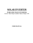
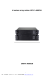
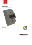
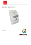
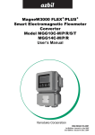
USER MANUAL
SUPER CHARGER
VERSION V1.0
Do not operate this device before reading
through all the information on the manual.
Please save this manual properly.
CONTENTS
1. Product introduction......................................................................... 1
1.1 Functions description ......................................................................... 1
1.2 Front panel ......................................................................................... 2
1.3 Rear panel .......................................................................................... 3
1.4 Product specification .......................................................................... 3
2. Installation........................................................................................... 5
2.1 Installation Safety Instructions ........................................................... 5
2.2 Unpacking and Inspection .................................................................. 6
2.3 Installation steps of wiring .................................................................. 7
3. Operation........................................................................................... 10
3.1 Operation Safety Instructions........................................................... 10
3.2 Start the Charger .............................................................................. 10
3.3 Turn off the Charger ......................................................................... 11
3.4 Operation in warning status ............................................................. 11
3.5 Operation in fault mode .................................................................... 11
4. Maintenance...................................................................................... 12
4.1 Maintenance Safety Instructions ...................................................... 12
4.1Typical Trouble Shooting ................................................................... 13
4.2Contact the service center................................................................. 14
5. Transport and Storage ..................................................................... 15
5.1 Please transport the Charger only in the original packaging........... 15
5.2 The Charger must be stored in the room where it is ventilated and dry.
.......................................................................................................... 15
1. Product introduction
The manual introduces two kinds of chargers; their
charging currents are 12A and 8A respectively.
1.1 Functions description
This is an external Charger; its maximum charging current can be
12/8A to shorten the charging time of battery banks markedly. It is
suitable for 240V/65AH (or bigger capacity) battery banks and adopts
three-stage charging method: It works on constant-current mode when
the battery voltage is low and the charging current is 12/8A; when the
battery voltage is high to 273V, the charging current will be 4A in order
to avoid overcharging the battery; when the battery voltage is higher
than 280V, charger will work on the floating charging mode, the
charger voltage is constant to 273V. The charging curve is shown
below:
C h a rg e r v o lta g e
280V dc
273V dc
T im e
C h a rg e r cu rre n t
1 2 /8 A
4A
T im e
1
1.2 Front panel
1.2.1 Front view
1) LED definition
There are total 3 LEDs to indicate the status of the Charger.
LED No.
Colour
1
Green
2
Yellow
3
Red
Name
Function
Normal/Status
LED
Indicate the Charger working well.
Indicate the Charger working status.
Warning LED
If it is turned on constantly, it shows
that the Charger is in Warning
status.
Fault LED
If it is turned on constantly, it shows
that the Charger is in Fault status
and the Charger will turn off.
2) LED action summary
LED NO.
1
Constant-current mode
★
4A charging-current mode
◇
Floating charging mode
●
2
3
●
Warning mode
●
Fault mode
2
★: Flashing every second
◇: Flashing every four seconds
●: Lightened constantly
1.3 Rear panel
1.4 Product specification
1.4.1 Electrical specifications
INPUT
Model No.
12A Charger 8A Charger
Phase
Single
Frequency
(46~75) Hz
Current (A)
21A Max
13.8A Max
Power Factor
>=0.96@ full load
Efficiency
90%
OUTPUT
Power rating
Voltage
3.3kW
2.2kW
273×(1±1%)VDC
3
1.4.2 Operating Environment
Ambient Temperature
0 ℃~ 40 ℃
Operating humidity
< 95%
Altitude
< 1000m
Storage temperature
0 ℃~ 40 ℃
1.4.3 Dimensions and weights
Model No.
Dimensions W x D x H (mm)
Net Weight (Kg)
12A Charger
340X250X110
6
8A Charger
340X250X110
5.5
1.4.4 Safety and EMC standard
Safety
IEC 60950-1/EN 60950-1
EMI
Conducted Emission:IEC/EN62040-2
Category C3
Radiated Emission:IEC/EN62040-2
Category C3
Harmonic Current:IEC/EN61000-3-2
(Input Current≤16A)
Voltage Fluctuations and Flicker:IEC/EN61000-3-3 (Input Current≤16A)
EMS
IEC/EN61000-4-2(ESD)
Level 4
IEC/EN61000-4-3(RS)
Level 3
IEC/EN61000-4-4(EFT)
Level 4
IEC/EN61000-4-5(Surge)
Level 4
IEC/EN 61000-4-6(CS)
Level 3
IEC/EN 61000-4-8(Power-frequency Magnetic field)
Level 3
EN61000-2-2 (Immunity to low frequency signals)
Warning: This is a product for commercial and industrial application in the
second environment-installation restrictions or additional measures may
be needed to prevent disturbances.
4
2. Installation
2.1 Installation Safety Instructions
You must read the following safety instructions before
installation!
●
Installation Personnel
This product must be installed only by qualified or
professional
personnel
according
to
safety
instructions!
●
Installation Environment
Do not install and operate the Charger when water
condensation happen which may occur if the Charger is moved
directly from a cold to a warm environment. The Charger must be
absolutely dry before being installed and operated. Please allow an
acclimatization time of at least 2 hours. Otherwise there is hazard of
electric shock!
Do not install the Charger in the environment where it is damp
or would be exposed to direct sunlight or near heat. Ensure the
Charger is far away from water, inflammable gas and corrosive
agents.
Do not block air vents in the housing of Charger. The Charger
must be installed in a location with good ventilation. Ensure enough
space on each side for ventilation.
5
●
Wiring & Grounding
Installation and Wiring must be performed in accordance with
the local electrical laws and regulations.
The Charger must be securely grounded. Make sure earth
connection and its reliability before connecting the power wires to
the wiring terminal of the building. Make sure the battery cabinets
have the equipotential earth bonding to the Charger main cabinet.
An appropriate switch device as backup protection for
over-current or short-circuit should be provided in the input utility.
To disconnect the battery from the Charger in any mode of
operation, an emergency switching device should be installed
between the Charger output terminal and the battery. It had better
has the leakage current protective function for safety.
●
Battery
The capacity of battery banks that connect with this Charger
must be 65AH or bigger.
DC breaker must be used as a protection device between the
battery banks and the Charger. The spec of protection must be
matched to the Charger specification.
2.2 Unpacking and Inspection
2.2.1 Unpack the package and check the contents. The shipped
package contains:
●
1 Charger
●
1 user manual
6
2.2.2 Inspect the appearance of the Charger to see if there is any
damage during transportation. Do not turn on the unit and
notify the dealer immediately if there is any damage or lack
of some parts.
2.3 Installation steps of wiring
1) Make sure the mains wire & breakers in the building are enough for
the rating of Charger to avoid the hazards of electric shock and
fire.
Note: Do not use the wall receptacle as the input power source for
the Charger, as its rated current is less than the Charger’s
maximum input current. Otherwise the receptacle may be burned
and destroyed.
2) Cut off the mains switch in the building before installation.
3) Turn off the battery switch before connect the battery to the Charger.
4) Prepare wires according to the following table:
Wiring spec (AWG)
Model
Input
Output
Ground
12A
12
12
12
8A
14
14
14
Note 1: The cable for 12A Charger should be able to carry the
current of >22A, the cross section area should be greater than 3.31
mm2. It is recommended to use 12 AWG wire or thicker for safety
and efficiency.
Note 2: The cable for 8A Charger should be able to carry the
current of >15A, the cross section area should be greater than 2.1
mm2. It is recommended to use 14 AWG wire or thicker for safety
and efficiency.
Note 3: The color of wires should be selected according to the local
electrical laws and regulations.
7
5) Remove the terminal block cover on the rear panel of Charger.
Then connect the wires according to the following terminal block
diagram: (Always connect the earth wire first!)
Wiring connection on the Charger rear panel
Warning:
●
Make sure a DC breaker or other protection device between the
Charger and battery banks is installed. If not, please install it carefully.
Switch off the battery breaker before installation.
●
Pay high attention to the rating battery voltage and it should be
240VDC, the connection with wrong battery voltage may cause
permanent damage of the Charger. Make sure the voltage of the
battery banks is correct.
●
Pay high attention to the rating battery capacity and it should be
bigger than 65AH, Wrong connection may cause permanent
damage of the battery
●
Pay high attention to the polarity mark on battery banks terminal
block, and make sure the correct battery polarity is connected.
Wrong connection may cause permanent damage of the Charger.
●
Make sure the battery input wiring is correct before power on. The
wire current spec, color, position, connection and conductance
reliability should be checked carefully. Make sure the +/- polarity is
correct, not reverse, no short circuit.
8
●
Make sure the protective earth ground wiring is correct. The wire
current spec, color, position, connection and conductance reliability
should be checked carefully.
●
Make sure the mains input & output wiring is correct. The wire
current spec, color, position, connection and conductance reliability
should be checked carefully. Make sure the L/N site is correct, not
reverse, no short circuit.
●
Install the terminal block cover on the rear panel of the Charger.
9
3. Operation
3.1 Operation Safety Instructions
You must read the following safety instructions before
operation!
●
operation personnel
Laymen can operate this product.
●
operation warning
Do not disconnect the earth conducting wire on the Charger or
the building wiring terminals in any time.
Do not try to disassemble the original part of the Charger before
turn off and disconnect it from the mains power and battery.
Do not make any liquid and foreign objects enter the Charger.
Turn off the mains input switch and battery banks switch
immediately at any accident of electric shock and fire related to the
Charger.
3.2 Start the Charger
1) Please switch on the battery breaker first;
2) If the wiring is correct, turn on the mains breaker. Then the power
supply inside the Charger will be started automatically, the fans will
run, and the panel will display the Charger’s working mode.
10
3.3 Turn off the Charger
1)
Firstly cut off the mains input switch of the Charger.
2) Then cut off the switch between charger and the battery banks, the
Charger will be shutdown completely.
3.4 Operation in warning status
1) In case the Warning LED is Lightened constantly, it shows that the
Charger system have some troubles, please check the
troubleshooting table in chapter 4 to find out what happen to the
Charger.
2) If the error is corrected, the warning alarm will stop.
3.5 Operation in fault mode
1) In case the Fault LED is lightened constantly, it shows that there is
must a fatal error happen to the UPS and it is operating in abnormal
mode.
2) Please check your battery banks, wiring, ventilation, mains, and so
on after the fault happens. Don’t try to turn on the Charger again
before find out the reason. If the trouble can’t be shoot, please
contact the distributor or service people.
3) In the emergency case, please cut off the connection from mains /
battery banks / output immediately to avoid more risk or danger.
11
4. Maintenance
4.1 Maintenance Safety Instructions
You must read the following safety instructions before
maintenance!
●
Maintenance Personnel
This product must be maintained only by qualified
professional
personnel
according
to
safety
instructions!
●
Risk of electric shock
No matter the Charger is connected to the utility power or not,
the output may have electricity. The parts (capacitor) inside the unit
may still have hazardous voltage after turning off the Charger.
Verify that no battery connects to the output terminals.
Verify that no hazardous voltage exists in the energy storage
capacitor before maintenance or repair.
Remove all jewellery, wristwatches, rings and other metal
personal goods before maintenance or repair.
Only use tools with insulated grips and handles when
maintaining or repairing.
●
Fuse
Please replace the fuse only by a fuse of the same type and of
the same amperage in order to avoid fire hazards.
12
4.1Typical Trouble Shooting
If the Charger does not operate correctly, please attempt to solve the
problem using the table below.
Problem
Possible cause
Remedy
No indication,
LED is not
bright and the
fan is dead
No input voltage or input
fuse is broken
Check input power source and
input fuse.
Warning LED is
turned on
constantly and
there is output.
Fan fault
Check the fan
Warning LED is
turned on
constantly and
there is no
output
Input voltage or frequency
abnormal、battery voltage
too low or overcharging
Check the input power source
and battery.
Over temperature
Make sure the air vents are not
blocked and the ambient
temperature is not too high.
Remove the battery and wait for
10 minutes for the Charger to
cool down before turning on
again. If failed, please contact the
distributor or service center.
Output short
Turn off the Charger. Ensure that
the battery is not failed or the
charger has no internal faults
before turning it on again. If
failed, please contact the
distributor or service center.
Output fuse open-circuit
Check the output fuse
Fault LED is
turned on
constantly
13
4.2Contact the service center
If contact the service center for trouble shooting, please provide the
information as following:
●
Model name of product.
●
Serial number of product.
●
The date when the problem found.
●
LED display status.
●
Mains power condition
●
battery type and capacity.
●
Environment temperature, ventilation status.
●
Other information for complete description of the problem.
14
5. Transport and Storage
5.1 Please transport the Charger only in the original
packaging.
5.2 The Charger must be stored in the room where it is
ventilated and dry.
15
614-00288-00
16