Download INSTRUCTION MANUAL ELECTRIC PATIENT LIFTS
Transcript
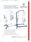
Pantone 7452C Pantone 431C HYDRAULIC patient lift RP800-HYDRAULIC actuator, load 150Kg MA RP800_805_806_807_810_811_815 02 A_12 - 2010 Electric patient lifts RP805 - LINAK actuator, load 150Kg RP806 - HIWIN actuator, load 150Kg RP807 - LINAK Jumbo Home actuator, load 150Kg RP810 - LINAK actuator, load 180Kg RP811 - HIWIN actuator, load 180Kg STAND UP LIFT RP815 - LINAK actuator, load 150Kg Instruction manual Moretti S.p.A. Fax +39 055 96 21 200 Via Bruxelles 3 - Meleto www.morettispa.com 52022 Cavriglia (Arezzo) - Italy [email protected] Tel. +39 055 96 21 11 2 Pantone 7452C Pantone 431C Pantone 7452C Pantone 431C READ THIS MANUAL CAREFULLY BEFORE USING THE DEVICE CONTENTS MODEL CODES. . . . . . . . . . . . . . . . . . . . . . . . . . . . . . . . . . . . . . . . . . . . . . . . . . . . page 3 INTRODUCTION. . . . . . . . . . . . . . . . . . . . . . . . . . . . . . . . . . . . . . . . . . . . . . . . . . . page 3 INTENDED PURPOSE. . . . . . . . . . . . . . . . . . . . . . . . . . . . . . . . . . . . . . . . . . . . . . page 3 DECLARATION OF EC CONFORMITY. . . . . . . . . . . . . . . . . . . . . . . . . . . . . . . page 3-4 DIMENSIONS. . . . . . . . . . . . . . . . . . . . . . . . . . . . . . . . . . . . . . . . . . . . . . . . . . . page 4-5 DESCRIPTION OF PARTS. . . . . . . . . . . . . . . . . . . . . . . . . . . . . . . . . . . . . . . page 5-6-7 LIFT ASSEMBLY INSTRUCTIONS. . . . . . . . . . . . . . . . . . . . . . . . . . . . . . . . . . . . page 8 Structure of RP800 (hydraulic). . . . . . . . . . . . . . . . . . . . . . . . . . . . . . . . . . . page 8 Structure of RP805-806-807-810-811 (electric) . . . . . . . . . . . . . . . . . . . . page 8 ELECTRICAL KIT INSTALLATION INSTRUCTIONS. . . . . . . . . . . . . . . . . . . . . . page 8 Electrical kit for RP805-810 . . . . . . . . . . . . . . . . . . . . . . . . . . . . . . . . . . . . page 8-9 Electrical kit for RP807 . . . . . . . . . . . . . . . . . . . . . . . . . . . . . . . . . . . . . . . . . . page 9 Electrical kit for RP806-811. . . . . . . . . . . . . . . . . . . . . . . . . . . . . . . . . . . . . . . page 9 ASSEMBLY INSTRUCTIONS FOR RP815 STAND UP LIFT. . . . . . . . . . . . . page 10-11 INSTRUCTIONS FOR USING LIFTS. . . . . . . . . . . . . . . . . . . . . . . . . . . . . . . . . . page 10 RP800 lift (hydraulic). . . . . . . . . . . . . . . . . . . . . . . . . . . . . . . . . . . . . . . . . page 10-11 RP805-810 lifts (electric). . . . . . . . . . . . . . . . . . . . . . . . . . . . . . . . . . . . . . page 11-12 RP807 lift (electric). . . . . . . . . . . . . . . . . . . . . . . . . . . . . . . . . . . . . . . . . . . . . page 12 RP806-811 lifts (electric) . . . . . . . . . . . . . . . . . . . . . . . . . . . . . . . . . . . . . page 13-14 INSTRUCTIONS FOR USING THE RP815 STAND UP LIFT. . . . . . . . . . . . page 14-15 PHOTOGRAPHS. . . . . . . . . . . . . . . . . . . . . . . . . . . . . . . . . . . . . . . page 16-17-18-19-20 WARNINGS. . . . . . . . . . . . . . . . . . . . . . . . . . . . . . . . . . . . . . . . . . . . . . . . . . . . . . page 21 CLEANING . . . . . . . . . . . . . . . . . . . . . . . . . . . . . . . . . . . . . . . . . . . . . . . . . . . . . . page 21 MAINTENANCE. . . . . . . . . . . . . . . . . . . . . . . . . . . . . . . . . . . . . . . . . . . . . . . . . . page 21 SPARE PARTS. . . . . . . . . . . . . . . . . . . . . . . . . . . . . . . . . . . . . . . . . . . . . . . . . . . page 21 DISPOSAL OF BATTERIES AND ELECTRONIC COMPONENTS. . . . . . . . page 21-22 WARRANTY. . . . . . . . . . . . . . . . . . . . . . . . . . . . . . . . . . . . . . . . . . . . . . . . . . . . . page 23 3 Pantone 7452C Pantone 431C Pantone 7452C Pantone 431C Class 1 medical device, Italian Legislative Decree dated 24/02/97 n. 46 implementing Directive 93/42/EEC and subsequent amendments Codes HYDRAULIC PATIENT LIFT RP800 - HYDRAULIC actuator, load 150Kg ELECTRIC PATIENT LIFTS RP805 - LINAK actuator, load 150Kg RP806 - HIWIN actuator, load 150Kg RP807 - LINAK Jumbo Home actuator, load 150Kg RP810 - LINAK actuator, load 180Kg RP811 - HIWIN actuator, load 180Kg STAND UP LIFT RP815 - LINAK actuator, load 150Kg INTRODUCTION Thank you for choosing a patient lift/stand up lift from the MOPEDIA by MORETTI S.p.A. product range. The design and quality of these products is a guarantee of comfort, safety and reliability. MOPEDIA by MORETTI S.p.A. patient lifts/stand up lifts by MORETTI are designed and built to meet all your demands for practical, correct use. This user's manual provides some suggestions as to how to correctly use the lift you have chosen and gives some valuable advice for your safety. Please read through the manual carefully before using the patient lift/stand up lift. Should you have any queries, please contact your retailer for advice and assistance. INTENDED USE MOPEDIA patient lifts/stand up lifts are intended to lift and move people with motor difficulties. An assistant operates the machine. They cannot be used by one person alone. MORETTI S.p.A. refuses all liability for damages caused by improper use of the device or by its use for a purpose other than that specified in this manual. DECLARATION OF CE CONFORMITY MORETTI S.p.A. hereby declares, under its own exclusive responsibility, that the products manufactured and sold by MORETTI S.p.A. and belonging to the PATIENT LIFT/STAND UP LIFT category are compliant with the applicable provisions outlined in the Medical Devices Directive 93/42/EEC. To this end MORETTI S.p.A. guarantees and declares as follows, under its own responsibility: 1.The devices in question satisfy the essential requirements of Annex I of directive 93/42/ EEC as prescribed by Annex VII of the said directive. 2.A complete list of the devices in question is available in Annex A to this declaration. 3. The devices in question ARE NOT MEASUREMENT TOOLS. 4. The devices in question ARE NOT INTENDED FOR CLINICAL INVESTIGATION. 5. The devices in question are sold in NON STERILE packing. 6. The devices in question should be considered as belonging to class I. 7. DO NOT use/install the devices in question for any other purpose than that expressly indicated by MORETTI S.p.A. 8. MORETTI S.p.A. maintains and submits the documentation certifying conformity with Directive 93/42/EEC to the proper authorities. 4 Pantone 7452C Pantone 431C Pantone 7452C Pantone 431C DIMENSIONS RP800 RP805 - RP806 - RP807 - RP810 - RP811 5 Pantone 7452C Pantone 431C Pantone 7452C Pantone 431C RP815 DESCRIPTION OF PARTS Structure of P800 A - 1 wheeled base B - 1 mast with boom and hydraulic actuator C - 2 handles D - 1 lever E - 1 two-boom hook F - 1 cradle G - 1 assembly wrench Structure of RP805-806-807-810-811 A - 1 wheeled base B - 1 mast with boom C - 2 handles D - 1 lever E - 1 two-boom hook F - 1 cradle G - 4 M6x10mm allen bolts H - 2 M5x80mm screws (use only with RP807) I - n.2 allen keys for assembly 6 Pantone 7452C Pantone 431C Pantone 7452C Pantone 431C Structure of P815 A - 1 wheeled base B - 1 mast with boom and hydraulic actuator C - 1 footplate D - 1 lever E - 1 cradle F - 1 threaded handle for mast G -1 LINAK remote control H - 1 LINAK control unit I - 1 LINAK battery L - 1 mount for LINAK battery M -1 battery charger adapter Electrical kit for RP805 - 810 A - 1 mount for LINAK battery B - 1 LINAK remote control C - 1 battery charger adapter D - 1 LINAK battery E - 1 LINAK control unit F - 1 LINAK actuator, load 150Kg (RP805 only) G - 1 LINAK actuator, load 180Kg (RP810 only) 7 Pantone 7452C Pantone 431C Pantone 7452C Pantone 431C Electrical kit for RP806 - 811 A - 1 HIWIN remote control B - 1 battery charger adapter C - 1 battery charger adapter cable D - 1 HIWIN battery E - 1 HIWIN control unit F - 1 HIWIN actuator, load 150Kg (RP806 only) G - 1 HIWIN actuator, load 180Kg (RP811 only) Electrical kit for RP807 A - 1 LINAK actuator, load 150Kg B - 1 LINAK remote control C - 1 LINAK Jumbo Home battery D - 1 LINAK actuator cable E - 1 plastic clamp F - 1 plastic cap G - 2 M5x10mm screws H - 1 plastic cover I - n.1 battery charge adapter 8 Pantone 7452C Pantone 431C Pantone 7452C Pantone 431C ASSEMBLY INSTRUCTIONS FOR RP800 PATIENT LIFT STRUCTURE 1. Remove the safety clip from the pin securing the base, then extract the pin 2. Remove the two M8 hex bolts from the mast 3.Fit the mast with hydraulic pump into the base, making sure to locate the boom on the same side as the legs (fig.1) 4.Refit the pin and secure it with the safety clip, then screw the two hex bolts back in (fig.2) 5. Screw the two handles into the mast and tighten down the locknut (fig.3) 6.Fit the opening lever and check that the locking clip has engaged in the right position (fig.4) 7.Fit the lifting beam into the U-shaped hook located on the end of the boom (fig.5). 8. The lift is now fully assembled and ready for use ASSEMBLY INSTRUCTIONS FOR RP805-806-807-810-811 PATIENT LIFT STRUCTURES 1. Remove the bolts from the base and mast 2.Fit the mast into the rectangular seating in the base, taking care that the boom is located on the same side as the legs (fig.6) 3.Tighten down the bolts securing the mast to the base: the long one goes in the top hole and the short one in the bottom hole (fig.7) 4.Fit the handles into their mounts and secure them with the 4 short screws (fig.8) 5.Fit the opening lever and check that the locking clip has engaged in the right position (fig.9) 6.Fit the lifting beam into the U-shaped hook located on the end of the boom (fig.10). 7.The structure is now properly assembled; install the electrical kit as explained in the instructions for the particular type of lift you are using. ELECTRICAL KIT INSTALLATION INSTRUCTIONS FOR RP 805-810 (LINAK actuators, load 150 and 180 Kg) 1. Remove the two actuator mounting bolts on the mast boom 2.Fit the actuator and secure it with the two bolts. Fit the plastic cap to the nuts (fig.11) 3.Secure the control unit bracket to the mast with the two small crosshead screws (the mast is fitted with 3 such screws, but only use 2 of them). N.B. the mast and bracket have three holes each: use only the first and second holes from the top (fig.12) 4.Mount the LINAK control unit to the bracket - make sure it fits properly into the lower guides and secure it with the small allen bolt (fig.13) 5.Fit the LINAK battery to the top of the control unit so that the lower part mates correctly and then push it towards the bracket until the clip at the top engages (fig.14) 6.Connect the actuator's connector to control unit socket “1” - make sure it is fully inserted (fig.15) 7.Connect the remote control's connector to the large socket on the control unit - make sure the guide lug seats properly and then push it all the way in (fig.15) 9 Pantone 7452C Pantone 431C Pantone 7452C Pantone 431C ELECTRICAL KIT INSTALLATION INSTRUCTIONS FOR RP 807 (LINAK Jumbo Home actuator, load 150 Kg) 1. Remove the two actuator mounting bolts on the mast boom 2.Fit the actuator and secure it with the two bolts. Fit the plastic cap to the nuts (fig.11) 3.Mount the complete battery pack to the lift's column using the two long M5x80mm bolts (fig.16) N.B. first screw both bolts in a short way, and then tighten them down equally until they are fully secured 4. Connect one end of the extension cord to the actuator's connector (make sure the guide lug is properly seated) and secure it with the plastic clip (fig.17) 5. Connect the other end of the extension cord to the RH socket on the battery pack (fig.18) 6.Connect the remote control connector to the corresponding socket on the control unit (make sure the guide lug is properly seated) (fig.18) 7.Fit the cap to the free socket on the control unit and fit the plastic cover with its two small M4x10mm bolts (fig.19) ELECTRICAL KIT INSTALLATION INSTRUCTIONS FOR RP 806-811 (HIWIN actuators, load 150-180Kg) 1. Remove the two actuator mounting bolts on the mast boom 2.Fit the actuator and secure it with the two bolts. Fit the plastic cap to the nuts (fig.11) 3.Secure the control unit bracket to the mast with the two small crosshead screws (the mast is fitted with 3 such screws, but only use 2 of them). N.B. the mast and bracket have three holes each: use only the first and second holes from the top (fig.20) 4.Mount the battery by aligning the pins on its back with the holes on the control unit slide, then push it downwards until the yellow clip engages (fig.21) 5.Fit the actuator connector to the bottom centre socket on the control unit (marked “1“) and push it all the way in (fig.22) 6.Connect the remote control connector to the LH socket on the control unit (marked “KP”): make sure the lug is aligned. Now push it all the way in (fig.22). 10 Pantone 7452C Pantone 431C Pantone 7452C Pantone 431C ASSEMBLY INSTRUCTIONS FOR RP815 STAND UP LIFT 1.Fit the mast into the base with the boom located on the same side as the wheels and secure the assembly with the handle and rear M12x20 mm hex bolt (fig.23) 2. Raise the legs cushion and lock it with the knob (fig.24) 3. Position the footplate on the base (fig.25) 4.Mount the actuator to the boom with its pin and secure it with the clip (fig.26) N.B. The lower part of the actuator is already mounted to the structure. 5.Fit the opening lever and check that the locking clip has engaged in the right position (fig.27) 6.Secure the control unit bracket to the mast with the 3 crosshead screws on the mast itself (fig.28) 7.Mount the LINAK control unit to the bracket - make sure it fits properly into the lower guides and secure it with the small allen bolt (fig.13) 8.Fit the LINAK battery to the top of the control unit, so that its base engages properly, and then push it in towards the bracket until the clip at the top engages. (fig.14) 9.Connect the actuator's connector to control unit socket “1” - make sure it is fully inserted (fig.15) 10.Connect the remote control's connector to the large socket on the control unit - make sure the guide lug mates properly and then push it all the way in (fig.15) INSTRUCTIONS FOR USING THE RP800 PATIENT LIFT 1. Before lifting a patient, open the base legs to the maximum width possible, gently pulling the opening lever towards you and locking it in the open position (fig.29) 2. Lock the rear wheel brakes (fig.30) 3. Keep the patient centred between the base legs and always turned towards the assistant 4. Hook the cradle straps securely onto the lifting beam 5.make sure the hydraulic pump valve is fully closed (turn it in the direction marked CLOSE) (fig.32) 6. Actuate the pumping lever to start lifting 7.Keep an eye on the patient's position throughout! 8.Lift the patient to the desired height, keeping him facing his assistant at all times (fig.31) 9. Release the rear wheel (fig.30) and move the patient 10.Before lowering the patient, lock the rear wheels again 11.Start lowering the patient by slowly turning the hydraulic pump valve in the direction marked OPEN (fig.32) N.B. To lower the patient slowly, open the valve just a little bit; opening it further lowers the patient more rapidly 12.Keep an eye on the patient's position throughout! HELP THE PATIENT WHILE LOWERING HIM SO AS TO MAINTAIN THE CORRECT SEATED POSITION! 11 Pantone 7452C Pantone 431C Pantone 7452C Pantone 431C INSTRUCTIONS FOR USING THE RP805-810 PATIENT LIFT BEFORE USING THE ELECTRIC LIFT, CHARGE THE BATTERIES FOR 6 HOURS 1.Before lifting a patient, open the base legs to the maximum width possible, gently pulling the opening lever towards you and locking it in the open position (fig.33) 2. Lock the rear wheel brakes (fig.34) 3. Keep the patient centred between the base legs and always turned towards the assistant 4. Hook the cradle straps securely onto the lifting beam 5. Raise the patient by pressing the up arrow button (fig.35) 6.Keep an eye on the patient's position throughout 7.Lift the patient to the desired height, keeping him facing his assistant at all times (fig.36) 8. Release the rear wheels and move the patient 9. Before lowering the patient, lock the rear wheels again 10.Use the down arrow button to lower the patient (fig.35) 11.Keep an eye on the patient's position throughout! HELP THE PATIENT WHILE LOWERING HIM SO AS TO MAINTAIN THE CORRECT SEATED POSITION! EMERGENCY STOP The control unit is equipped with a red “STOP” button which instantly deactivates all controls when pressed. To restore normal operation, turn the button clockwise and pull it outwards (fig.15) EMERGENCY DESCENT Underneath the STOP button, there is a small “Emergency” button on the control unit for lowering patients when the remote control fails to operate properly. (fig.15) N.B. This button can only be operated with the aid of a sharp pointed object like the tip of a pen. ACTUATOR FAST DISCHARGE (RP810 only) When using the emergency descent, please ensure that this is done guaranteeing complete patient safety. The actuator of the RP810 lift with 180 Kg load has a red quick release for emergency lowering of the patient if the electrical equipment fails to operate correctly, or if the patient requires immediate assistance. To operate the emergency descent device, raise the red control (fig.37) N.B. The emergency quick release is completely mechanical, and is calibrated to operate under a certain load; attempting to operate it without a patient supported by the lifting beam will have no effect. 12 Pantone 7452C Pantone 431C Pantone 7452C Pantone 431C RECHARGING THE BATTERIES •Connect the adapter to the mains socket and then to the control unit socket (fig.15), or disconnect the battery and connect the adapter directly to the battery socket (fig.38) •Before operating the lift again, make sure to disconnect the battery charger! • Charge the batteries for at least 6 hours before operating the lift •You can also charge the batteries with the wall charger (OPTIONAL) INSTRUCTIONS FOR USING THE RP807 LIFT BEFORE USING THE ELECTRIC LIFT, CHARGE THE BATTERIES FOR 6 HOURS 1.Before lifting a patient, open the base legs to the maximum width possible, gently pulling the opening lever towards you and locking it in the open position (fig.33) 2. Lock the rear wheel brakes (fig.34) 3. Keep the patient centred between the base legs and always turned towards the assistant 4. Hook the cradle straps securely onto the lifting beam 5.Raise the patient with the “raise” button (the green led lights up on the control unit) (fig.39-40) 6.Keep an eye on the patient's position throughout! 7.Lift the patient to the desired height, keeping him facing his assistant at all times (fig.36) 8. Release the rear wheels and move the patient 9. Before lowering the patient, lock the rear wheels again 10.Lower the patient with the “lower” button (the green led lights up on the control unit) (fig.39-40) 11.Keep an eye on the patient's position throughout! HELP THE PATIENT WHILE LOWERING HIM SO AS TO MAINTAIN THE CORRECT SEATED POSITION! EMERGENCY STOP The control unit is equipped with a red “STOP” button which instantly deactivates all controls when pressed. To restore normal operation, turn the button clockwise and pull it outwards (fig.40) EMERGENCY DESCENT Below the two leds on the control unit is a button marked with a downwards arrow for emergency lowering if the remote control is not operating properly. (fig.40) RECHARGING THE BATTERIES • Connect the adapter to the mains socket and then to the socket on the control unit (fig.18) 13 Pantone 7452C Pantone 431C Pantone 7452C Pantone 431C N.B. When the battery is charging, an orange led lights up on the battery's front panel and all controls are automatically disabled (fig.40) •Before operating the lift again, make sure to disconnect the battery charger! • Charge the batteries for at least 6 hours before operating the lift INSTRUCTIONS FOR USING THE RP806-811 LIFT BEFORE USING THE ELECTRIC LIFT, CHARGE THE BATTERIES FOR 6 HOURS 1.Before lifting a patient, open the base legs to the maximum width possible, gently pulling the opening lever towards you and locking it in the open position (fig.33) 2. Lock the rear wheel brakes (fig.34) 3. Keep the patient centred between the base legs and always turned towards the assistant 4. Hook the cradle straps securely onto the lifting beam 5. Raise the patient by pressing the up arrow button (fig.41) 6.Keep an eye on the patient's position throughout! 7.Lift the patient to the desired height, keeping him facing his assistant at all times (fig.36) 8. Release the rear wheels and move the patient 9. Before lowering the patient, lock the rear wheels again 10.Use the down arrow button to lower the patient (fig.41) 11.Keep an eye on the patient's position throughout! HELP THE PATIENT WHILE LOWERING HIM SO AS TO MAINTAIN THE CORRECT SEATED POSITION! EMERGENCY STOP The control unit is equipped with a red “STOP” button which instantly deactivates all controls when pressed. To restore normal operation, turn the button clockwise and pull it outwards (fig.42) EMERGENCY CONTROLS The control unit is equipped with two buttons (arrow up and arrow down) which can be used instead of those on the remote control if the latter is not operating correctly. (fig.42) ACTUATOR FAST DISCHARGE (RP811 only) When using the emergency descent, please ensure that this is done guaranteeing complete patient safety. The actuator of the RP811 lift with 180 Kg load has a quick release for emergency lowering of the patient if the electrical equipment fails to operate correctly, or if the patient requires immediate assistance. To activate the emergency descent, raise the metal ring control. (fig.43) 14 Pantone 7452C Pantone 431C Pantone 7452C Pantone 431C N.B. The emergency quick release is completely mechanical, and is calibrated to operate under a certain load; attempting to operate it without a patient supported in the cradle will have no effect. BATTERY CHARGE INDICATION Lift model RP806-811 is equipped with a 4 led battery charge indicator. This is present on the remote control and on the control unit front panel. To display the battery charge, press one of the two buttons (arrow up/down). If all four leds light up, the battery is fully charged, while if just one lights up, the battery needs recharging. (fig.41) and (fig.42) RECHARGING THE BATTERIES •Connect the adapter to the mains socket and then to the control unit socket after removing the protective cap (fig.22) •The charger adapter has a led which is red while charging is in progress. Charge the battery until the led turns green. •Before operating the lift again, make sure to disconnect the battery charger! • Charge the batteries for at least 6 hours before operating the lift • You can also charge the batteries with the wall charger (OPTIONAL) INSTRUCTIONS FOR USING THE RP815 STAND UP LIFT BEFORE USING THE ELECTRIC STAND UP LIFT, CHARGE THE BATTERIES FOR 6 HOURS 1.Before lifting a patient, open the base legs to the maximum width possible, gently pulling the opening lever towards you and locking it in the open position (fig.44) 2. Stand in front of the seated patient N.B. IF THE PATIENT IS SEATED IN A WHEELCHAIR, MAKE SURE ITS WHEELS ARE LOCKED BEFORE PROCEEDING. 3. Lock the rear wheels of the stand up lift (fig.45) 4. Keep the patient centred between the base legs and always turned towards the assistant 5.Place the patient's feet on the base and adjust the height and depth of the leg support to suit the patient's stature with the adjuster knobs (fig.46) 6. Hook the cradle straps securely onto the boom 7. Make sure the patient is holding the lift's handles, if able to do so 8. Keep an eye on the patient's position throughout 9. Raise the patient by pressing the up arrow button (fig.35) 10.Raise the patient until he is standing on his own two feet (fig.47) 11. Release the wheels and move the patient 12.Move to the new seated position and lock the lift's wheels once more 15 Pantone 7452C Pantone 431C Pantone 7452C Pantone 431C N.B. IF THE PATIENT IS TO BE SEATED IN A WHEELCHAIR, MAKE SURE ITS WHEELS ARE LOCKED BEFORE PROCEEDING. 13.Lower the patient with the arrow down button (fig.35) 14.Keep an eye on the patient's position throughout HELP THE PATIENT WHILE LOWERING HIM SO AS TO MAINTAIN THE CORRECT SEATED POSITION! EMERGENCY STOP The control unit is equipped with a red “STOP” button which instantly deactivates all controls when pressed. To restore normal operation, turn the button clockwise and pull it outwards (fig.37) EMERGENCY DESCENT Underneath the STOP button, there is a small “Emergency” button on the control unit for lowering patients when the remote control fails to operate properly. (fig.38) N.B. This button can only be operated with the aid of a sharp pointed object like the tip of a pen. RECHARGING THE BATTERIES •Connect the adapter to the mains socket and then to the control unit socket (fig.15), or disconnect the battery and connect the adapter directly to the battery socket (fig.38) •Before operating the lift again, make sure to disconnect the battery charger! • Charge the batteries for at least 6 hours before operating the lift • You can also charge the batteries with the wall charger (OPTIONAL) 16 PHOTOGRAPHS fig.1 Pantone 7452C Pantone 431C fig.2 fig.3 fig.5 fig.4 fig.7 Pantone 7452C Pantone 431C fig.6 fig.8 fig.9 fig.10 fig.12 fig.11 17 Pantone 7452C Pantone 431C Pantone 7452C Pantone 431C fig.13 STOP button (turn clockwise to reset) use a narrow-tipped object safety clip fig.14 remote control actuator battery charger fig.16 fig.17 fig.15 fig.19 fig.20 actuator extension cord not connected battery charger remote control fig.18 18 Pantone 7452C Pantone 431C fig.24 Pantone 7452C Pantone 431C fig.28 bracket screws safety clip fig.21 fig.22 open close battery charger fig.29 fig.25 lock pin remote control actuator safety ring fig.30 fig.26 fig.31 fig.23 fig.27 locking clip release 19 Pantone 7452C Pantone 431C Pantone 7452C Pantone 431C fig.32 open fig.39 close open closed fig.33 raise lower lock fig.34 release fig.35 fig.40 fig.36 STOP raise charging led lower fig.38 pull up to activate emergency descent lower fig.37 charger socket confirm led 20 Pantone 7452C Pantone 431C operating indicator raise lower Pantone 7452C Pantone 431C fig.42 pull ring up to activate emergency descent fig.43 raise lower fig.44 close open charge level fig.41 lock charge level fig.46 height adjustment extension adjustment fig.45 release fig.47 21 Pantone 7452C Pantone 431C Pantone 7452C Pantone 431C Warnings •The lift is designed for moving patients with motor problems for short distances, for instance, from a bed to a wheelchair or comfortable chair, and back. It must not be used for transporting the patient. • While lifting the patient, make sure the legs of the base are as far apart as possible, that the control lever is securely locked at that position and the rear wheel brakes are engaged. • While moving the patient between locations, keep an eye out for obstacles that might cause the lift to tip over. • Always check that the cradle is in good condition. Do not use cradles showing signs of damage or wear. CLEANING To clean the harness and structure use a solution of alcohol and neutral soap (in equal parts) mixed with water. MAINTENANCE • It is extremely important to check the lift before each use: • More specifically, please check that all screws and bolts are well tightened. • That the lift can move freely with the wheel brakes not on. • Check that the rear wheel brakes function correctly. • It is very important to regularly check that the connection pins and stop rings are correctly located (the pins connect the actuator to the lift at the top and bottom, and the lifting beam to the cradle). • The mechanical parts must be lubricated with a drop of oil in order to assist their sliding and resistance to wear. In particular, make sure the linkage which opens the legs of the lft is operating correctly. Lubricate as indicated above every two or three months. SPARE PARTS For spare parts and accessories, refer to the MORETTI master catalogue. Only use original MORETTI accessories. Failure to do so will entail our refusing all liability for any incident caused by improper use. DISPOSAL OF BATTERIES AND ELECTRONIC COMPONENTS DISPOSAL INSTRUCTIONS, AS REQUIRED BY DIRECTIVE 2002/96/EC: At the end of its service life, the product may not be disposed of together with normal municipal waste. It must be delivered to the municipal sorted disposal centre or to the reseller, who provides this service. Sorted waste disposal reduces the environmental and health consequences of improper disposal and enables its materials to be recycled, thus resulting in energy and resource savings. To highlight the requirement for sorted disposal of electromedical equipment, the product bears the barred bin symbol. 22 Pantone 7452C Pantone 431C Pantone 7452C Pantone 431C TREATMENT OF EXHAUSTED BATTERIES (Directive 2006/66/CE): This symbol indicates that the batteries may not be treated like common household waste. Make sure the batteries are disposed of properly; this prevents the possible environmental and health consequences of incorrect disposal. Recycling helps to conserve natural resources. Deliver exhausted batteries to a proper recycling centre. For more detailed information regarding the disposal of exhausted batteries or the product itself, contact the municipality, local waste disposal service or the reseller from whom you purchased the device. 23 Pantone 7452C Pantone 431C Pantone 7452C Pantone 431C Warranty This product is guaranteed for 2 YEARS from the purchase date. The distributor reserves the right to repair or replace any parts affected by production defects or defects in the materials used, at no expense for the customer. The warranty shall not apply in the event of damage caused by improper use, abuse, alterations or dismantling by unauthorized persons. For effecting repairs in compliance with the above-mentioned conditions for validating the warranty, send the product together with the purchase receipt to the nearest dealer. ----------------------------------------------------------------------- Pantone 7452C Pantone 431C Pantone 7452C Pantone 431C WARRANTY CERTIFICATE Product____________________________________________________________ Purchased on (date)_________________________________________________ Dealer _____________________________________________________________ Street_______________________ Town _________________________________ Sold to ____________________________________________________________ Street_______________________ Town_ ________________________________ Moretti S.p.A. Via Bruxelles 3 - Meleto 52022 Cavriglia (Arezzo) - Italy - Tel. +39 055 96 21 11 www.morettispa.com email: [email protected] MADE IN P.R.C.


