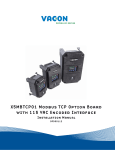
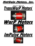
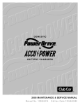
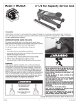
1
Controllers
By: NetGain Controls, Inc.
Powering the future!
Owner's Manual
Firmware Version 27-Jul-11 to Current
© 2011 All Rights Reserved
NetGain Controls, Inc.
1 of 25
Table of Contents
IMPORTANT...............................................................................................................................................3
WarP-Drive Purchase Record......................................................................................................................5
Thank You from NetGain Controls, Inc.......................................................................................................6
NEW CONTROLLER LIMITED WARRANTY........................................................................................7
Specifications and Features..........................................................................................................................8
Safety Information.......................................................................................................................................9
Installation..................................................................................................................................................11
Preparation.............................................................................................................................................11
Physical Mounting................................................................................................................................12
Low Current Wiring..............................................................................................................................12
12V Power, Ignition, Brake, Reverse, and Contactor Control:.............................................................13
Liquid Cooling......................................................................................................................................16
High Current Wiring.............................................................................................................................17
CANbus Connections............................................................................................................................18
Operation....................................................................................................................................................20
Starting the system................................................................................................................................20
Throttle input.........................................................................................................................................20
LED purposes........................................................................................................................................21
Diagnostic Error Code (DTC) Errors and Warnings.............................................................................22
View DTC's on the onboard LEDs...................................................................................................22
Diagnostic Trouble Codes (DTC's) index........................................................................................23
CAUTION..................................................................................................................................................25
NOTES.......................................................................................................................................................26
2 of 25
IMPORTANT
The symbol
used throughout this document indicates that it is
an extremely critical aspect of the installation or tuning and
particular care should be exercised.
3 of 25
WarP-Drive Purchase Record
Please record your controller serial number and date of purchase on this page.
Controller Serial Number: _________________________________________
Date of Purchase:_____________________________________________
Purchased From:______________________________________________
Controller Model:
4 of 25
July 27, 2011
RE: Your new NetGain Controls, Inc. WarP-Drive™ Controller
Dear Customer:
We would like to “Thank You” for your purchase.
Please read this document carefully and follow the suggestions that will provide for years of great
performance from your new controller.
This Owner's Manual contains the new controller warranty, our safety information sheet, and test
procedures, as well as other information of interest and importance.
There is also a substantial amount of content that may be obtained at our website:
http://www.ngcontrols.com
Along with your dealer, we definitely want to help make your EV project a success, so please let us
know if you have any questions about your controller, safety, wiring or anything else. We'll help you or
find resources that can help.
Again, we thank you for your controller purchase – we wish you success in your EV project!
Ryan J. Bohm
NetGain Controls, Inc.
President
Thank You from NetGain Controls, Inc.
5 of 25
WarP-Drive Controller
NEW CONTROLLER LIMITED WARRANTY*
NetGain Controls, Inc. (The Company), warrants that new controllers sold by it are merchantable and free of
defects in material and workmanship at the time that they are shipped from the company’s factory.
The company makes no warranty with respect to the new controller other than the warranty stated above. All
implied warranties of merchantability and all express and implied warranties of any other kind are hereby
excluded.
The company will repair or, at its option, replace any part of any new controller sold by it that fails to conform to
the warranty stated above, provided NetGain Controls, Inc. (factory) is contacted for a Repair Authorization
Number (RA#) and such part is returned to the company’s factory or to a factory authorized service station,
transportation charges prepaid, within the warranty period specified below:
NEW CONTROLLER WARRANTY extends for a period of one year or 2000 hours of
equipment operation, whichever first occurs, following the date of delivery of such
equipment into which the controller has been installed, but warranty coverage will not
exceed a period of two years from the date the controller was shipped from the
company’s factory. Proof of equipment installation date and equipment hour meter
reading must be provided.
LIMITATION OF LIABILITY
The company’s liability, whether in contract or in tort or under any other legal theory, arising out of warranties,
representations, instruction or warnings (or any lack or inadequacy thereof), deficiencies, failures or defects of
any kind or from any cause shall be limited exclusively to repairing or replacing parts (during normal business
hours) under the provisions stated above. All liability for damages, including, but not limited to, those expenses,
or injury to business credit, reputation or financial standing is hereby excluded.
The warranties contained therein shall not apply to or include any of the following and the company shall have no
liability with respect to:
1. Repair or replacement required as a result of: (A) accident; (B) misuse or neglect; (C) lack of reasonable
and proper maintenance; (D) operation in excess of recommended capacities; (E) repairs improperly
performed or replacements improperly installed; (F) use of replacement parts or accessories not
conforming to NetGain Controls specifications which adversely affect performance or durability; (G)
alterations or modifications not recommended or approved in writing by NetGain Controls and (H) wear
and deterioration of controller appearance due to normal use or exposure..
2. Controllers in equipment whose ownership has been transferred from the first purchaser for use to
another.
NetGain Controls cannot inspect every installation and ensure that the equipment has been properly and safely
installed, or determine whether the product is suitable for any particular application. This equipment is
considered experimental and NetGain Controls assumes NO responsibility for the proper use or installation
controllers. The user and operator of this equipment assumes all liability and risks associated with its use and
applicability.
* No Agent of NetGain Controls, Inc. is authorized to make any modifications to this warranty
6 of 25
Specifications and Features
•
•
•
•
•
•
•
•
•
•
•
•
•
•
•
•
•
•
Current capabilities of 1000A, 1200, and 1400A
160V, 260V, and 360V nominal voltage ratings
IGBT based design for high efficiency
15.7kHz silent operation
Enhanced control algorithms for super-quiet operation, even during current limit conditions
Liquid cooling and quick-connect fittings provide the most effective and simple cooling for the
controller
Top mount terminals for 360 degree cable connection possibilities
Automotive quality waterproof connectors
Smart precharging design completely handles precharging sequence quickly and efficiently
Full power output capability with heatsink temperature of 55C or below.
Smooth power cutback with over-temperature conditions.
CANbus communications to allow for future expansion of features.
Four status LEDs and a precharging LED clearly show the operating status of the controller. An
additional “Capacitor Charged” LED gives visual indication if the internal capacitor is charged
for safe handling of the controller after disconnecting.
Exclusive Hall-effect throttle input ensures the smoothest, safest, and most reliable throttle input
with no need to calibrate upon installation.
Cross-checking microcontrollers verify correct operation of the controller and automatically shut
down the system in case of fault conditions.
Brake and reverse inputs provide redundancy against unintended operation.
Dash output driver that can be used in conjunction with an existing check engine light.
Controller parameters such as battery current limit, motor current limit, motor voltage limit, and
motor ramp rate, can be fully customized by the user.
Package Contents
•
•
•
•
WarP-Drive™ controller unit
M12x20 Capscrew, washers, and lockwasher (3 of each)
Users manual
Main wiring pigtail (4ft long)
The controller is shipped in a custom foam package. It is recommended that the package be kept in
case the controller ever needs to be shipped back to the dealer or manufacturer for service.
7 of 25
Safety Information
This is not an all inclusive list. Use common sense and act responsibly, electric motor controllers and
motors are extremely powerful and could cause death, dismemberment or other serious injury if misused
or not safely handled!
•
•
•
•
•
•
•
•
•
•
•
•
•
•
•
•
•
Be aware of your surroundings. Know the voltage potential of all wires, terminal, and
other connection points in your working area. If any doubt exists of the voltage that might
exist, measure with proper metering devices that are in good functional condition, and
rated for the voltages that could exist.
When working around high voltage systems (typically 48V or higher), have an able helper
that can assist in case of an accident, and help point out any safety risks.
Do not rush through the installation.
Be properly rested and only work on the system if you can give complete focus to the
process.
Do not cut corners – do things correctly the first time. Do not proceed with the installation
if any components or required tools are missing, e.g. fuses, a correctly sized lug, crimpers
etc.
Disconnect the high voltage supply before making high voltage connections.
Verify and re-verify proper wiring connections.
Wear protective or safety equipment such as safety shoes, safety glasses and gloves when
working with motors and controllers.
Take extreme caution around series-connected batteries to avoid placing hands across live
connections. Brace your body in such a way that you won't slip and accidentally catch
yourself on live terminals. It is generally good practice to avoid the use of both hands when
working around high voltage circuits. This reduces the risk of an accidental short across
the chest cavity.
Use properly rated vehicle support techniques when raising a vehicle off of the ground.
Use only approved supporting equipment.
Insulate any tools that are used in proximity to connection points that have any voltage
potential to prevent shorts if the tool is accidentally dropped onto the
terminals/connections.
Use caution when operating any controller or motor. If you're not sure what you're doing,
or do not feel comfortable with the situation, find a knowledgeable person to advise you.
Remove all metal jewelry and metal objects from hands, wrist, fingers, etc. before working
on any electric motor or controller.
If working on an electric vehicle, make certain the vehicle is positioned securely with the
drive wheels safely clear of the floor and blocked up so that the drive wheels cannot make
contact with the floor under any circumstances. Block the non-drive wheels if they remain
in contact with the floor so that the vehicle cannot roll in either direction.
Before troubleshooting or working on any electric vehicle, disconnect the battery and wait
a sufficient time for the controller's internal capacitors to discharge (this usually only takes
a few minutes). Verify that no high voltage exists between any of the main controller
terminals before touching. Reconnect the battery only as needed for specific checks or
tests.
Motors and controllers must only be connected to a power source by knowledgeable and
experienced personnel.
Motors should NEVER be run without a load. Running a motor without a load could result
8 of 25
•
•
•
•
•
•
in harm to people or the motor. Absence of a load is considered misuse and could prove
dangerous to anyone in the vicinity and void the motor warranty.
Portions of the motor or controller may become hot and proper precautions must be taken.
Make certain the motor and controller are disconnected from any power source before
servicing.
Motors and controllers should never be operated beyond the limits established by the
manufacturer.
Motors and controllers must not be modified in any manner; doing so will void warranty
and could prove extremely dangerous.
Make sure you know where the closest functioning eye wash station/location is before
working on, or testing batteries.
Do not defeat any safety circuits or safety devices.
9 of 25
Installation
The controller installation can be broken down into seven categories: preparation, physical mounting,
low current wiring, liquid cooling, high current wiring, and CANbus connections. Each of these will be
discussed in detail. Refer to the WarP-Drive wiring diagram (available on the NetGain Controls
website) for a visual overview of the electrical connections that must be made.
Preparation
Preparation to install the controller can begin well before the controller has even arrived. The controller
installation is one of the last steps in electric vehicle assembly process. Taking the time to read carefully
through this entire installation manual in advance of beginning the controller installation will save time
and hassle.
Having the right tools and supplies on hand before beginning the installation can make the process go
much more smoothly. Check with your controller dealer or other professional parts retailer for
availability of the following items:
Required parts:
• 3 or 4 lugs with a 1/2” hole for the cable diameter being used to connect to the controller
terminals (usually 2/0 or 4/0 cable).
• A NetGain Controls Liquid cooling kit.
• A Hall-effect throttle input device. The NetGain Controls throttle units (either HEPA or HETA)
are recommended. Other throttle types might be compatible. Consult your dealer for details.
Recommended supplies:
• 14-16 gauge butt connectors.
• Heat shrink tubing for high current cable connections (usually 3/4” or 1” heat shrink) and for low
current connections (16 gauge pigtails are shipped with the controller).
• Electrical tape.
• Wire loom.
• Zip ties of various sizes.
• Terminal boots for any exposed connections.
• Shielding for high voltage, high current wires.
Recommended equipment:
• High-quality crimpers (3M part number TR-490 or equivalent recommended).
• Scissors to cut wire loom and electrical tape.
• Hex crimping tool for larger gauge wire.
• Wire cutters for larger gauge wire.
• Sheathing stripping tool for larger gauge wire.
• Wire strippers for smaller gauge wire.
10 of 25
Physical Mounting
The WarP-Drive™ is designed to be highly water resistant, but is not water proof. It should be
located in a position that is free from direct water spray and moisture. Since the controller is liquid
cooled, it can be located in an entirely enclosed location. Places that are within hand-reach of
passengers or spectators should be avoided. The controller can be mounted in any orientation.
Illustration 1: Installed WarP-Drive Controller
The base plate of the controller must be securely fastened to a rigid mounting point before and during
any movement of the vehicle. At least three mounting holes should be utilized, although the use of all
four is recommended. Leave at least 1/2” air gap (more if possible) between the controller terminals
and any other component or portion of the vehicle. Make certain that all connections are covered and
that there are no bare wires or connections.
Low Current Wiring
The main controller section has two connectors: throttle (8-pin) and 12V power/ignition/contactor
control (10-pin). The throttle connector is designed specifically to be connected to a NetGain Controls
(NGC) stock Hall-effect throttle assembly (HEPA or HETA). Other Hall-effect throttle units might be
compatible. Consult NGC to determine compatibility. The controller is shipped preset from the
factory to be used with the NGC pedal. If other NGC-approved pedal options are used, the
controller must be configured for them by using the NGC Interface Module.
To install a NGC Hall-effect throttle unit, simply mate the 8-pin connector of the throttle assembly to
the controller and throttle unit. Route the throttle wiring as far from high current cables as possible to
eliminate noise on the throttle signal.
The WarP-Drive™ controller is shipped with a 10 pin connector pigtail for the 12V power and ignition
and contactor control connections.
11 of 25
Illustration 2: Main Pigtail
Each wire has a different color to help determine its purpose and prevent wiring mistakes. The wires of
each connector are described in the diagrams and text below. Also refer to the WarP-Drive wiring
schematic.
12V Power, Ignition, Brake, Reverse, and Contactor Control:
Black –
vehicle chassis
ground
(“Chassis
Ground”)
Green – 12V
supplied to this
input to start
the system
(“Start”)
Yellow –
constant 12V
from vehicle
SLI battery
(“Constant
12V”)
Red – main
contactor coil
Purple –
reverse input
Blue – 12V
Brown – brake
supplied to this White – output
input
input when
to dash
ignition in “on”
indicator
position (“KeyOn”)
Orange – main
contactor
terminal
(“precharge”)
Orange – main
contactor
terminal
(“precharge”)
Table 1: Main Pigtail Wire Purposes and Colors
The main pigtail comes with 4 feet of wire for each connection. If the wire lengths supplied are not
sufficient for your application, they can be extended using butt connectors or by soldering to an
extension wire. In either case, make sure the connection point is solid mechanically and electrically, and
that the connection is suitably covered with heat-shrink tubing or a comparable product. It is highly
recommended that the same wire color and gauge be used for an extension to avoid confusion in the
future for you or any other person that might be working on the system.
The following images show how to make a professional wire connection with a butt connector and heat
12 of 25
shrink tubing.
Illustration 3: Wires and Butt
Connector
Illustration 4: Wires Crimped
Into Butt Connector
Illustration 5: Completed Wire
Joint with Butt Connector
Wire extensions on all low current wires can be low voltage rated wires. The “precharge” wires
(orange) route high voltage, and consequently must have insulation that is high-voltage rated. Consult
your dealer for recommended wire and wiring products.
The red main contactor coil wire routes directly to the main contactor coil. If multiple contactors are
used in series to form a composite main contactor, the main contactor coil wire will branch to each of
these coils. The other terminal on the main contactor(s) will connect directly to chassis ground. A coil
suppression device (often called a “snubber diode”) is not needed with the WarP-Drive™ controller on
the main contactor(s). A suppression circuit is built into the controller to suppress any voltage spikes
that are created from the switching of the contactor coil(s). If additional contactors are used in the
system for redundancy (contactors switched on by the Key-On input, not the red main contactor driver
wire), suppression diodes should be used on these coils.
If is often desirable to use the main contactor coil output to turn on other loads such as blowers and
liquid cooling pumps. The main contactor coil output is capable of driving approximately 5 amps.
However, any load greater than about half this (2.5 amps) should be switched on using relays. In this
case, the main contactor coil output drives the coil of the switching relays.
The brake and reverse inputs are provided for additional safety, and their use is highly encouraged. Both
of these inputs are active high. The brake input can be connected to the brake lights to provide the
necessary 12V which indicate that the brake has been pressed. The reverse input is connected to the
reverse light. If either of these inputs are not used, they should be connected to ground.
The dash indicator output can be used to drive a 12V indicator, e.g. an existing “Check Engine” light.
The output is open collector, meaning it will provide a connection to ground when the light is supposed
to be on, and go to high impedance when it is off. To use the output, provide fused 12V to your
indicator, and connect the other side of the bulb to the dash indicator output. Ensure that a maximum of
0.125A is used (1.5W bulb max at 12V).
When the key is first turned on, the dash output indicator will turn on the bulb for approximately 2
seconds to do a bulk check. If no trouble codes are stored, the indicator will then be turned off. If there
are any historical error codes, the indicator will blink. If there are any real-time error codes stored, the
indicator will be on solid.
13 of 25
The “precharge” wires route to the main contact terminals of the main contactor. It does not matter
which “precharge” wire goes to which terminal. However, they must attach to opposing main contactor
main contact terminals. The following image shows how these connections are made with a single
contactor.
Illustration 6: Precharge Wires with Single Contactor
In some applications, two or more main contactors are used to increase the voltage rating of the main
contactor. In this situation, the precharge wires will “span” the terminals of the composite main
contactor. The following image shows how the precharge wire connections are made with a dual
contactor arrangement.
Illustration 7: Precharge Wires with Dual Contactors
All loads, except the controller, should be connected to the battery side of the main contactor. These
loads include such devices as electric heaters and DC-DC converters. Connecting these on the controller
14 of 25
side of the main contactor will interfere with the precharging sequence. An error DTC will be generated
by the controller if this instruction is not followed.
Both the “Start” and “Key-On” inputs should be fused at their source. For most applications, a 5 amp
fuse is a good choice for both these inputs. Automotive style blade fuses can be used. The “Chassis
Ground” connection should be kept as short as possible, and be connected directly to the vehicle ground.
On most vehicles, the vehicle ground is the vehicle's chassis. In some vehicles, a common chassis
ground connection is not used. In this case, the “Chassis Ground” connection should be routed straight
to the battery or DC-DC converter ground terminal.
The “Key-On” input is wired through a normally open switch to 12V. In vehicle conversions, it is
common (and recommended in most applications) to use the ignition switch. When the switch is turned
to the “ON” position, 12V is applied to the blue “Key-On” wire. The “Start” input should be wired
through a momentary normally open switch. It is highly discouraged to tie the “Start” and “Key-On”
inputs together. The “Key-On” switch should be located within in close proximity to the driver where it
can be reached in an emergency. Turning the “Key-On” switch off will immediately disable the
controller operation and open the main contactor(s).
Sometimes, a vehicle is designed with an additional contactor installed as an extra safety device
somewhere in the battery pack (usually between the battery pack negative and the controller Bterminal). This “secondary” contactor must be switched on at the same time or before 12V is applied to
the “Key-On” input of the controller. One way to accomplish this is to use the “Key-On” input to turn
this secondary contactor on.
All wire terminations should be made with high-quality crimping lugs and terminals using professional
crimping equipment. Route wires away from high-current, high voltage wires as much as possible.
Bundle wires together using zip-ties for a tidy and professional installation appearance. Not only will
the wiring job look much better, but debugging of any possible problems will be much easier. If wires
must pass through a metal enclosure or bulkhead, use grommets to prevent damage to the wires. The
use of shielding on high current, high voltage wires should be considered to help reduce the
broadcasting of electrical noise. Positive and negative power wires should be routed close together to
reduce electrical noise.
Liquid Cooling
The WarP-Drive™ controllers are designed to be cooled with a flowing liquid. It is highly discouraged
to run the controller without liquid cooling. The WarP-Drive™ is internally protected against over
temperature situations. At an internal temperature below 131 degrees Fahrenheit (55C), the controller
will maintain full power output capability. From 131F (55C) to 185F (95C), maximum motor current
will begin to reduce to zero (for example on a 1000A version controller, at 75C, maximum motor current
would be 500A). The NetGain Controls line of liquid cooling kits are easy to install and are designed
to maintain temperatures below 131F for full output capability under typical situations.
Regular automotive antifreeze intended for aluminum engine blocks is recommended in the ratio
recommended by the antifreeze manufacturer. The controller ships with 1/2” barb to 3/8” stem fittings
that then plug into the controller's 3/8” elbow fittings. It is recommended that the NetGain Controls
liquid cooling kit be utilized. This ensures proper flow and cooling capacity for the system. To install
the liquid cooling kit, follow the instructions included with the cooling kit package.
15 of 25
If another cooling system is used, verify that it is capable of delivering at least 1.5 GPM flow with no
more than 60 PSI pressure and no less than 15 PSI. It should include a reservoir and radiator with fan.
High Current Wiring
High current, high voltage wiring to the controller is simplified by the top-mount terminal design of the
WarP-Drive controller. This unique configuration makes it possible for cables to attach from any
direction. Attaching the cables to the controller can be accomplished with a single hand, providing for a
safer and faster installation process.
Ensure that your system has all the necessary circuit protection for your particular application. This
includes properly rated main contactors and fuses. The WarP-Drive™ installation requires that a
properly rated “controller fuse” be located in the high current wiring. This might be in addition to other
fuses used in the system to protect various aspects of the design (such as fuses chosen specifically to
protect the main contactor).
One of the following fuses (or equivalent) must be used with the WarP-Drive™ controller.
•
•
•
•
For 1000A, 160V or 260V controllers : Ferraz Shawmut part number A30QS500-4
For 1200 or 1400A, 160V or 260V controllers: Ferraz Shawmut part number A30QS800-4
For 1000A, 360V controllers : Ferraz Shawmut part number A50QS400-4
For 1200 or 1400A, 360V controllers: Ferraz Shawmut part number A50QS700-4
Failure to use one of these fuses or one with the same specifications, will void the controller warranty
and could be a potential for fire or damage within your system. Consult your authorized WarP-Drive™
dealer for additional information or to purchase fuses. If upgrading to 1200 or 1400 amps from 1000
amps is anticipated in the future, consider using the fuse rated for these currents from the beginning.
The terminals require lugs with a 1/2” hole. The included 10mm capscrews, lock-washers, and washers
must be used to secure the lugs to the terminals. For most installations, 2/0 cable can be used in the
battery loop. 4/0 cable should be considered for the motor loop. In applications with frequent sustained
high current draws, 4/0 cable should be used throughout the entire installation. The installer is
responsible for determining the suitability of wiring used in their application.
Route the motor cables and battery cables to the controller location. Make sure the cables do not put
any significant amount of lateral pressure on the controller terminals. The M+ and B+ controller cables
share the same connection on the controller. Alternately, the M+ controller cable can connect to the
controller side of the main contactor, as long as the distance between the controller B+ terminal and
main contactor is short (approximately less than 3ft).
The following procedure for connecting the lugs to the controller terminals will be used for all three
terminals:
1. Using the provided hardware, place a lock-washer then washer on a 10mm capscrew.
2. Fit the capscrew through through the lug that corresponds with the terminal being connected.
Ensure that the lug is being connected to the proper terminal!
If the B+ and B- terminals
are switched, severe damage to the controller will occur. Warranty does not cover this
installation error.
16 of 25
3. Thread by hand the capscrew into the controller terminal. The capscrew should engage the
threads quickly, and be easy to turn. If it is difficult to turn, back the capscrew out and verify
that the bolt is entering vertically.
4. Once the bolt has tightened against the lock washer, use a 10mm hex wrench to tighten the bolt
the remaining distance. An insulated 10mm hex wrench is highly recommended.
DO NOT OVERTIGHTEN! Only tighten the bolt until the lock-washer has fully compressed,
which is only about 6 ft-lbs of torque (72 in-lbs, or 8 NM).
Secure each remaining lug to its corresponding terminal using the same procedure.
CANbus Connections
The WarP-Drive™ controller has CANbus communications for connecting to other devices. Two ports
are provided on the controller to facilitate chaining of other devices and terminating of the bus.
Illustration 8: CANbus
Ports
The controller is shipped with rubber sealing plugs in both ports. The CANbus jacks mate with standard
8-conductor Ethernet cables with RJ-45 connectors. To connect a cable, follow these steps:
1. Remove the outer portion of either of an unused port. The outer cap and inner sealing grommet
will be used in the next steps. Retain the rubber sealing plug in a safe place in case the cable is
ever removed.
Illustration 9: Removing
Outer Cap
2. Obtain the Ethernet cable to be used. Try to use a cable that is not much longer than is necessary.
Consider removing the catch-tab from the RJ-45 plug if frequent removal of the cable is
anticipated. Removal of the plug with the catch-tab intact requires direct view of the port while
17 of 25
using a small screwdriver. The waterproof connector will serve to hold the plug securely in the
jack without the catch-tab in place.
Illustration 10: Optional
Removal of Clib-tab
3. Prepare the cable to be inserted by first placing the outer cap onto the cable (threads facing the
cable end), then the rubber sealing grommet (with “fingers” of the grommet facing the threaded
outer cap).
Illustration 11:
Preparation of
Waterproof Cable
Assembly
4. Insert the cable into the CANbus port on the controller. If the catch-tab is still intact, verify that
the catch-tab has snapped into place by gently pulling back on the cable. If it pulls out, it was
not inserted sufficiently far.
5. Push the rubber sealing grommet into the CANbus port until it is fully seated.
Illustration 12: Insertion
of Cable
18 of 25
6. Thread the outer cap onto the CANbus port. If the catch-tab was removed, pressure on the cable
into the port must be maintained while tightening the outer cap. Tighten by hand until the rubber
sealing grommet is fully compressed onto the cable.
Illustration 13: Properly Connected CANbus Cable
Refer to the documentation accompanying the device being connected for directions on connecting to
the device and for instructions on proper bus terminating techniques.
Operation
The WarP-Drive™ controller is designed with a sophisticated array of microprocessors that
intelligently control the function of the controller. Once properly installed, operation of the controller is
as simple as turning on the key switch, pressing the start button, and pressing the throttle pedal to turn
the motor. Additional functionality is provided by using a NetGain Controls Interface Module.
Additional modules may be available that extend the capabilities of the controller. Consult the
documentation that is provided with the additional components to determine the operating procedures.
Starting the system
To put the WarP-Drive™ controller into a ready state, turn on the “Key-On” switch. To initiate the start
sequence, depress the “Start” switch/button. As soon as this has happened, the controller will attempt to
“precharge” the system. The precharge sequence should happen very quickly, typically in less than a
second. As soon as the precharge is complete, the main contactor will be turned on. At this point, the
system is on, and waiting for throttle input.
Throttle input
The WarP-Drive™ controller is designed to function exclusively with the NetGain Controls HallEffect Pedal Assembly (HEPA) or Hall-Effect Throttle Assembly (HETA). These throttle units provide
19 of 25
exceptionally smooth response and much greater longevity in comparison with the traditional
potentiometer-based throttle devices. Their dual return springs and redundant sensor output features
give them an OEM-level of safety and quality. Other dual-channel Hall-effect throttle units might be
compatible. Consult your dealer for any other units that will work with the controller.
The controller has a high-pedal disable feature. High pedal disable requires that the pedal not be
depressed (completely off) before accepting throttle input when the controller is started. Once this
condition has been met, the throttle pedal can be used to apply power to the motor. Additionally, when
the brake or reverse inputs are activated, the pedal must return to off before output will be allowed
again. The throttle response should be very smooth with no jerking. In many vehicles, the forward
settings work fine for reverse operation. In situations where they do not, the reverse input can be used in
conjunction with the reverse limit settings to provide smooth reverse operation.
LED purposes
The WarP-Drive™ has 6 on-board LEDs that provide the user with indication of the controller state of
operation. The four LEDs grouped together are linked to the main microprocessor and relay status
information to the user. The yellow LED located away from the grouped LEDs labeled “Contactor
Open” shows whether a battery pack is connected to the controller with the main contactor open. In the
documentation below, this LED will be simply called the “precharge” LED. The orange LED (which
can appear red), also located away from the grouped LEDs, is labeled “Cap Charged”. This is a safety
indicator that works even with all connections to the controller disconnected. It indicates whether
voltage above 2V is present on the B+ and B- terminals. Verification of the voltage on the terminals
with a voltmeter before touching is good practice.
When 12V is first applied to the main connector, the controller goes through a quick bulb-check routine.
The four grouped LEDs turn on and off in a strobing fashion. This is useful to determine if any LED is
not functioning correctly. Immediately after this, the LEDs will begin a much slower strobing while
communications between internal microcontrollers is initiated. Normally, the green LED will only have
time to briefly turn on before the link is established.
If no LEDs turn on after this bulb check sequence, and the controller does not respond, the initialization
sequence failed. It is highly unlikely that this ever would ever be encountered. Contact NetGain
Controls to determine how to proceed if it does.
The following table shows the information that each of the LEDs conveys:
LED Color
Meaning
Green
Off: controller off, Blinking: on and waiting for start input, On: controller
on (throttle input will control motor).
Red
Off: in normal operation mode, Blinking: warnings have been logged, On:
errors have been logged and consequently, the controller cannot be started.
Blue
Off: temperature below 50C, Blinking: temperature above 50C, blinks faster
as temperature approaches 100C, On solid: temperature above 90C. In DTC
output mode: tens value.
Amber
Off: throttle pedal depressed with controller in “on” or “started” state, On:
20 of 25
no throttle pedal input and controller in “on” or “started” state, Blinking:
controller in off state. In DTC output mode: ones value.
Precharge
Orange
On: pack voltage present, system not precharged, and main contactor not
closed: Off: either pack voltage not present or system precharged and main
contactor closed.
On: Voltage above about 2V (possibly lethal voltage! Use extreme caution!)
is present between the B+ and B- terminals. Off: The voltage potential
between the B+ and B- terminals is below about 2V.
Diagnostic Error Code (DTC) Errors and Warnings
As shown in the table above, the red LED indicates whether errors or warnings (Diagnostic Trouble
Codes) have been logged. When conditions are present that could produce unsafe or faulty operation,
the red LED will be lit. If it is on solid, a fault condition is “Active” and the controller will not operate.
If the red LED is blinking, a DTC has previously been logged but the condition that produced it is not
currently occurring. This indicates that there are only “Historical” DTC's logged.
The simplest method to determine DTC's exist, and to clear them, is to use a NGC Interface Module
(IM). If an IM is not available, the procedures described in the following sections can be used.
View DTC's on the onboard LEDs
If the red LED is either on solid or blinking, the logged DTCs will be output under the following
conditions:
1. The Key-On input is active.
2. The system is not “Started”.
The DTCs are stored as two digit codes. If any active codes are present, they will be displayed first.
Active codes are differentiated on the LEDs from historical codes using the red LED. If the red LED is
on while the codes are being displayed, the code is an active one. If the red LED is off, the code being
displayed is a historical code.
As soon as the conditions mentioned above are met, the codes will begin to blink out. First, the tens
digit will be flashed. After the tens, the one digit will be displayed. After all the active and historical
codes have been displayed, all four grouped LEDs will light up briefly to indicate the end of the
sequence. The following table shows an example of an error code sequence and its meaning.
Red LED on, Blue LED on
Pause with blue/amber off
Red LED on, Blue LED on
Pause with blue/amber off
Red LED on, Amber LED on
Pause with blue/amber off
2 in the tens position.
1 in the ones position. DTC 21 was blinked out
and the code is active.
21 of 25
Blue LED on
Pause with blue/amber off
1 in the tens position.
Amber LED on
Pause with blue/amber off
Amber LED on
Pause with blue/amber off
Amber LED on
Pause with blue/amber off
Amber LED on
Pause with blue/amber off
Amber LED on
Pause with all LEDs off
5 in the ones position. DTC 15 was blinked out,
and the code is only historical.
All four LEDs on
End of code sequence. After these go out, all
codes will be blinked out again.
Diagnostic Trouble Codes (DTC's) index
DTC
Meaning
Suggestions
01
Throttle range error. Either the throttle Verify that the throttle unit electrical connector is
unit is disconnected or has failed.
properly connected. Both the throttle unit itself
and the throttle cable are suspect if the connector
is connected to both the throttle unit and the
controller.
02
Throttle verification error.
Most likely a fault throttle unit. Contact your
dealer to arrange return of the throttle unit for
testing.
03
Precharge wire connection fault.
Check precharge wire connections. Also check
that battery pack hasn't been disconnected
anywhere along the string.
04
Precharge timed out. Took longer than The precharge sequence normally happens very
5 seconds.
fast – in a second or less. Verify that no loads are
connected on the controller side of the main
contactor (such as DC-DC converters, heaters,
etc).
05
Input voltage lockout.
Input voltage to controller has exceeded model
limits. Either purchase an upgrade or reduce the
input voltage. For 160V units, 200V is the
maximum. For 260V units, 325V is the
maximum. For 360V units, 450V is the
maximum.
06
Pack voltage reading hardware not
working correctly.
Report to manufacturer if frequently encountered.
07
12V supply fell below acceptable
This warning is triggered when the 12V input
22 of 25
DTC
Meaning
minimum.
08
09
Suggestions
voltage falls below 9V. When the voltage falls
below this threshold, it must rise above 11V for
the real-time warning to shut off.
15V “A” on-board power supply went These errors are not user-serviceable. If they
out of limits.
persist, contact dealer to arrange for return of
15V “B” on-board power supply went controller to manufacturer for inspection.
out of limits.
10
5V “A” on-board power supply went
out of limits.
11
5V “B” on-board power supply went
out of limits.
12
Temperature sensor error.
13
Current sensing hardware not working Disconnect the “Main” connector from controller
properly.
and reconnect. Clear errors. If error reappears,
contact manufacturer.
14
Pack went open circuit with system on. This error indicates that somewhere in the pack
there has been an open circuit while the controller
is “started”. This can be the main contactor or a
connection point within the pack.
15
Secondary microcontroller not
responding in required time.
Contact controller manufacturer if the problem
persists after clearing the error code.
16
Actual current substantially exceeds
commanded current.
Contact manufacturer.
17
Powered shutoff occurred. More than
200 amps were flowing or throttle
pedal was depressed with key turned
off.
In most circumstances, even if the Key-On input
is turned off under load, the controller will be able
to turn off current flow before the main contact(s)
open. However, if this happens, the contactor(s)
should be inspected for damage before returning
vehicle to service.
18
IGBT not responding to shutoff
command.
Contact manufacturer.
19
Gate driver not responding.
Contact manufacturer.
20
Throttle tracking problem.
Current reading is substantially higher than what
it's commanded to be over a period of time.
21
Desaturation detected.
Contact dealer to determine possible causes. In
most cases, the controller should be returned for
inspection if this warning is encountered.
22
Upgrade error.
An excessive number of upgrade attempts was
encountered. Contact dealer to arrange for return
of controller to manufacturer for unlocking.
At least one of the on-board temperature probes
has failed. Contact dealer to arrange for return of
controller to manufacturer.
23 of 25
Clearing Historical DTCs
Historical DTCs are stored in non-volatile memory. Powering the unit down will not remove these
unless a certain condition has been met. To clear historical DTCs, follow this sequence:
1. Power down the unit by removing power from the 12V constant (yellow) wire. The simplest
way to do this is by removing the “Main” connector on the controller.
2. Turn the Key-On input on.
3. Apply 12V to the constant wire (insert the “Main” connector if removed).
Note that if there are active codes present, powering the unit down will not necessarily clear the fault
condition (although in some cases, it may). To clear active DTCs, the condition causing the code must
be removed before the code will clear.
CAUTION
Electric Vehicles require high, lethal voltages to operate. Injury or death may
result from errors which include improper installation or driver error.
As such, extreme care should be exercised while installing the controller. It is the
responsibility of the vehicle designer and installer to ensure a safe, finished product.
Put the vehicle on approved stands to get the drive wheels up off the ground before
beginning any test procedures and while working on the vehicle.
No one should stand in front or back of the vehicle during testing!
24 of 25
NOTES
_______________________________________________________
_______________________________________________________
_______________________________________________________
_______________________________________________________
_______________________________________________________
_______________________________________________________
_______________________________________________________
_______________________________________________________
_______________________________________________________
_______________________________________________________
_______________________________________________________
_______________________________________________________
_______________________________________________________
_______________________________________________________
_______________________________________________________
_______________________________________________________
_______________________________________________________
_______________________________________________________
_______________________________________________________
_______________________________________________________
_______________________________________________________
_______________________________________________________
_______________________________________________________
_______________________________________________________
_______________________________________________________
_______________________________________________________
_______________________________________________________
_______________________________________________________
_______________________________________________________
_______________________________________________________
25 of 25