1
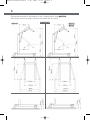
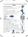
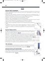
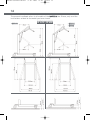
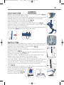
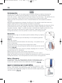
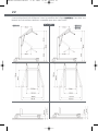
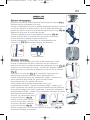
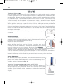
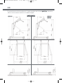
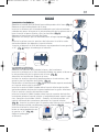
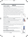
MANUALE SOLLEVA MALATI
31-01-2006
15:05
Pagina 1
SOLLEVATORI ELETTRICI E OLEODINAMICO
LIFTERS ELECTRIC AND OLEODYNAMIC
ÉLÉVATEURS ÉLETRIQUES ET OLÉODYNAMIQUE
LEVANTADORES ELÉCTRICOS Y OLEODIN ÀMICO
Mod. 71 - 08/2005
Pantone 7452C
Pantone 431C
.
.
.
.
Manuale di istruzioni
Instruction manual
Manuel d’instruction
Manual de instrucciones
Moretti S.p.A.
Fax +39 055 96 21 200
Via Bruxelles 3 - Meleto
www.morettispa.com
52022 Cavriglia (Arezzo)
[email protected]
Telefono +39 055 96 21 11
MANUALE SOLLEVA MALATI
31-01-2006
ITALIANO
ENGLISH
FRANCAIS
ESPANOL
15:05
Pagina 2
MANUALE SOLLEVA MALATI
31-01-2006
15:05
Pagina 3
Manuale di
Istruzioni
ITALIANO
MANUALE SOLLEVA MALATI
31-01-2006
15:05
Pagina 4
SOLLEVATORI
MODELLI: RP800 - RP805 - RP810
LEGGERE ATTENTAMENTE QUESTO MANUALE
PRIMA DELL’USO
INDICE
INTRODUZIONE.................................................................................................................... 5
DESTINAZIONE D’USO...................................................................................................... 5
DICHIARAZIONE DI CONFORMITÀ CE..................................................................... 5
MODELLI.................................................................................................................................... 5
DIMENSIONI............................................................................................................................ 6
MONTAGGIO............................................................................................................................. 7
USO.............................................................................................................................................. 8
PULIZIA...................................................................................................................................... 9
MANUTENZIONE................................................................................................................... 9
ACCESSORI............................................................................................................................ 10
GARANZIA.............................................................................................................................. 10
MANUALE SOLLEVA MALATI
31-01-2006
15:05
Pagina 5
5
INTRODUZIONE
Grazie per aver scelto un sollevatore della linea MOPEDIA by MORETTI.
Il loro design e la loro qualità garantiscono il massimo comfort, la massima sicurezza ed
affidabilità. I sollevatori MOPEDIA by MORETTI sono state progettati e realizzati per
soddisfare tutte le vostre esigenze per un corretto e pratico utilizzo. Questo manuale
d’uso contiene dei piccoli suggerimenti per un corretto uso dell’ausilio da voi scelto e dei
preziosi consigli per la vostra sicurezza. Si consiglia di leggere attentamente la totalità
del presente manuale prima di usare il sollevatore. In caso di dubbi la preghiamo di contattare il rivenditore, il quale saprà aiutarvi e consigliarvi correttamente.
DESTINAZIONE D’USO
I sollevatori della linea MOPEDIA sono destinati al sollevamento ed al trasferimento di
persone con difficoltà motorie, attraverso l’aiuto di un accompagnatore che aziona i
comandi. Non possono essere usati da una persona singola. La MORETTI S.p.A. declina
qualsiasi responsabilità su danni provocati da un uso improprio del dispositivo o da un
uso diverso da quanto indicato nel presente manuale.
DICHIARAZIONE DI CONFORMITA’ CE
La MORETTI S.p.A. dichiara sotto la sua esclusiva responsabilità che i prodotti fabbricati ed immessi in commercio dalla stessa MORETTI S.p.A. e facenti parte della famiglia
SOLLEVATORI
sono conformi alle disposizioni applicabili della direttiva 93/42/CEE sui DISPOSITIVI
MEDICI. A tal scopo la MORETTI S.p.A. garantisce e dichiara sotto la propria esclusiva
responsabilità quanto segue:
1. I dispositivi in oggetto soddisfano i requisiti essenziali richiesti dall’allegato I° della
direttiva 93/42/CEE come prescritto dall’allegato VII° della suddetta direttiva.
2. L’elenco completo dei dispositivi in oggetto viene indicato nell’Allegato A della pre
sente dichiarazione.
3. I dispositivi in oggetto NON SONO STRUMENTI DI MISURA.
4. I dispositivi in oggetto NON SONO DESTINATI AD INDAGINI CLINICHE.
5. I dispositivi in oggetto vengono commercializzati in confezione NON STERILE.
6. I dispositivi in oggetto sono da considerarsi come appartenenti alla classe I°.
7. NON E’ CONSENTITO utilizzare e/o installare i dispositivi in oggetto al di fuori della
destinazione d’uso prevista dalla MORETTI S.p.A.
8. La MORETTI S.p.A. mantiene e mette a disposizione delle Autorità Competenti la
documentazione tecnica comprovante la conformità alla Direttiva 93/42/CEE.
MODELLI
La linea di Sollevatori MOPEDIA by MORETTI è composta da tre diversi prodotti :
RP800 SOLLEVATORE OLEODINAMICO peso max paziente 150kg
RP805 SOLLEVATORE ELETTRICO peso max paziente 150kg
RP810 SOLLEVATORE ELETTRICO peso max paziente 180kg
MANUALE SOLLEVA MALATI
31-01-2006
15:05
Pagina 6
6
Il presente manuale fa riferimento a tutti i modelli della linea MOPEDIA.
Consultare solo le istruzioni relative al modello da voi scelto.
DIMENSIONI
• RP800
• RP805
• RP810
MANUALE SOLLEVA MALATI
31-01-2006
15:05
Pagina 7
7
MONTAGGIO
SOLLEVATORE OLEODINAMICO.
Rimuovere la molla di fissaggio dal perno bloccante della base. (Fig. 1)
Rimuovere il perno bloccante dalla base.
Inserire la colonna con la pompa oleodinamica nella base facendo
attenzione a porre il braccio nelle stessa direzione delle
gambe della base.
FIGURA
1
FIGURA
2
FIGURA
5
FIGURA
6
Inserire il perno fissante e fissare le viti. (Fig. 2)
Bloccare il perno con la molla di fissaggio.
Avvitare le maniglie per il movimento negli appositi inserti. (Fig. 3)
Inserire la leva per l’apertura della base nella relativa sede
facendo attenzione a bloccare la parte inferiore.
Inserire il bilanciere alla fine del braccio in corrispondenza del
gancio ad U. (Fig. 4) Appendere l’imbracatura al bilancino.
FIGURA
3
FIGURA
4
SOLLEVATORI ELETTRICI.
Rimuovere le viti di fissaggio dalla base e dalla colonna.
Inserire la colonna nella base facendo attenzione a porre il braccio
nella stessa direzione delle gambe della base. (Fig. 5)
Avvitare le viti di fissaggio della base.
Installare le maniglie come predisposto nella struttura e bloccarle
con le viti di fissaggio. (Fig. 6)
Svitare la vite centrale dalla staffa di supporto montata
nella parte esterna della colonna. (Fig. 7)
Inserire la centralina LINAK – Jumbo sulla parte inferiore della
staffa avendo cura di inserirla correttamente nelle guide inferiori.
Fissare la centralina attraverso la vite precedentemente tolta.
Inserire la batteria LINAK – Jumbo sulla parte superiore della
staffa, inserendo prima la parte inferiore e poi bloccando quella
superiore. Collegare l’attuatore LINAK – Jumbo ed il comando a
distanza alla centralina utilizzando i connettori presenti nella parte
inferiore. (Fig. 8) Inserire la leva per l’apertura della base nella
relativa sede facendo attenzione a bloccare la parte inferiore. (Fig. 9)
Inserire il bilanciere alla fine
del braccio in corrispondenza
del gancio ad U. (Fig. 10)
Appendere l’imbracatura
al bilancino.
FIGURA
8
FIGURA
9
FIGURA
FIGURA
10
7
MANUALE SOLLEVA MALATI
31-01-2006
15:05
Pagina 8
8
USO
SOLLEVATORE OLEODINAMICO.
Allargare le gambe della base fino alla massima ampiezza possibile prima di sollevare
tirando leggermente la leva di apertura verso di voi e bloccandola in una delle cinque
posizioni possibili.
Bloccare le ruote posteriori. Mantenere il paziente centrato tra le gambe della base – il
paziente deve essere rivolto verso chi lo assiste. Agganciare con cura le cinture dell’imbracatura al bilanciere. Assicurarsi che la valvola cilindrica sia chiusa.
Ruotare la valvola in senso orario verso la direzione “Closed”.
Azionare la leva di pompaggio per iniziare il sollevamento.
Sollevare il paziente all’altezza necessaria, mantenendolo in posizione frontale rispetto
a chi lo assiste. Sbloccare le ruote posteriori e trasferire il paziente.
Prima di iniziare la discesa del paziente bloccare le ruote posteriori.
Iniziare la discesa ruotando la valvola in senso antiorario verso la direzione
“Open”.
Per effettuare una discesa lenta ruotare leggermente la valvola, se volete
aumentare la velocità di discesa aprire maggiormente la valvola. Durante
la discesa, assistere il paziente per controllare la corretta posizione di
seduta.
FIGURA 11
SOLLEVATORE ELETTRICO.
Allargare le gambe della base fino alla massima ampiezza possibile prima
di sollevare tirando leggermente la leva di apertura verso di voi e bloccandola nella posizione di apertura (Fig. 11)
Bloccare le ruote posteriori. Mantenere il paziente centrato tra le gambe
della base – il paziente deve essere rivolto verso chi lo assiste. Agganciare
FIGURA 12
con cura le cinture dell’imbracatura al bilanciere. Azionare il sollevamento
attraverso il comando a distanza premendo il tasto (FRECCIA ALTO). (Fig. 12)
Sollevare il paziente all’altezza necessaria, mantenendolo in posizione frontale rispetto
a chi lo assiste. Sbloccare le ruote posteriori e trasferire il paziente.
Prima di iniziare la discesa del paziente bloccare le ruote posteriori. Iniziare la discesa
premendo il tasto (Freccia basso) sul comando a distanza. Durante la discesa, assistere
il paziente per controllare la corretta posizione di seduta.
Tasto emergenza.
I sollevatori elettrici sono dotati di un bottone di emergenza (tasto rosso)
che se premuto disattiva immediatamente tutti i comandi. Per ripristinare
il funzionamento ruotare in senso orario il tasto rosso. (Fig. 13)
FIGURA
13
FIGURA
14
Discesa emergenza (solo modello RP810).
Nel caso in cui si renda necessaria una discesa rapida del paziente agire
sullo sgancio rapido posizionato sul braccio meccanico sollevandolo. In
questo modo il paziente inizierà immediatamente la discesa senza agire
Fig. 14)
sul comando a distanza. (F
MANUALE SOLLEVA MALATI
31-01-2006
15:05
Pagina 9
9
ATTENZIONE
Il sollevatore elettrico è fornito di un sistema di sicurezza che arresta la discesa nel caso
in cui venga ostacolata. Si raccomanda di far risalire il paziente prima di togliere l’ostacolo per evitare cadute.
Ricarica della batteria. (Solo sollevatori elettrici.)
Le batterie dei sollevatori della linea MOPEDIA possono essere ricaricate attraverso il
caricabatteria in dotazione sia quando queste sono inserite nel sollevatore utilizzando la
connessione posta sotto la centralina di comando, sia staccando la batteria ed usando il
connettore presente. Durante la carica la luce “charge” è accesa. Quando il caricamento
è finito, la luce “charge” si spengerà automaticamente.
ATTENZIONE
Durante il normale funzionamento, quando la batteria è ad un 50%, il sistema di controllo emetterà un “beep” di avvertimento. In questo momento la batteria deve essere caricata immediatamente dopo aver terminato il trasferimento in corso.
Avvertenze:
• Il sollevatore è un dispositivo che permette di effettuare brevi trasferimenti di
un paziente con difficoltà di movimento come ad esempio da un letto ad una car
rozzina o una sedia comoda o viceversa. Il sollevatore non deve essere usato per
il trasporto del paziente.
• Durante il sollevamento del malato, assicurarsi che le gambe della base siano
aperte il più possibile ed i freni delle ruote posteriori siano bloccate.
• Durante il trasferimento evitate di oltrepassare ostacoli che potrebbero
provocare un ribaltamento.
• Verificate sempre il buon stato delle imbracature. Non usare imbracature che
presentino segni di danneggiamento o di usura.
PULIZIA
Per la pulizia delle imbracature utilizzare un soluzione di alcool e sapone neutro in parti
uguali miscelati con acqua.
MANUTENZIONE
E’ estremamente importante che il sollevatore sia controllato dopo ogni uso:
• In particolare si prega di controllare che tutte le viti e bulloni siano ben stretti.
• Che il sollevatore sia in grado di muoversi liberamente con i freni delle ruote
non attivi.
• Verificare i freni delle ruote posteriori per un corretto funzionamento.
• Verificare che il braccetto ad “U” e il gancio a “S” nella barra di ancoraggio siano ben
stretti.
Le parti meccaniche devono essere bagnati con un goccio di olio al fine di favorire la
MANUALE SOLLEVA MALATI
31-01-2006
15:05
Pagina 10
10
lubrificazione, in particolare fare attenzione ai punti:
• dove si connettono l’albero ed il braccetto, il gancio della barra di ancoraggio, la
cerniera della pompa manuale ed i semiassi della ruota
• dove si collegano la pompa ed il braccetto
• lubrificare come sopra indicato ogni due o tre mesi
ACCESSORI
Tutti i sollevatori della linea MOPEDIA sono compatibili con i seguenti accessori
Codice
RP820
RP822
RP824
RP826
Descrizione
IMBRACATURA STANDARD CON POGGIA TESTA
IMBRACATURA IMBOTTITA DELUXE
BILANCIERE PER IMBRACATURA STANDARD
BILANCIERE PER IMBRACATURA IMBOTTITA
Utilizzare solo accessori originali MORETTI.
In caso diverso si declina ogni responsabilità
su incidenti causati da un utilizzo improprio.
GARANZIA
Il prodotto è garantito 2 ANNI dalla data di acquisto. Il distributore si riserva il diritto di riparare o sostituire le parti affette da difetti di fabbricazione o nei materiali usati, senza nessuna spesa per il cliente. La garanzia non è applicabile in caso di danni legati ad un uso improprio, ad abusi, ad alterazioni o ad uno smontaggio effettuato da personale non autorizzato.
Per riparazioni, nel rispetto delle suddette condizioni per l’esercizio della garanzia, inviare il
prodotto munito della ricevuta di acquisto al rivenditore locale più vicino.
✁---------------------------------------------------------------------------------CERTIFICATO DI GARANZIA
APPARECCHIO TIPO___________________________________________________________________
ACQUISTATO IN DATA__________________________________________________________________
RIVENDITORE_______________________________________________________________________
VIA
___________________________________
LOCALITÀ
_________________________________________
VENDUTO A
________________________________________________________________________________
VIA
___________________________________
LOCALITÀ
_________________________________________
MANUALE SOLLEVA MALATI
31-01-2006
15:05
Pagina 11
Instruction Manual
ENGLISH
MANUALE SOLLEVA MALATI
31-01-2006
15:05
Pagina 12
LIFTERS
MODELS: RP800 - RP805 - RP810
READ THIS INSTRUCTION
MANUAL CAREFULLY BEFORE USE
INDEX
INTRODUCTION.................................................................................................................... 13
DESTINATION OF USE..................................................................................................... 13
DECLARATION OF CE CONFORMITY....................................................................... 13
MODELS.................................................................................................................................... 13
DIMENSIONS/SIZES.......................................................................................................... 14
ASSEMBLAGE...................................................................................................................... 15
USE..............................................................................................................................................16
CLEANING............................................................................................................................... 17
MAINTENANCE.................................................................................................................... 17
ACCESSORIES.......................................................................................................................18
GUARANTEE.......................................................................................................................... 18
MANUALE SOLLEVA MALATI
31-01-2006
15:05
Pagina 13
13
INTRODUCTION
Thank you for having chosen a lifter from the MOPEDIA line by MORETTI. Its design
and qualities guarantee the maximum comfort, the maximum safety and reliability.
The MOPEDIA lifters by MORETTI have been designed and made to satisfy all your
demands for a correct and practical use. This handbook gives you some little suggestions for a correct use of the device you have chosen and some useful advice for your
safety. We suggest you to read carefully the whole handbook before using your lifter. In
case of any doubt, please contact your retailer, who will be able to help you and give
you some correct advice.
DESTINATION OF USE
The lifters of the line MOPEDIA are made to lift and transfer people with difficulties in
movement, with the help of an attendant who operates the commands. They cannot
be used by a single person. MORETTI S.p.A. declines any responsibility for any damage caused by an improper use of the device or by a different use from that as suggested in the present handbook.
DECLARATION OF EC CONFORMITY
MORETTI S.p.A. declares under its exclusive responsibility that the products made and
put into the market by the same MORETTI S.p.A. , as part of the category of
LIFTERS
are in conformity with the applicable dispositions of the EEC DIRECTIVE
93/42 concerning MEDICAL DEVICES.
To such purpose MORETTI S.p.A. guarantees and declares under its own exclusive
responsibility what follows:
1.
The concerned devices meet the essential requisites as according to the 1°
enclosure of the directive 93/42/CEE as prescribed by the enclosure VII° of the
aforesaid directive.
2.
A complete list of the concerned devices is mentioned in the enclosure A of the
present declaration.
3.
The concerned devices ARE NOT INSTRUMENTS OF MEASURE.
4.
The concerned devices ARE NOT DESTINED FOR CLINICAL SURVEYS.
5.
The concerned devices are sold in a NON STERILE packing.
6.
The concerned devices are to be considered as belonging to the 1° class.
7.
Any use or installation of the concerned devices that differs from the destination
of use, as it is foreseen by MORETTI S.p.A., IS NOT ALLOWED.
8.
MORETTI S.p.A. keeps and makes available to the Competent Authorities the
technical documentation that proves the conformity to the EEC Directive 93/42.
MODELS
The line of Lifters MOPEDIA by MORETTI is composed of three different products:
RP800 OLEODYNAMIC LIFTER max. weight each patient 150kg
RP805 ELECTRIC LIFTER max. weight each patient 150kg
RP810 ELECTRIC LIFTER max. weight each patient 180kg
MANUALE SOLLEVA MALATI
31-01-2006
15:05
Pagina 14
14
The present handbook refers to all models of the MOPEDIA line. Please, only read the
instructions related to the model you have chosen.
DIMENSIONS/SIZES
• RP800
• RP805
• RP810
MANUALE SOLLEVA MALATI
31-01-2006
15:05
Pagina 15
15
ASSEMBLAGE
OLEODYNAMIC LIFTER.
Remove the fastening spring from the check pin of the base. (Fig. 1)
Release the check pin from the base.
Insert the mast with the oleodynamic pump into the mast sleeve and
carefully point the boom in the same direction as the base legs.
Insert the check pin and fix the screws. (Fig. 2)
Block the check pin with the fastening spring.
Screw the handles for movement into their proper place. (Fig. 3)
Insert the lever for the opening of the base into its correct place and
make sure to block the inferior part.
Attach the cradle at the end of the boom in correspondence of the Ushaped hook. (Fig. 4) Hang the sling to the cradle.
FIGURA
3
FIGURA
FIGURA
1
FIGURA
2
FIGURA
5
FIGURA
6
4
ELECTRIC LIFTERS.
Release the fastening screws away from the base and from the mast.
Insert the mast into the mast sleeve and make sure that the boom is
pointed in the same direction as the base legs. (Fig. 5)
Screw the fixing screws of the base.
Install the handles in their correct place and block them with the
fastening screws. (Fig. 6)
Release the central screw (Fig. 7) from the supporting bracket that is
fixed on the external side of the mast.
Insert the LINAK - Jumbo control box on the inferior part of the
bracket and ensure it correctly in the inferior slides.
Fix the control box with the screw previously removed.
Insert the LINAK - Jumbo battery on the superior part of the bracket,
first fixing the inferior part and then blocking the superior one.
Connect the LINAK - Jumbo actuator and the control handset to the
control box by using the connectors that are in the inferior
part. (Fig. 8)
Insert the lever for the opening of the base into its correct place and
make sure to block the inferior part. (Fig. 9)
Attach the cradle at the end of
the boom in correspondence
of the U-shaped hook. (Fig. 10)
Hang the sling to the cradle
FIGURA
8
FIGURA
9
FIGURA
FIGURA
10
7
MANUALE SOLLEVA MALATI
31-01-2006
15:05
Pagina 16
16
USE
Oleodynamic lifter.
Spread the base legs to the widest position before lifting by slightly throwing the
opening lever towards you and blocking it in one of the five possible positions.
Lock rear casters. Keep the patient centred between the base legs - the patient has to
face his attendant. Fasten with care the strings of the slings to the cradle
Make sure that the cylindrical valve is closed. Rotate the valve clockwise towards
“Closed”.
Operate the pumping lever to begin the lifting. Lift the patient up to the necessary
height, keeping him in frontal position towards his attendant.
Release the rear casters and transfer the patient. Before beginning the descent of the
patient lock the rear casters. Begin the descent by slightly rotating the valve anticlockwise towards “Open”. In order to make a slow descent slightly rotate the valve,
while if you want to increase the speed of descent open more the valve.
During the descent, assist the patient to attain correct sitting posture.
Electric lifter.
Spread the base legs to the widest position before lifting by slightly
pulling the
opening lever towards you and blocking it in the opening position
FIGURA 11
(Fig. 11)
Lock rear casters.
Keep the patient centred between the base legs - the patient has to
face his attendant.
Fasten with care the strings of the sling to the cradle
Operate the lifting by pressing the button (Arrow up) on the control
handset (Fig. 12)
Lift the patient up to the necessary height, keeping him in a frontal
FIGURA 12
position towards his attendant.
Release the rear casters and transfer the patient.
Before beginning the descent of the patient lock the rear casters.
Begin the descent by pressing the button (Arrow down) on the control handset.
During the descent, assist the patient to attain correct sitting posture.
Button of Emergency.
The electric lifters are endowed with a button of emergency (red
button) that , if pressed, immediately disarms all the commands. To
restore the operation rotate the red button clockwise. (Fig. 13)
Descent of emergency (only for model RP810).
When a rapid descent of the patient is necessary, operate a rapid
release and unhook the mechanical boom by lifting it. In this way
the patient will immediately begin the descent without operating the
control handset. (Fig. 14)
FIGURA
13
FIGURA
14
MANUALE SOLLEVA MALATI
31-01-2006
15:05
Pagina 17
17
ATTENTION
The electric lifter is provided with a safety device that stops the descent if there is any
obstacle. We recommend you to let the patient go up again before removing the obstacle so as to avoid any fall.
Recharge of the battery. (Only electric lifters.)
The batteries of the lifters of the MOPEDIA line can be recharged through the battery
charger supplied with, whether the batteries are inserted in the lifter by using the
connection that is under the control box, or by disconnecting the battery and using the
present connector. While recharging the light “charge” is on. When the loading is ended,
the light “charge” will automatically turn off.
ATTENTION
During a normal functioning, when the battery power is 50% low, the control system
will give “beep” warning. At this point the battery has to be immediately re-charged
after having finished the transfer in progress.
Warnings:
• The lifter is a device that allows short transfers of a patient with
difficulties in movement, as for example from a bed to a wheelchair or to a
commode or vice versa. The lifter must not be used to transport the patient.
• During the lifting of the patient, make sure that the base legs are in the
most widely opened position and that the brakes of the rear casters are
engaged.
• During the transfer do avoid to go against obstacles or the lifter
might tilt over.
• Always check that the slings are in a good state.
Don’t use slings that are damaged or worn out.
CLEANING
To clean slings use a solution of alcohol and neutral soap in equal parts mixed with
water.
MAINTENANCE
It is extremely important that the lifter is checked after every use:
• Particularly we recommend you to check that all screws and bolts are well tight.
• That the lifter can move freely with caster brakes off.
• Check the brakes of the rear casters for a proper operation
• Check that the “U”- shaped bracket at the end of the boom and the S-shaped hook
on the hanging bar are secured tightly
The mechanical parts have to be wet with a drop of oil for a better lubrication, particularly take care of the following areas:
MANUALE SOLLEVA MALATI
31-01-2006
15:05
Pagina 18
18
• Where the Mast and boom connect, the hanging bar hook , the pump handle hinge
and the caster axles.
• Where pump and boom attach.
• Lubricate as suggested above every two or three months
ACCESSORIES
All the lifters of the MOPEDIA line are compatible with the following accessories
Code
RP820
RP822
RP824
RP826
Description
STANDARD SLING WITH HEAD SUPPORT
DELUXE PADDED SLING
CRADLE FOR STANDARD SLING
CRADLE FOR PADDED SLING
Only use original accessories by MORETTI. In a different case we decline any
responsibility for any accident caused by an improper use.
GUARANTEE
This device has 2-YEAR warranty from the purchase date which is certified by the receipt or invoice. The distributor reserves the right either to repair or replace necessary parts to correct defects
in the materials or workmanship without any charge.
The warranty does not apply to damage resulting from failure to follow the operating instructions,
accidents, abuse, alteration or disassembly by unauthorized individuals.
In the case you need to get your device repaired and you fulfil the conditions of warranty, send the
device to the nearest retailer together with the purchase receipt.
✁---------------------------------------------------------------------------------WARRANTY CERTIFICATE
DEVICE MODEL______________________________________________________________________
PURCHASING DATE___________________________________________________________________
AUTHORIZED DEALER__________________________________________________________________
STREET
___________________________________
PLACE
_________________________________________
PURCHASED BY
________________________________________________________________________________
STREET
___________________________________
PLACE
_________________________________________
MANUALE SOLLEVA MALATI
31-01-2006
15:05
Pagina 19
Manuels
d’Instructions
FRANCAIS
MANUALE SOLLEVA MALATI
31-01-2006
15:05
Pagina 20
ÉLÉVATEURS
MODÈLES: RP800 - RP805 - RP810
PRIERE DE LIRE CE MANUEL D’ INSTRUCTIONS
ATTENTIVEMENT AVANT L’ USAGE
INDEX
INTRODUCTION................................................................................................................... 21
DESTINATION D’USAGE.................................................................................................. 21
DÉCLARATION DE CONFORMITÉ CE...................................................................... 21
MODÈLES................................................................................................................................ 21
DIMENSIONS........................................................................................................................ 22
ASSEMBLAGE...................................................................................................................... 23
USAGE...................................................................................................................................... 24
NETTOYAGE.......................................................................................................................... 25
ENTRETIEN........................................................................................................................... 25
ACCESSOIRES..................................................................................................................... 26
GARANTIE.............................................................................................................................. 26
MANUALE SOLLEVA MALATI
31-01-2006
15:05
Pagina 21
21
INTRODUCTION
Merci pour avoir choisi un élévateur de la ligne MOPEDIA by MORETTI. Leur design et
qualité garantissent le meilleur confort, la meilleure sûreté et fiabilité. Les élévateurs
MOPEDIA by MORETTI ont été projetés et réalisés pour satisfaire toutes vos exigences
et pour une jouissance correcte et pratique. Ce manuel d’usage contient des petites suggestions pour utiliser correctement le dispositif de secours/d’aide que vous avez choisi
et aussi quelques conseils précieux pour votre sûreté. Nous vous prions de lire attentivement et entièrement ce manuel avant d’utiliser l’élévateur. En cas de doutes nous
vous prions de contacter votre détaillant qui saura vous aider et vous conseiller correctement.
DESTINATION D’ USAGE
Les élévateurs de la ligne MOPEDIA sont destinés au soulèvement et au déplacement de
personnes avec difficultés de mouvements, à travers de l’aide d’un accompagnateur qui
actionne les commandes. Ce ne peut pas être utilisé par une personne toute seule.
MORETTI S.p.A décline chaque responsabilité sur les dégâts causés par un usage impropre du dispositif ou par un usage différent de celui-la comme indiqué dans le présent
manuel.
DÉCLARATION DE CONFORMITÉ CE
MORETTI S.p.A déclare sous sa responsabilité exclusive que les produits fabriqués et
vendus dans le commerce par MORETTI S.p.A , qui font part de la catégorie
ÉLÉVATEURS
sont conformes aux dispositions applicables de la directive 93/42/CEE sur les DISPOSITIFS MÉDICAUX. A tel but MORETTI S.p.A garantit et déclare sous sa propre responsabilité exclusive ce qui suit:
1. Les dispositifs en objet répondent à toutes les qualités essentielles demandées par
la pièce jointe I° de la directive 93/42/CEE comme prescrit par la pièce jointe VII°
de la directive susdite.
2. La liste complète des dispositifs en objet est indiquée dans la pièce jointe “A” de la
déclaration présente.
3. Les dispositifs en objet NE SONT PAS INSTRUMENTS DE MESURE.
4. Les dispositifs en objet ne sont pas DESTINÉS AUX ENQU TES CLINIQUES.
5. Les dispositifs en objet sont commercialisés dans un emballage PAS STÉRILE.
6. Les dispositifs en objet sont à considérer comme partie de la classe I°.
7. C’ EST INTERDIT d’utiliser et/ou bien d’installer les dispositifs en objet au delà de la
destination d’usage prévue par MORETTI S.p.A.
8. MORETTI S.p.A garde et met à la disposition des Autorités Compétentes la
documentation technique qui atteste la conformité à la Directive 93/42/CEE.
MODÈLES
La ligne d’Élévateurs MOPEDIA By MORETTI est composée de trois différents produits:
RP800 ÉLÉVATEUR OLÉODYNAMIQUE poids max chaque patient 150kg
RP805 ÉLÉVATEUR ÉLECTRIQUE poids max chaque patient 150kg
RP810 ÉLÉVATEUR ÉLECTRIQUE poids max chaque patient 180kg
MANUALE SOLLEVA MALATI
31-01-2006
15:05
Pagina 22
22
Le manuel présent fait référence à tous les modèles de la ligne MOPEDIA. Consultez seulement les instructions relatives au modèle que vous avez choisi.
• RP800
DIMENSIONS
• RP805
• RP810
MANUALE SOLLEVA MALATI
31-01-2006
15:05
Pagina 23
23
ASSEMBLAGE
Élévateur oléodynamique.
Enlevez le ressort de fixation du pivot de blocage de la base. (Fig. 1)
Enlevez le pivot de blocage de la base.
Insérez la colonne/le mât avec la pompe oléodynamique dans la base
en faisant attention à mettre le bras dans la même direction des
jambes de la base. Insérez le pivot de blocage et fixez les vis. (Fig. 2)
Bloquez le pivot avec le ressort de serrage.
Vissez les poignées pour le mouvement à leur place. (Fig. 3)
Insérez le levier pour l’ouverture de la base dans sa place en
faisant attention à bloquer la partie inférieure.
Insérez le balancier à la fin du bras en correspondance du
crochet à U. (Fig. 4) Accrochez l’élingue au palonnier.
FIGURA
3
FIGURA
FIGURA
1
FIGURA
2
FIGURA
5
FIGURA
6
4
Élévateurs électriques.
Enlevez les vis de fixation de la base et de la colonne/ du mât.
Insérez la colonne/le mât dans la base en faisant attention à
mettre le bras dans la même direction des jambes de la base. (Fig. 5)
Serrez les vis de fixation de la base. Installez les poignées comme
prédisposé dans la structure et bloquez-les avec les vis de fixation.
(Fig. 6)
Dévissez la vis centrale (Fig. 7) de la bride de support qui est
montée dans la partie extérieure de la colonne/du mât.
Insérez la boîte électrique des commandes LINAK - Jumbo sur la
partie inférieure de la bride, en ayant soin de l’insérer
correctement dans les guides inférieures.
Fixez la boîte électrique des commandes avec la vis
précédemment enlevée. Insérez la batterie LINAK - Jumbo sur la
partie supérieure de la bride, en insérant d’abord la partie inférieure
et ensuite en bloquant la partie supérieure. Connectez le dispositif
d’entraînement LINAK - Jumbos et le commande à distance à la boîte
électrique des commandes, en
utilisant les connecteurs dans
la partie inférieure. (Fig. 8)
Insérez le levier pour l’ouverture de la base dans sa place
en faisant attention à bloquer FIGURA 8
FIGURA 9
la partie inférieure. (Fig. 9)
Insérez le balancier à la fin du bras dans le crochet à U. (Fig. 10)
Accrochez l’élingue au palonnier.
FIGURA
FIGURA
10
7
MANUALE SOLLEVA MALATI
31-01-2006
15:05
Pagina 24
24
USAGE
Élévateur oléodynamique.
Étirez les jambes de la base jusqu’à obtenir l’ampleur plus grande possible avant de soulever
en tirant légèrement le levier d’ouverture vers vous et en la bloquant dans une des cinq positions possibles. Bloquez les roues postérieures. Gardez le patient en position centrale entre
les jambes de la base - le patient doit être tourné vers celui qui l’assiste. Accrochez avec soin
les ceintures de l’élingue au balancier. Assurez vous que la soupape cylindrique soit fermée.
Tournez la soupape en sens horaire vers le direction “Closed”. Actionnez le levier de pompage pour commencer le soulèvement. Soulevez le patient à l’hauteur nécessaire, en le gardant en position frontale par rapport à celui qui l’assiste. Débloquez les roues postérieures
et transférez le patient. Avant de commencer la descente du patient bloquez les roues postérieures. Commencez la descente en tournant la soupape en sens inverse aux aiguilles d’une
montre vers la direction “Open”. Pour effectuer une descente lente tournez la soupape légèrement, par contre si vous voulez augmenter la vitesse de descente ouvrez
encore plus la soupape.
Pendant la descente, assistez le patient pour contrôler sa correcte position
de séance
Élévateur électrique.
FIGURA 11
Étirez les jambes de la base jusqu’à obtenir la plus grande ampleur possible
avant de soulever en tirant légèrement le levier d’ouverture vers vous et en
la bloquant dans la position d’ouverture (Fig. 11)
Bloquez les roues postérieures.
Gardez le patient en position centrale entre les jambes de la base - le
patient doit être tourné vers celui qui l’assiste. Accrochez avec soin les
ceintures de l’élingue au balancier. Actionnez le soulèvement avec le comFIGURA 12
mande à distance en pressant la touche, Flèche vers l’haut, (Fig. 12)
Soulevez le patient à l’hauteur nécessaire, en le gardant en position frontale par rapport à
celui qui l’assiste. Débloquez les roues postérieures et transférez le patient.
Avant de commencer la descente du patient bloquez les roues postérieures. Commencer la
descente en pressant la touche, Flèche vers le bas, sur le commande à distance.
Pendant la descente, assistez le patient pour contrôler sa correcte position de séance
Bouton d’émergence.
Les élévateurs électriques sont dotés d’un bouton d’émergence (touche
rouge) qui désactive immédiatement tous les commandes, quand il est
pressé. Pour rétablir le fonctionnement tournez la touche rouge dans le
sens des aiguilles d’une montre (Fig. 13)
Descente d’émergence (uniquement pour le modèle RP810)
FIGURA 13
Quand une descente rapide du patient devient nécessaire, opérez sur le
décroche rapide qui est positionné dans le bras mécanique en le soulevant. De cette manière le patient commencera la descente immédiatement sans opérer sur le commande à distance.
(Fig. 14)
FIGURA
14
MANUALE SOLLEVA MALATI
31-01-2006
15:05
Pagina 25
25
ATTENTION
L’élévateur électrique est fourni d’un système de sûreté qui arrête la descente en cas
d’obstacles. On recommande de faire remonter le patient avant d’enlever l’obstacle pour
éviter des chutes.
Rechargement de la batterie. (Uniquement pour élévateurs électriques.)
Les batteries des élévateurs de la ligne MOPEDIA peuvent être rechargées avec le
recharge batterie en dotation, soit quand celles-ci sont insérées dans l’élévateur en utilisant la connexion au dessous du dispositif d’entraînement des commandes, soit en
débranchant la batterie et en utilisant le connecteur présent. Pendant la recharge la
lumière “charge” est allumée. Quand le rechargement est fini, la lumière “charge”
s’éteindra automatiquement.
ATTENTION
Pendant le normal fonctionnement, quand la batterie est chargée au 50%, le système
de contrôle émettra un “beep” d’avertissement. Dans ce moment la batterie doit être
rechargée immédiatement après avoir terminé le déplacement en cours.
Avertissements:
• L’élévateur est un dispositif qui permet d’effectuer des brefs déplacements d’un
patient avec difficultés de mouvement comme par exemple d’un lit à une voiture
d’infirme ou une chaise confortable ou vice versa. L’élévateur ne doit pas être
utilisé pour le transport du patient.
• Pendant le soulèvement du patient, assurez vous que les jambes de la base
soient ouvertes les plus possibles et que les freins des roues postérieures soient
bloqués.
• Pendant le déplacement évitez de dépasser des obstacles qui pourraient
provoquer un basculement.
• Vérifiez toujours le bon état des élingues. N’ utilisez pas des élingues qui
présentent signes d’endommagement ou d’usure.
NETTOYAGE
Pour le nettoyage des élingues utilisez une solution d’alcool et savon neutre en parties
égales mélangées avec de l’eau.
ENTRETIEN
C’est extrêmement important que l’élévateur soit contrôlé après chaque usage:
• Nous vous prions de contrôler en particulier.
• Que toutes les vis et boulons soient bien étroits. Que l’élévateur soit apte à se mouvoir
librement avec les freins des roues pas bloqués.
• Vérifiez les freins des roues postérieures pour un correct fonctionnement.
• Vérifiez que le petit bras à “U” et le crochet à “S” dans la barre d’ancrage soient bien
étroits.
Les parties mécaniques doivent être mouillées avec une goutte d’huile afin de favoriser
MANUALE SOLLEVA MALATI
31-01-2006
15:05
Pagina 26
26
le graissage, et en particulier il faut faire attention aux points suivants:
• le points de connexion de l’arbre/du mât et du petit bras, du crochet de la barre
d’ancrage, de la charnière de la pompe manuelle et des demi axes de la roue
• les points où la pompe et le petit bras se relient
• lubrifier comme selon indications chaque deux ou trois mois
ACCESSOIRES
Tous les élévateurs de la ligne MOPEDIA sont compatibles avec les accessoires suivants
Code
RP820
RP822
RP824
RP826
Description
ELINGUE STANDARD AVEC SUPPORT POUR LA T TE
ELINGUE REMBOURRÉE DELUXE
BALANCIER POUR ELINGUE STANDARD
BALANCIER POUR ELINGUE REMBOURRÉE
Utilisez uniquement les accessoires originaux MORETTI.
En cas différent on décline chaque responsabilité pour les accidents
causés par une jouissance impropre.
GARANTIE
Ce produit est accompagné d’une garantie de 2 ANS a partir de la date d’achat.
Le distributeur réserve le droit de réparer ou de remplacer les parties en défaut
de fabrication, sans aucun frais. Chaque modification, démontage non autorisé, abus,
mauvais emploi ou dommage accidentel va annuler cette garantie. Pour une éventuelle réparation, respectant les conditions citées, nous vous prions d’envoyer ce produit avec le ticket
d’achat au distributeur plus près.
✁---------------------------------------------------------------------------------CERTIFICAT DE GARANTIE
TYPE DE PRODUIT____________________________________________________________________
DATE D’ACHAT___________________________________________________________________
DISTRIBUTEUR__________________________________________________________________
RUE
___________________________________
LOCALITÉ
_________________________________________
VENDU À
________________________________________________________________________________
RUE
___________________________________
LOCALITÉ
_________________________________________
MANUALE SOLLEVA MALATI
31-01-2006
15:05
Pagina 27
27
Manuel de
Instrucciones
ESPANOL
MANUALE SOLLEVA MALATI
31-01-2006
15:05
Pagina 28
LEVANTADORES
MODELOS: RP800 -RP805-RP810
LEA CUIDADOSAMENTE ESTE MANUAL ANTES DEL USO
ÍNDICE
INTRODUCCIÓN..................................................................................................................... 29
DESTINO DE EMPLEO..........................................................................................................29
DECLARACIÓN DE CONFORMIDAD CE......................................................................29
MODELOS....................................................................................................................................29
DIMENSIONES..........................................................................................................................30
MONTAJE.....................................................................................................................................31
EMPLEO.......................................................................................................................................32
LIMPIEZA....................................................................................................................................33
MANTENIMIENTO...................................................................................................................33
ACCESORIOS........................................................................................................................... 34
GARANTÍA.................................................................................................................................34
MANUALE SOLLEVA MALATI
31-01-2006
15:05
Pagina 29
29
INTRODUCCIÓN
Gracias por haber elegido un levantador de la línea MOPEDIA by MORETTI. Su diseño
y su calidad garantizan el máximo comfort, la máxima seguridad y fiabilidad. Los
levantadores MOPEDIA by MORETTI han sido planeados y realizados para satisfacer
todas vuestras exigencias para un correcto y práctico empleo.
Este manual de empleo contiene pequeñas sugerencias para un correcto empleo del
auxilio elegido por vosotros y de valiosos consejos para vuestra seguridad.
Se aconseja leer cuidadosamente la totalidad del presente manual antes de usar el
levantador. En caso de dudas le rogamos contactar al detallista, que sabrá ayudarles y
aconsejarles correctamente.
DESTINO DE EMPLEO
Los levantadores de la lÌnea MOPEDIA estan destinados al levantamiento y al traslado
de personas con dificultades motoras, por medio de la ayuda de un acompañante que
acciona los mandos. No pueden ser usados por una persona individual.
La MORETTI S.p.A declina cualquier responsabilidad sobre daños provocados por un
empleo impropio del aparato o por un empleo diferente al indicado en el presente
manual.
DECLARACIÓN DE CONFORMIDAD
La MORETTI S.p.A declara bajo su exclusiva responsabilidad que los productos hechos
e introducidos en el comercio por la misma MORETTI S.p.A forman parte de la familia.
LEVANTADORES
Conformes a las disposiciones aplicables de la norma 93/42/CEE sobre los DISPOSITIVOS MÉDICOS. A tal objetivo la MORETTI S.p.A garantiza y declara bajo su propia y
exclusiva responsabilidad cuanto sigue:
1. Los aparatos en objeto satisfacen los requisitos esenciales requeridos por el
adjunto 1. de la norma 93/42/CCE prescrito en el adjunto VII° de la susodicha
norma.
2. La lista completa de los aparatos en objeto viene indicada en el Adjunto A de la
presente declaración.
3. Los aparatos en objeto NO SON INSTRUMENTOS DE MEDIDA.
4. Los aparatos en objeto no ESTÁN DESTINADOS A INVESTIGACIONES CLÍNICAS.
5. Los aparatos en objeto son comercializados en confecciones NO ESTÉRIL.
6. Los aparatos en objeto son considerados como miembros de la clase 1°.
7. NO SE PERMITE utilizar y/o instalar los aparatos en objeto fuera del destino de
empleo previsto por la MORETTI S.p.A.
8. La MORETTI S.p.A mantiene y pone a disposición de las Autoridades Competentes
la documentación técnica en conformidad a la Norma 93/42/CEE.
MODELOS
La lÌnea de Levantadores MOPEDIA by MORETTI está compuesta por tres diversos
productos: RP800 LEVANTADOR OLEODINÁMICO peso max cada paciente 150kg
RP805 LEVANTADOR ELÉCTRICO peso max cada paciente 150kg
RP810 LEVANTADOR ELÉCTRICO peso max cada paciente 180kg
MANUALE SOLLEVA MALATI
31-01-2006
15:05
Pagina 30
30
El presente manual hace referencia a todos modelos de la lìnea MOPEDIA. Consultar
sólo las instrucciones relativas al modelo elegido.
DIMENSIONES
• RP800
• RP805
• RP810
MANUALE SOLLEVA MALATI
31-01-2006
15:05
Pagina 31
31
MONTAJE
Levantador oleodinámico.
Remover el muelle de fijación del perno bloqueador de la base. (Fig. 1)
Remover el perno bloqueador de la base.
Insertar la columna con la bomba oleodinamica en la base teniendo
cuidado con poner el brazo en la misma dirección de las piernas de la
base. Insertar el perno fijante y fijar los tornillos. (Fig. 2)
Bloquear el perno con el muelle de fijado.
Atornillar las manijas para el movimiento en el lugar apropiado (Fig.
3)
Insertar la palanca para la apertura de la base en la relativa sede
teniendo cuidado con bloquear la parte inferior.
Insertar el balancín al final del brazo en correspondencia con gancho
a “U”. (Fig. 4) Colgar el embrague al balancÌn.
FIGURA
3
FIGURA
FIGURA
1
FIGURA
2
FIGURA
5
FIGURA
6
4
Levantadores eléctricos.
Remover los tornillos de fijado de la base y de la columna.
Insertar la columna en la base teniendo cuidado con poner el brazo en
la misma dirección de las piernas de la base. (Fig. 5)
Atornillar los tornillos de fijado de la base.
Instalar las manijas como está predispuesto en la estructura y bloquearlas con los tornillos de fijación. (Fig. 6)
Destornillar el tornillo central (Fig. 7) del estribo de soporte montado
en la parte externa de la columna.
Insertar la central LINAK-Jumbo sobre la parte inferior del estribo
teniendo cuidado de insertarla correctamente en las guÌas inferiores.
Fijar la central a través del tornillo sacado.
Insertar la batería LINAK-Jumbo sobre la parte superior del estribo,
insertando primero la parte inferior y luego bloqueando aquella superior. Conectar el actuador LINAK - Jumbo y el control remoto a la
central utilizando los conectores presentes en la parte inferior.
(Fig. 8) Insertar la palanca para la apertura de la base en la relativa
sede teniendo cuidado con bloquear la parte inferior. (Fig. 9)
Insertar el balancín al final del
brazo en correspondencia con
el gancho a “U”. (Fig. 10)
Colgar el embrague
al balancín.
FIGURA
8
FIGURA
9
FIGURA
FIGURA
10
7
MANUALE SOLLEVA MALATI
31-01-2006
15:05
Pagina 32
32
EMPLEO
Levantador oleodinámico.
Extender las piernas de la base hasta la máxima amplitud posible antes de levantar,
tirando ligeramente la palanca de apertura hacia vosotros y bloqueándola en una de
las cinco posiciones posibles.
Bloquear las ruedas posteriores. Mantener al paciente centrado entre las piernas de la
base -el paciente debe estar de frente a quien lo asiste.
Enganchar con cuidado los cinturones del embrague al balancÌn. Cerciorarse que la
válvula cilíndrica esté cerrada. Girar la válvula en sentido horario hacia la dirección
“Closed”. Accionar la palanca de bombeo para iniciar el levantamiento.
Levantar el paciente a la altura necesaria, manteniéndolo siempre en posición frontal
con respecto a quién lo asiste. Desbloquear las ruedas posteriores y trasladar al
paciente. Antes de iniciar el descenso del paciente bloquear las ruedas posteriores.
Iniciar el descenso girando la válvula en sentido contrario a las agujas del reloj, hacia
la dirección “Open”. Para efectuar una bajada lenta girar ligeramente la
válvula, si desea aumentar la velocidad de bajada, abrir más la válvula.
Durante la bajada, asistir al paciente para controlar que esté sentado
correctamente.
Levantador eléctrico.
FIGURA 11
Extender las piernas de la base hasta la máxima amplitud posible antes
de levantar, tirando ligeramente la palanca de apertura hacia vosotros y
bloqueándola en la posición de apertura (Fig. 11)
Bloquear las ruedas posteriores. Mantener al paciente centrado entre las
piernas de la base -el paciente tiene que estar de frente a quien lo asiste.
Enganchar con cuidado los cinturones del embrague al balancÌn.
Accionar el levantamiento por medio del control remoto presionando la
FIGURA 12
tecla (Flecha alto). (Fig. 12)
Levantar el paciente a la altura necesaria, manteniéndolo en posición frontal con
respecto a quién lo asiste.
Desbloquear las ruedas posteriores y trasladar al paciente. Antes de iniciar la bajada
del paciente bloquear las ruedas posteriores. Iniciar la bajada presionando la tecla
(Flecha bajo) en el control remoto. Durante la bajada, asistir al paciente con el fin de
controlar que esté sentado correctamente.
Tecla de emergencia.
Los levantadores eléctricos están dotados de un botón de emergencia
(tecla roja) que si se presiona desactiva enseguida todos los
mandos.Para restablecer el funcionamiento girar en sentido horario la
tecla roja. (Fig. 13)
FIGURA
13
FIGURA
14
Bajada de emergencia (solo modelo RP810).
En el caso en que se haga necesaria una bajada rápida del paciente
levantar el desengancho rápido situado sobre el brazo mecánico. De
esta forma el paciente iniciará inmediatamente la bajada sin tener que
utilizar el control remoto. (Fig. 14)
MANUALE SOLLEVA MALATI
31-01-2006
15:05
Pagina 33
33
ATENCIÓN
El levantador eléctrico está provisto de un sistema de seguridad que detiene la bajada
en el caso que sea obstaculizada.
Se recomienda hacer subir de nuevo al paciente antes de sacar el obstáculo para evitar caídas.
Recarga del bateria (solo levantadores eléctricos).
Las baterías de los levantadores de la lÌnea MOPEDIA puede ser recargadas por medio
del cargador de batería proporcionado, sea cuando se insertan las baterias en el levantador utilizando la conexión ubicada bajo la central de mando, o sea despegando la
baterÌa y usando el conector presente. Durante la carga la luz “charge” se mantendrá
encendida. Cuando la bateria está cargada, la luz “charge” se apagará automáticamente.
ATENCIÓN
Durante el funcionamiento normal, cuando la baterÌa está a un 50%, el sistema de
control emitirá un “beep” de advertencia.En este momento la baterÌa tiene que ser
cargada inmediatamente después de haber acabado el traslado en curso.
Advertencias:
• El levantador es un aparato que permite efectuar breves traslados de un
paciente con dificultad de movimiento, como por ejemplo de una cama a una
silla de ruedas o una silla cómoda o viceversa. El levantador no debe ser
usado para el transporte del paciente.
• Durante el levantamiento del enfermo, cerciorarse que las piernas de la base
esten abiertas al máximo posible y los frenos de las ruedas posteriores estén
bloqueados.
• Durante el traslado evitar superar obstáculos que pudieran
provocar un vuelco.
• Verificar siempre el buen estado de los embragues. No usar embragues que
presenten señales de daño o desgaste.
LIMPIEZA
Para la limpieza de los embragues utilizar una solución de alcohol y jabón neutro en
partes iguales mezclados con agua.
MANTENIMIENTO
Es extremadamente importante que el levantador sea controlado después de cada
empleo:
• En particular se ruega controlar que todos los tornillos y pernos esten bien ajustados
• Que el levantador sea capaz de moverse libremente aún cuando los frenos de las
ruedas no esten activados
• Verificar los frenos de las ruedas posteriores para un correcto funcionamiento.
• Verificar que la abrazadera a “U” y el gancho a “S” estén bien ajustados en la barra
de anclaje.
MANUALE SOLLEVA MALATI
31-01-2006
15:05
Pagina 34
34
Las partes mecánicas tienen que ser humedecidas con una gota de aceite para favorecer la lubricación, en particular tener cuidado a los siguientes puntos:
• donde se conectan el árbol y la abrazadera, el gancho de la barra de anclaje,
la cremallera de la bomba manual y los semiejes de la rueda
• donde se enlazan la bomba y la abrazadera lubricar como se ha indicado
anteriormente cada dos o tres meses
ACCESORIOS
Todos los levantadores de la línea MOPEDIA son compatibles con los siguientes
accesorios:
Código
RP820
RP822
RP824
RP826
Descripción
EMBRAGUE ESTÁNDAR CON APOYA CABEZA
EMBRAGUE ACOLCHADO DELUXE
BALANCINES PARA EMBRAGUE ESTÁNDAR
BALANCÍN PARA EMBRAGUE ACOLCHADO
Sólo utilizar accesorios originales MORETTI. De lo contrario se declina cualquier
responsabilidad sobre accidentes causados por un empleo inapropiado.
GARANTÍA
Este producto está garantizado por 2 AÑOS a partir de la fecha de compra. El distribuidor tiene
el derecho de decidirse por la reparación o la substitución de la unidad o parte con defectos de
fabricación o hecha de material defectuoso, sin gastos por el comprador. Esta garantía no es válida si el producto es sometido a malos tratos o abusos, o si es desmontado por personal no autorizado. Por las reparaciones que correspondan a las condiciones sobredichas, enviar el producto
con el comprobante de compra al distribuidor local más cercano.
✁---------------------------------------------------------------------------------CERTIFICACION DE GARANTIA
MODELO___________________________________________________________________________
FECHA DE COMPRA___________________________________________________________________
REVENDEDOR__________________________________________________________________
CALLE
___________________________________
CIUDAD
_________________________________________
VENDIDO A
________________________________________________________________________________
CALLE
___________________________________
CIUDAD
_________________________________________
MANUALE SOLLEVA MALATI
31-01-2006
15:05
Pagina 35
Fabbricante / Manufacturer by:
MORETTI S.p.A. Via Bruxelles 3
52022 Loc.Meleto Cavriglia AREZZO - Italy
www.morettispa.com [email protected]
Made in Taiwan
Mod. 71 - 08/2005
MANUALE SOLLEVA MALATI
31-01-2006
15:05
Pagina 36