1
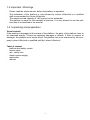
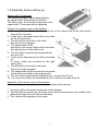
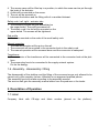
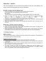
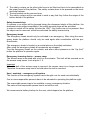
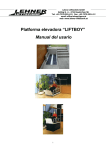
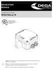
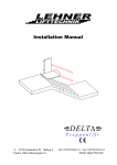
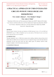
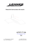
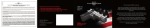
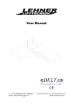
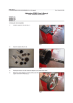
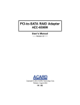
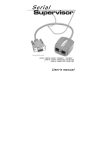
User Manual
A – 4724 Neukirchen/W, Salling 8
Email: [email protected]
Web: www.lehner-lifttechnik.at
Tel: 07278/3514-15, Fax: 07278/3514-12
Mobil: 0664/3526190
Tabel of contents
1. In general....................................................................................2
1.1.Producer ...................................................................................2
1.2.Utilisation ...................................................................................2
1.3.Important / Warnings.................................................................3
1.4.Unpacking and preparation ......................................................3
1.5.Assembly before starting up ....................................................4
1.6.Assembly - disassembly / fitting..............................................5
2. Describtion of Operation ..........................................................5
1.1 Label ...........................................................................................5
1.2 Safety function...........................................................................6
3. Demontage & Transport............................................................8
3.1 Transport ....................................................................................8
3.2 Packing during the transport ...................................................8
4. Attendance and keeping ...........................................................8
4.1 Cleaning......................................................................................8
4.2 Keeping and storage .................................................................8
4.3 How to prevent corrosion? .......................................................8
4.4 Which attendance has to be made by the owner? .................8
5. Attendance & durabilityr ...........................................................8
5.1 Durability and attendance.........................................................8
5.2 Fuses ..........................................................................................9
5.3 Assessment – Alround..............................................................9
5.4 Error search .............................................................................10
6. Technical data..........................................................................11
Platform Typ 1..................................................................... 11
Platform Typ 2..................................................................... 11
1. In general
1.1.
Producer
Fa. Lehner Lifttechnik G.m.b.H.
A – 4724 Neulirchen am Walde, Salling 8
Tel: +43.7278.3514-15, Fax: +43.7278.3514-12
Mobil: 0664/3526190, E-mail: [email protected]
www.lehner-lifttechnik.at
1.2.Utilisation
Utilisation
The platform is produced for the utilisation inside and outside. The platform can be used
at temperatures of -20 up to + 40° C. At temperatures under – 20° C we recommend the
warming of the platform.
The platform is made for disabled persons, who have to do height differences of 835
mm (1-6 stairs)
It is possible to drive in and drive out of the platform on every side. In order to protect
the user of the platform from falling of the platform the platform is equipped with a safety
rail on both sides. In order to protect the upper stop there is a rail which drives with the
lift.
It is necessary to instruct the users and the assistants carefully.
2
1.3.Important / Warnings
-
-
Please read the whole manual, before the platform is operated
The installation of the platform is only allowed by Lehner Lifttechnik or a qualified
staff recommended by Lehner Lifttechnik.
The maximum load capacity of 180 kg must not be exceeded.
The platform is made for the transport of persons, it is only allowed to use the platform how it is described in the manual.
1.4. Unpacking and preparation
Visual controlI:
If the packing is damaged at the receipt of the platform, the parts of the platform have to
be examined exactly, if there are apparent damages or defects. If there is suspect of
damages, the platform must not be used! The platform has to be examined by the company Lehner Lifttechnik or qualified staff by Lehner Lifttechnik.
Tabel of content
platform and safety curtain
access ramp
rail / safety curb
electric power supply
application
manual
3
1.5.Assembly before starting up
Safety curb 1 rail actuator
The assembly screws are pre-assembled on
the upper board. They will be screwed off.
The safety curb / the rail will be mounted on the
upper board. The screws will be tightened.
Fixing of the access ramp on the platform
1. Screws, disks, bush, screw nuts which are on the swivel joint of the side access
ramp will be removed.
2. A disk and a lubricated bush will be mounted
on the let swivel joint.
3. The disk will be mounted on the bush.
She must not be clamped.
4. The second disk will be
mounted on the screw, which will be mounted
through the bore of the safety curb.
5. The nut will be mounted and screwed down
but not so fix.
6. A disk and a lubricated bush will be mounted
on
te screw, which are mounted on the right
swivel joint.
7. The disk will be mounted on the bush,
She must not be clamped.
8. The second disk will be mounted on the screw,
which will be mounted on the angle profile
9. The nut will be mounted and screwed down – screw it that it is fix.
10. The nut on the safety cub (described in point 5) will be screwed down fix.
Assembly of the access ramp of the actuator
Attention: Single components are correctly mounted at the delivery.
1. The bush will be lubricated and placed on the actuator.
2. The disk will be mounted on the screw, which will be mounted from the middle of the
platform through the eye of the access ramp.
3. The 3 disks will be placed on the screw.
4
4. The access ramp will be lifted up in a position, in which the screw can be put through
the bush of the actuator.
5. A disk will be mounted on the screw.
6. The nut will be screwed on.
7. Lubricate the bottom and the fitting with oil or another lubricant.
Safety curb / rail, right – actuator side
1. The assembly screws are pre-assembled on
the upper board. They will be screwed off.
2. The safety curb / the rail will be mounted on the
upper board. The screws will be tightened.
End profile
1. Has to be mounted on the ends of the small safety curb.
Manual operation
The manual operation will be put on the rail.
1. The connector will be mounted in the connector bush in the safety curb.
2. The manual operation will be screwed down and the connector is waterproof.
Transformer
1. The connector of the transformer will be connected to the connector back at the platform.
2. The power plug has to be connected to the supply network system.
Put on the energy.
1.6. Assembly - disassembly / fitting
The disassembly of the platform and the fitting of the accessories are only allowed to be
carried out by the company Lehner Lifttechnik or an approved qualified person.
The assembly has to be made according to the assembly manual.
The service staff gets the assembly manual either from the producer or the trader.
2. Describtion of Operation
1.1 Label
Company label with CE-sign and fabric number (placed on the platform).
5
Operation – electric
The manual operation can be mounted at the platform by the user of the platform. Operation buttons and the symbols are easy to understand.
Up (Auf)- function, from the bottom level
1. When the platform is on the bottom level and the access ramp is
on the same level, the wheelchair user can drive on
the platform.
The rail that goes up with the platform is used as safety rail for the upper stop.
2. When you press the button „Up (AUF)“ the access ramp drives upstairs and takes
over
the
function
of
the
safety
rail.
“Up (AUF)” is not active as long as the button won´t be pressed.
3. If the access ramp/safety rail is in the upper position and “Up (AUF)” will be pressed
furthermore, the platform moves upstairs.
4. When the platform has reached the passage the wheelchair user can drive on the
passage.
Down (Ab) – function, from the top level
1. The wheelchair user dirves on the platform.
2. When you press the button "Down (AB)" the platform drives down. As long as the
button is pressed this function is active.
3. When the platform has reached the level and the button is still pressed, the access
ramp/safety rail will be lowered and the wheelchair user can leave the platform.
1.2 Safety function
Safety curtains
The pre-assembled safety curtains ensure that nobody will be jammed, if the platform is
in the highest position and drives down.
Assembly and safety curtains
1. The areas of the safety curtains are pre-assembled with chain belts.
2. A broomstick or something similar should be placed on the narrow side of the shear
construction.
3. The safety curtains have to be put over the upper board and have to be placed on
the broomstick, so that they hover freely.
4. The safety curtains are lifted and assembled. Always start with the angles in the
other side of the access ramp on the upper board of the platform. The safety curtains
have to be pressed on the hook-and-loop tape fastener.
6
5. The safety curtains on the other side have to be lifted and have to be assembled on
the upper board of the platform. The safety curtains have to be pressed on the hookand-loop fastener.
6. The broomstick can be removed now.
7. The safety curtains will be mounted in such a way that they follow the edges of the
bottom board of the platform.
Safety terminal strip
If a person or an object will be jammed during the downward stroke of the platform, the
downward stroke stops immediately if the safety terminal strips will be activated.
In order to switch off the safety function the “AUF” (Up) button has to be pressed. Now
the object can be removed, which has activated the safety terminal strip.
Emergency break
The emergency break should only be activated in an emergency. After using the emergency break the platform should only be used again after consultation with the producer/trader.
The emergency break is located on a central place on the safety curbstone.
After using the emergency break all movements are stopped.
Turn the emergency break on the outside, and after a short pressure on the “Up (Auf)”
button the platform is operative again.
Emergency lowering device – access ramp
The access ramp is mounted with a bolt on the actuator. This bolt will be screwed on an
the access ramp opens. Look at point 1. 5.
Important
When the bolt of the access ramp is removed, the access ramp is no longer mounted.
Therefore the access ramp has to be held when the bolt is removed.
User / assistant – emergency call system
The function of the emergency system has to thought over for each use individually.
One or more responsible person/s have to be educated in operating the platform right.
The responsible person has to be available in every emergency situation.
The name of the responsible person has to be told the user.
We recommend a battery backup for the user, which depend on the platform.
7
3. Disassambly & Transport
3.1 Transport
It is possible to deconstruct the platfform for the transport and the keeping, platform,
band, ramp.
3.2 Packing during the transport
The company Lehner Lifttechnik recommends to transport the platform in the original
packing.
4. Attendance and keeping
4.1 Cleaning
The lifting platform can be cleaned with a sponge or a brush and soap water.
The lifting platform can be hosed down with a normal water pressure, but not with a
pressure washer.
Acid, base or solvent may not be used for cleaning
4.2 Keeping and storage
No special requirements.
4.3 How to prevent corrosion?
The lifting platform is made out of corrosion-resist materials and therefore no corrosion
protection is necessary.
4.4 Which attendance has to be made by the owner?
Cleaning on demand.
5. Attendance & durability
5.1 Durability and attendance
The platform has to be undergone an attendance at least once a year due to the national law.
The platform has a durability of about 10 years with regular, daily use. After this period
the lifting platform has to be assessed by specialized staff in order to evaluate the further application.
8
The durability is based to the conventional use, a regular cleaning as well as attendance
and an annual assessment of specialized staff or the company Lehner Lifttechnik
GmbH.
Spare-part lists and drawings can be requested at the producer or the trader.
5.2 Fuses
If a fuse drops out, the cause has to be examined by qualified staff. The exchange of the
fuse is only allowed by qualified staff, before the platform is operating again.
5.3 Assessment – Allround
With the Attendance it has to be recorded what has been examined and exchanged.
Parts which show abrasion or damages have to be replaced with new original parts.
1. Visual control of the product
Control, if abrasion can be diagnosed.
Control if the product has deformations.
Control if the product has other forms of damages.
2. Examination of the product during the normal utilization
All functions of the products with our without burden.
Control emergency lowering device on proper function.
Control voltage index on proper function.
3. Control of the electrical situation of the product.
Control cable bushing.
Control connection and plug.
Control controler unit.
4. Control of the mechanic condition of the product
Remove dirt and other uncleanliness.
Maintenance and assessment of the vital parts of the product.
Lubricate the product.
5. Point 2: repeat control, that everything is working properly.
Were there new problems in Point 5.
If new problems emerge, go back to point 2.
If no problems were discovered; you can finish the Attendance.
9
5.4 Error search
1. Is the connector from the electric power supply put into the outlet?
Put the connector into the outlet.
2. Is the outlet switch on?
Turn the outlet switch on.
3. Electric power supply there? Maybe the fuse is damaged?
Control the fuses and exchange them if necessary.
4. Is the emergency connection on?
Release/ disconnect the emergency connection through turning the button until it
jumps out.
5. The platform can´t drive upwards but not downwards?
Remove impurities on the securtiy band. Control the security band if there are
other obstacles.
6. Is the connector connection between the electric power supply and the platform
made?
Put the connector on.
Call the company Lehner Lifttechnik, if you can not solve the above mentioned defects.
10
6. Technical data
Platform Typ 1
maximum height of stroke.................................................................................. 600 mm
load capacity .........................................................................................................180 kg
lifting speed .......................................................................................................10 mm/s
minimum height (headroom).............................................................................. 110 mm
weight...................................................................................................................52,5 kg
electric power supply ........................................ 24 V through transformer on 230 V grid
Inside dimension (length) ................................................................................ 1170 mm
Inside dimension (breadth) ............................................................................... 710 mm
Outside dimension (length) ............................................................................. 1180 mm
Outside dimesnion (breadth) ............................................................................ 810 mm
Platform Typ 2
maximum height of stroke.................................................................................. 830 mm
load capacity ........................................................................................................180 kg
lifting speed........................................................................................................10 mm/s
minimum height (headroom) ............................................................................. 120 mm
weight ..................................................................................................................71,5 kg
electric power supply ........................................ 24 V through transformer on 230 V grid
inside dimension (length) ................................................................................ 1495 mm
inside dimension (breadth) ............................................................................... 785 mm
outside dimension (length) .............................................................................. 1505 mm
outside dimension (breadth) ............................................................................. 890 mm
Warranty .............................................................................................................. 1 year
In many situations it is necessary to make a special adaptation of the platform, whereas
the above mentioned specifications can change.
11