1
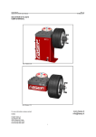
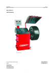
FASEP 2000 srl
F:\DOCUMENT\SERVICE\TECH_DOC\WB\B2000_12_to_20c_ing.wpd
Rev. 1 March 12, 2003
Addendum B2000 User’s Manual
From 1.20 version to 2.0c version
VERSION 2.0c
VERSION 2.0b
VERSION 2.0a
VERSION 2.0
1. Placing the wheel (only B201)
1.1
Install the support on the shaft (Fig. 1)
Fig. 1
1.2
Select the adaptors (Fig. 2 e 3).
Fig. 2
Fig. 3
1.3
Placing the wheel on the shaft: select the adaptors to put outside of the wheel.
1.4
Select the correct adaptors to install until the end of the
support. and lock the wheel (Fig. 4)
Fig. 4
FASEP 2000 srl
F:\DOCUMENT\SERVICE\TECH_DOC\WB\B2000_12_to_20c_ing.wpd
Rev. 1 March 12, 2003
2. Input of rim dimesnion (only B201)
2.1
INPUT OF DIAMETER
See the 5.4a.1 of the User’s Manual
2.2
INPUT OF WIDTH
Put the rod on the inside of the rim (Fig. 5). See the value of the distance on the graduated scal on the rod (Fig. 6). See
the 5.4a.2a of the User’s Manual to insert the distance.
Fig. 6
Fig. 5
2.3
INPUT OF THE WIDTH
Measure the value of the width with the width gauge (Fig. 7).
(see on the User’s Manual)
Fig. 7
FASEP 2000 srl
F:\DOCUMENT\SERVICE\TECH_DOC\WB\B2000_12_to_20c_ing.wpd
Rev. 1 March 12, 2003
3. Calibration (only B201)
3.1
Place a wheel, most balance as it possible, on the flange (see the chpater 1 of the addendum for placing of the wheel)
3.2
Switch on the wheel balancer; SOF X.XX (software version).is displayed .Before it is off, push <SET>;appears CAL on
the left display.
3.3
Press <SET> to entry in the program for the calibration of sensors; appears In on the left display and the default value
for distance on the right display.
3.4
Input the distance as at 2.2 of the addendum. Press <SET>, diA appears on the left display and the default value of
diameter on the right.
3.5
Input the diameter as at 2.1 of the addendum. Press <SET>, C1 appears on the left display.
3.6
Start the wheel (unclockwise spin).
J
ADVICES:
G
NOTE:
Using the standard tooluntil the correct speed of the wheel.
During the spin Acc El, rEd UCE or Go od appears on the display to indicate that you
have to accelerate, reduce the speed or that it’s ok.
Also the leds of the display indicate the good speed: when all are light on, the speed is
ok.
Err 19 appears if the speed is not good before of 4" after the start. Then St oP blinks
after that a new start is required after stop the wheel.
3.7
The display shows from 5 to 0 when the speed decrease. When St oP blink, lock the wheel. tu rn appears on the
display.
3.8
Turn the wheel until 60 Put appears on the display. Put 60grs adhesive weight on inside (see 6.7.4 on the User’s
Manual).
3.9
Press <SET>; C2 appears on the left display.
G
NOTE:
Press <SET> when the wheel is lock into the position of 60grs weight is required. nothing
happens if press <SET> in different position.
3.10
See the 3.6 for the second run.
3.11
The display shows from 5 to 0 when the speed decrease. When St oP blink, lock the wheel. ST OP appears on the
display.
3.12
Press <ESC> to escape from calibration procedure.
FASEP 2000 srl
F:\DOCUMENT\SERVICE\TECH_DOC\WB\B2000_12_to_20c_ing.wpd
Rev. 1 March 12, 2003
4.
MEASUREMENT AND CORRECTION OF IMBALANCE (only B201)
4.1
Place the wheel rim on the shaft, paying attention to the position of the pin or bolts according to each case (see the
chapter 1 of the addendumfor assembling wheel).
4.2
Insert details of the wheel (see chapter 2 of the addendum).
4.3
Start the wheel. The wheel has to be run unclockwise.
J
ADVICES:
G
NOTE:
Using the standard tooluntil the correct speed of the wheel.
During the spin Acc El, rEd UCE or Go od appears on the display to indicate that you
have to accelerate, reduce the speed or that it’s ok.
Also the leds of the display indicate the good speed: when all are light on, the speed is
ok.
Err 19 appears if the speed is not good before of 4" after the start. Then St oP blinks
after that a new start is required after stop the wheel.
4.4
When St oP blink, lock the wheel.
4.5
See 6.7.4 of User’s Manual to apply the weight.