1
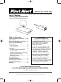
Model No.: FAW-620
User’s Manual
2.4 GHz Wireless Color Monitoring System
• Receiver with Patch Antenna
• Camera With Patch Antenna
Table of Contents
Important Safety Precautions . . .IFC
Specifications . . . . . . . . . . . . . . . . . .1
Parts Included With This System . . .2
Wireless Color Monitoring
System Parts . . . . . . . . . . . . . . . . . .2
Parts of Camera . . . . . . . . . . . . . . .2
Parts of Receiver . . . . . . . . . . . . . .2
Installation . . . . . . . . . . . . . . . . . . . .3
Installing the Mounting Bracket
(Camera Stand) . . . . . . . . . . . . . . .3
Installing and Aligning the Mounting
Bracket (Camera Stand) . . . . . . . . .3
Installing the Wireless Color
Monitoring System . . . . . . . . . . . . .4
Rotating Antennas
for Best Performance . . . . . . . . . . . .5
Auto-Sequence Function . . . . . . . . .5
Troubleshooting Guide . . . . . . . . . . .6
Warranty . . . . . . . . . . . . . . . . . . . . . .6
IMPORTANT!
Read this carefully before
installing or using these units.
DANGER-HIGH VOLTAGE–Unit should
only be opened by an authorized
technician if service is required.
Safety Precautions
For correct and safe operation of this
system it is essential installers, endusers and service technicians follow all
safety procedures outlined in this manual. Specific Warning and Caution
statements (and/or symbols) are
marked on the units where needed.
Warning and Caution Statements
“WARNING” indicates a situation
where failure to follow proper procedures can cause personal injury.
“CAUTION” indicates a situation where
failure to follow proper procedures can
cause damage to the equipment.
PLEASE READ CAREFULLY AND SAVE
This manual contains important information about this product’s operation.
If you are installing this product for use by others you must leave this manual –
or a copy – with the end user.
First Alert® is a registered trademark of The First Alert Trust, Inc. used under license.
Important Safety Precautions
Please read before installing
Congratulations on your purchase of the 2.4 GHz Wireless Color Monitoring System. Please
read these safety and operating instructions carefully before installing and using this system.
• Keep the camera, receiver and adapter cord out of reach of children.
• Do not place the camera, receiver or adapter cord in a crib or playpen.
• Do not use camera near water or damp and wet environments, such as a bathtub,
laundry tub, kitchen sink, or wet basements.
• Locate the camera, receiver and AC adapter where there is adequate ventilation. Do
not locate the camera in direct sunlight.
• Do not locate the camera, receiver and AC/DC adapter near heat sources such as
heat registers, radiators, ovens, furnaces or other appliances with high operating
temperatures.
• Do not use with extension cords. Use only the AC/DC adapter provided with this
system. Use of other adapters may damage the camera and void your warranty.
• Only plug components into standard household voltage outlets (120V AC, 60 Hz).
• Do not place cords from the AC adapter, camera or receiver where they can be
pinched or stepped on. Protect the cords by keeping them out of the way of
children, pets and routine household traffic. Do not place heavy objects on power
cords or cover cords with rugs or carpet.
• When cleaning, use a DRY, lint-free cloth. Unplug the camera, receiver, and AC adapter
before cleaning. NEVER immerse any component in water and do not spray cleaners
or solvents on the unit. Doing so may damage the unit or cause electrical shock.
• Unplug the AC adapter from the wall outlet when the system is not in use.
• Mishandling, alterations or modifications not approved by the manufacturer will void
the warranty.
Connect this unit ONLY to other compatible units. Do not connect it to any other type of
alarm or auxiliary device. Connecting anything else to this unit may damage it or prevent
it from operating properly.
Do not paint over the camera.
This system uses public airwaves for wireless operation. The sound and video may be
broadcast to and picked up by other 2.4 GHz receiving devices. Conversations and
images from other rooms near the camera may be broadcast and picked up. To protect
your privacy, always turn the camera off when not in use. JJC, Inc. shall not be
liable for any misuse or use contrary to local, state, or federal laws.
(IFC)
FCC WARNING
This equipment generates and uses radio frequency energy and if not installed and used
properly, that is, in strict accordance with the manufacturer’s instructions, may cause
interference to radio and television reception. It has been tested and found to comply
with the limits for a Class B digital device in accordance with Part 15 of FCC Rules,
which are designed to provide reasonable protection against such interference in a residential installation. However, there is no guarantee that interference will not occur in a
particular installation. If this equipment does cause interference to radio or television
reception, which can be determined by turning the equipment off and on, the user is
encouraged to try to correct the interference by one or more of the following measures:
1) Re-orient the TV/radio antenna.
2) Relocate the Receiver away from the TV/radio receiver.
3) Plug the Receiver into a different wall outlet so that the Receiver is on a different
branch circuit.
4) If necessary, the user should consult the dealer or an experienced radio/television
technician for additional suggestions.
The user may find the following booklet prepared by the Federal Communication
Commission helpful: "How to Identify and Resolve TV Interference Problems." This booklet is available from the US Government Printing Office, Washington, D.C. 20402, Stock
No. 004-000-00345-4.
FCC NOTICE
The user is cautioned that changes or modifications not expressly approved by the
manufacturer could void the users authority to operate the equipment.
Linear radio controls provide a reliable communications link and fill an important need in
portable wireless signaling. However, there are some limitations which must be observed.
For U.S. installations only: The radios are required to comply with FCC Rules and
Regulations as Part 15 devices. As such, they have limited transmitter power and therefore
limited range. A receiver cannot respond to more than one transmitted signal at a time and
may be blocked by radio signals that occur on or near their operating frequencies. Changes
or modifications to the device may void FCC compliance. Infrequently used radio links
should be tested regularly to protect against undetected interference or fault.
Specifications
RECEIVER:
RECEIVING DISTANCE
VIDEO OUT
AUDIO OUT
POWER SUPPLY
OPERATING TEMPERATURE
DIMENSIONS
WEIGHT
CAMERA:
IMAGE SENSOR
RESOLUTION
LENS
POWER CONSUMPTION
OPERATING TEMPERATURE
DIMENSIONS
WEIGHT
BATTERY
Up to 300 Feet (Clear Line of Sight)
1 Vp-p 75 Ohm
1 Vp-p 600 Ohm
10VDC, 600 mA
7ºF to 143ºF (-15ºC to 60ºC)
2.5” x 4” x 2”
Approximately 1 Lb.
1/3” Color CMOS Image Sensor
330 Horizontal TV Lines
3.6MM (75º Wide Angle Lens)
10VDC, 600 mA
7ºF to 143ºF (-15ºC to 60ºC)
3” x 4.5” x 2”
Approximately 1 Lb.
Built-in rechargeable NI-MH battery
1
Parts Included with This System
•
•
•
•
•
•
Camera with built-in transmitter
Audio/Video Receiver
10V AC/DC Adapter for the Camera
10V AC/DC Adapter for the Receiver
Audio/Video Cable
Camera Stand
This system comes with two AC/DC adapters. Use only the adapters that came
with this system.
Wireless Color Monitoring System Parts
Parts of the Camera
1. Camera Lens
2. Power LED
3. Antenna
4.
5.
6.
7.
DC Input Jack
Power ON/OFF Switch
Channel Switch
Built-in Battery
Parts of the
Receiver
1.
2.
3.
4.
5.
Power LED
A/V Out
Channel Switch
DC Input Jack
Antenna
5. POWER
SWITCH
6. CHANNEL
SWITCH
ENNA
4. 10 V DC
INPUT
7. BUILT-IN
BATTERY
5. ANTENNA
2. A/V OUT
3. CHANNEL
SWITCH
4. DC-INPUT
We are confident you will enjoy your new First Alert® Home Security System. If you
have any questions that cannot be answered by reading this manual, please contact
our Consumer Affairs Department at 1-800-226-9671.
2
Installation
Installing Mounting Bracket (Camera Stand)
Tools you will need: • Pencil • Drill • Drill Bits • Phillips head screwdriver • Hammer
1. Select a mounting location. Use the mounting bracket as a guide and mark the screw
holes with a pencil.
2. Drill 1/8” pilot holes over the center of each
pencil mark.
For mounting on drywall or sheetrock, use
the wall anchors provided. Gently tap the
anchors into the pilot holes with a hammer
until they are flush.
Attach Stand to Mounting Surface
3. Align the bracket over the holes or wall anchors and tighten the screws to secure the
bracket to the wall or ceiling.
Installing and Aligning the Camera on the Mounting
Bracket (Camera Stand)
1. Slide camera through bracket.
2. Line up mounting holes on the bracket and base.
3. Insert thumb screw, adjust camera to desired angle and tighten screw.
4. Pivot base to desired angle.
1.
3.
4.
2.
3.
3
Installing the Wireless Color Monitoring System
To install the system, follow these steps:
Receiver:
1. Plug the 10V AC/DC adapter cord into the DC input jack on the back of the receiver.
2. Connect the audio/video cord to the audio/video output jack(s) on the back of the
receiver. Connect the other end of the audio/video cord to the audio/video input jack
on your TV or monitor.
3. Plug the 10V AC/DC adapter into a standard 120V AC outlet. The power indicator LED
located on the back of the receiver should light.
4. The channel LED located on the front of the receiver will light to indicate the selected
channel or channels in use.
Camera:
1. Plug the 10V AC/DC adapter cord into the DC input jack on the back of the camera.
2. Plug the 10V AC/DC adapter into a standard 120V AC outlet. Switch the camera ON.
The power indicator LED located on the front of the camera should light.
System Set Up:
1. Select the channel to be used on both the camera and receiver (Channel 1-3).
NOTE: Make sure the camera and receiver are set to the same channel (1, 2, or 3).
2. Set the selected channel by gently pushing the dip-switch for that channel to the ON
position on both the camera and the receiver.
To set both the camera and receiver on Channel 1:
(a) Push the Channel 1 dip-switch located on the back of the
camera and the bottom of the receiver to the ON position.
Camera 1
Receiver
(b) Make sure the remaining dip-switches are in the OFF posiSet to
Set to
Channel
1
Channel
1
tion. In this case, channels 2 and 3 should be in the OFF
position.
If more than one camera is to be installed and operated at the same time:
Simply follow steps a and b and set the dip-switches for the other channels on the
camera and receiver to ON.
For example to operate two cameras:
set Camera 1 to Channel 1 (other channels
off), set Camera 2 to Channel 2 (other
channels off), and on the Receiver,
set channels 1 and 2 to ON.
Camera 2
Camera 1
Receiver Set
Set to
Set to
to Channels
See “Camera and Receiver Setting
Channel 2 1 & 2
Channel 1
Chart” below for more detailed
instructions.
3. Position the camera antenna toward the receiver antenna. Rotate/adjust the antennas
on both the camera and receiver for best performance.
Camera & Receiver Channel Setting Chart
1. This 2.4 GHz system can be connected with up to 3 channels. Set channels on the camera and receiver before starting the system.
2. Set camera and receiver channels by gently pushing the switches with an object such as a pen or pencil to the ON or OFF
position. Use the illustrations as a guide. The switches are inset
into the camera and receiver housings to avoid accidentally
changing the channel settings.
3. The Auto Sequential Scanning feature automatically activates
when more than one switch is set to ON.
4
Rotating the Antennas for Best Performance
This system broadcasts its high-quality audio and video using directional antennas.
The antennas can pivot and have limited rotation in either clockwise or counterclockwise
directions to obtain the best signal and picture clarity.
See the instructions shown below to rotate the antennas. Rotating the antennas
beyond the specified range will result in permanent damage to both antenna and the
mechanical stop. The antenna will not rotate 360 degrees.
Before you rotate the antenna, lift up the antenna first, and rotate the antenna clockwise/counterclockwise no more than one full turn.
Rotate Clockwise/300º
Counterclockwise
Up/Down 84º
In most situations, the flat pitted face of the
antennas on both the camera and receiver should
be facing each other. Since all rooms are different,
additional adjusting of the antennas may be necessary to get optimal performance. If the camera
and receiver are less than 10 feet apart, leave the
antennas in the closed (down) position.
The Auto-Sequence Feature
The Wireless Audio/Video Monitoring System can be set up to monitor a series of rooms
in a home or office. The receiver can connect up to three cameras on three different
channels for both Audio/Video reception, and display them in auto sequence. The system
has dip-switches for 3 channels to allow various monitoring options.
When the channel dip-switches are set in the "ON" position, that channel is active on the receiver and can be
seen on the TV or monitor. Channel dip-switches in the
"OFF" position are inactive and will not be shown on the
TV or monitor.
The auto-sequence feature is activated when more than
one channel is switched ON. The channels switched ON
Channel Dip-Switch
will display on the TV or monitor at three second intervals.
Diagram Channel 1 ON
For example, if you have two cameras, one set to
Channel 1 and and the other set to channel 3 , the dipswitch on the receiver must be set for both channels 1
and 3. Then camera one [CH1] and and camera two [CH3]
will start to display on TV/monitor in sequence at three
seconds intervals. This interval time is preset by the factory and cannot be adjusted by the user.
To stop the auto-sequence function:
Slide the dip-switch of the channel(s) you do not want
displayed to OFF on both that camera and the receiver.
Channels in the OFF position will no longer be displayed.
Channel Dip-Switch
Diagram, Channels
1 and 3 ON
5
Troubleshooting Guide
If the Camera and/or Receiver...
No Power
You Should...
1. Check that the power cord(s) is properly
connected.
2. Wrong AC/DC adapter is used. Check that the
adapter labeled OUTPUT: 10V DC is connected
to the camera, and the adapter labeled OUTPUT: 10V DC is connected to the receiver.
No sound or picture. Distorted
sound or picture
1. Check the channel switch settings on the
camera(s) and receiver. Make sure the channels match on both units.
2. Signal interference from a microwave oven.
Check if a microwave oven is in use or located
in the path between the camera and receiver. If
so, turn it off or move it out of the path.
3. Signal interference from other signal producing devices.
(a) Change the channel setting on both the
camera and receiver.
(b) Identify and eliminate the source of the
interference.
(c) Relocate the camera and/or receiver.
4. Camera and receiver are too far apart.
Relocate the camera closer to the receiver.
5. Antenna is positioned improperly. Adjust the
antenna on the camera and/or receiver.
1-Year Limited Warranty
Coverage: JJ Communications, Inc. (“JJC”) the licensee of First Alert® brand products, warrants that
for a period of 1 year from the date of purchase, this product will be free from defects in material and
workman-ship. JJC, at its option, will repair or replace this product or any component of the product
found to be defective during the warranty period. Replacement will be made with a new or remanufactured
product or component. If the product is no longer available, replacement may be made with a similar
product of equal or greater value This is your exclusive warranty.
This warranty is valid for the original retail purchaser from the date of initial retail purchase and is not
transferable. Keep the original sales receipt. Proof of purchase is required to obtain warranty performance. JJC dealers, service centers, or retail stores selling JJC products do not have the right to alter,
modify or any way change the terms and conditions of this warranty.
This warranty does not cover normal wear of parts or damage resulting from any of the following: negligent use or misuse of the product, use on improper voltage or current, use contrary to the operating
instructions, disassembly, repair or alteration by anyone other than JJC or an authorized service center.
Further, the warranty does not cover acts of God, such as fire, flood, hurricanes and tornadoes or any
batteries that are included with this unit.
JJC shall not be liable for any incidental or consequential damages caused by the breach of any
express or implied warranty. Except to the extent prohibited by applicable law, any implied warranty of
merchantability or fitness for a particular purpose is limited in duration for to the duration of the above
warranty. Some states, provinces, or jurisdictions do not allow the exclusion or limitation of incidental or
consequential damages or limitations on how long an implied warranty lasts, so the above limitations or
exclusion may not apply to you. This warranty gives you specific legal rights, and you may also have
other rights that vary from state to state, or province to province.
How to Obtain Warranty Service
Service: If service is required, do not return the product to your retailer. In order to obtain warranty service, contact the Consumer Affairs Division at 1-800-226-9671, 9:30 AM to 5:00 PM, Eastern Standard
Time, Monday through Friday. To assist in serving you, please have the model number and date of purchase available when calling.
©2001 BRK Brands, Inc. All Rights Reserved. • www.firstalertvideo.com
JJ Communications, Inc. • 18 West Forest Ave., Englewood, NJ 07631. • Consumer Affairs: (800) 226-9671
First Alert® is registered trademark of The First Alert Trust, Inc. used under license.
6