1
HP ProLiant m300 Server Cartridge
User and Maintenance Guide
Abstract
This document is for the person who installs, administers, services, and troubleshoots cartridges. This guide describes identification and maintenance
procedures, and specifications and requirements for hardware components and software. HP assumes you are qualified in the servicing of computer
equipment, trained in recognizing hazards in products, and are familiar with weight and stability precautions.
Part Number: 743260-001
December 2013
Edition: 1
© Copyright 2013 Hewlett-Packard Development Company, L.P.
The information contained herein is subject to change without notice. The only warranties for HP products and services are set forth in the express
warranty statements accompanying such products and services. Nothing herein should be construed as constituting an additional warranty. HP shall
not be liable for technical or editorial errors or omissions contained herein.
Contents
Component identification ............................................................................................................... 5
Cartridge LEDs and buttons ........................................................................................................................ 5
Cartridge components................................................................................................................................ 6
Operations................................................................................................................................... 7
Power down the node ................................................................................................................................ 7
Extend the chassis from the rack .................................................................................................................. 7
Remove the access panel............................................................................................................................ 8
Remove the cartridge blank ........................................................................................................................ 9
Remove the cartridge ............................................................................................................................... 10
Install the access panel............................................................................................................................. 11
Install the cartridge .................................................................................................................................. 11
Log in to the iLO CM firmware .................................................................................................................. 12
Setup......................................................................................................................................... 13
Overview ............................................................................................................................................... 13
Installing and configuring an HP Moonshot 1500 Chassis ............................................................................ 13
Installing and configuring the switch and uplink modules .............................................................................. 13
Installing the drive ................................................................................................................................... 13
Installing the cartridge.............................................................................................................................. 14
Powering up the chassis ........................................................................................................................... 14
Powering up the node .............................................................................................................................. 14
Installing the operating system................................................................................................................... 15
Updating cartridge firmware ..................................................................................................................... 15
Registering the product ............................................................................................................................ 16
Hardware options installation ....................................................................................................... 17
Drive option ........................................................................................................................................... 17
Software and configuration utilities ............................................................................................... 18
HP product QuickSpecs............................................................................................................................ 18
HP Moonshot iLO Chassis Management Firmware ....................................................................................... 18
HP Moonshot iLO CM Integrated Management Log............................................................................ 18
HP Moonshot iLO CM Event Log ...................................................................................................... 18
HP Insight Cluster Management Utility ........................................................................................................ 18
HP Moonshot Component Pack ................................................................................................................. 19
Troubleshooting .......................................................................................................................... 20
Troubleshooting resources ........................................................................................................................ 20
Illustrated parts catalog ............................................................................................................... 21
Customer self repair................................................................................................................................. 21
Parts only warranty service ....................................................................................................................... 21
Cartridge replaceable components ............................................................................................................ 22
Removal and replacement procedures ........................................................................................... 23
Preparation procedures ............................................................................................................................ 23
Safety considerations ............................................................................................................................... 23
Preventing electrostatic discharge .................................................................................................... 23
Contents
3
Symbols on equipment ................................................................................................................... 23
Warnings and cautions .................................................................................................................. 24
Drive ..................................................................................................................................................... 24
Cartridge ............................................................................................................................................... 25
Cartridge blank....................................................................................................................................... 28
Regulatory information ................................................................................................................ 30
Safety and regulatory compliance ............................................................................................................. 30
Belarus Kazakhstan Russia marking ........................................................................................................... 30
Turkey RoHS material content declaration ................................................................................................... 31
Ukraine RoHS material content declaration ................................................................................................. 31
Warranty information .............................................................................................................................. 31
Electrostatic discharge ................................................................................................................. 32
Preventing electrostatic discharge .............................................................................................................. 32
Grounding methods to prevent electrostatic discharge .................................................................................. 32
Specifications ............................................................................................................................. 33
Chassis environmental specifications .......................................................................................................... 33
Chassis specifications .............................................................................................................................. 33
Support and other resources ........................................................................................................ 34
Before you contact HP.............................................................................................................................. 34
HP contact information ............................................................................................................................. 34
Acronyms and abbreviations ........................................................................................................ 35
Documentation feedback ............................................................................................................. 37
Index ......................................................................................................................................... 38
Contents
4
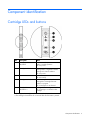
Component identification
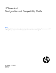
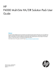
Cartridge LEDs and buttons
Item
Description
Status
1
Cartridge power
LED/button
Green = Normal operation
Amber = Standby operation
Off = No power
2
Cartridge health LED
Green = Normal operation
Flashing amber = Degraded condition
Flashing red = Critical condition
Off = No power
3
Drive LED*
Green = Activity
Off = No activity
4
Cartridge UID LED/button
Blue = Cartridge ID is selected.
Flashing blue = Cartridge firmware
update is in progress.
Off = Cartridge ID is not selected.
5
Cartridge link
LED/button**
Flashing white = Cartridges are linked.
Off = Cartridge is not linked to other
cartridges.
*Depending on the cartridge installed, there may be 0, 1, or 2 drive LEDs.
**The cartridge link LED flashes for 10 seconds after the link button is pressed.
Component identification 5
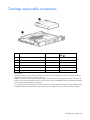
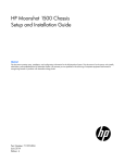
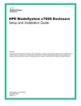
Cartridge components
The HP ProLiant m300 server cartridge supports one drive option.
Component identification 6
Operations
Power down the node
If you are powering down one node but leaving other nodes in a powered up state on the cartridge, the
cartridge power LED will remain illuminated, indicating at least one node is powered up.
To power down the cartridge:
1.
Log in to the iLO CM firmware (on page 12).
2.
Power down the cartridge by issuing the appropriate command.
For a cartridge running a functioning OS:
set node power off shutdown C<x>N<y>
For a nonresponsive system, or when an OS has not been installed:
set node power off force C<x>N<y>
For all cartridges:
set node power off force all
3.
Verify that the power is off by reviewing the status of the cartridge power LED. For more information, see
"Cartridge LEDs and buttons (on page 5)."
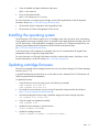
Extend the chassis from the rack
1.
Pull down the quick release levers on each side of the chassis.
2.
Extend the chassis from the rack until it locks once.
3.
Press the push tab on the rail, and then fully extend the chassis.
WARNING: To reduce the risk of personal injury or equipment damage, be sure that the rack is
adequately stabilized before extending a component from the rack.
Operations
7
4.
After performing the installation or maintenance procedure, slide the chassis back into the rack, and
then press the chassis firmly into the rack to secure it in place.
WARNING: To reduce the risk of personal injury, be careful when pressing the server rail-release
latches and sliding the server into the rack. The sliding rails could pinch your fingers.
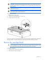
Remove the access panel
Operations
8
IMPORTANT: After performing a procedure inside the chassis, always install the access panel on
the chassis when complete. Do not operate the chassis for long periods of time with the access
panel removed.
IMPORTANT: To maintain appropriate cooling, fans will operate at a high speed when the
access panel is removed.
IMPORTANT: When the access panel is removed, the cartridge might be placed into a low
power operating state to reduce thermal stress.
To remove the access panel:
1.
Release the access panel latch.
2.
Slide the access panel back about 1.5 cm (0.5 in).
3.
Lift and remove the access panel.
Turn the access panel over to locate the HP Moonshot 1500 Chassis label. This label provides information on
LED status indicators, component identification, and cartridge and switch installation procedures.
Remove the cartridge blank
CAUTION: For proper cooling, be sure that a cartridge or a cartridge blank is always installed
in each cartridge slot in the chassis. When replacing a cartridge, leave the cartridge slot empty
for no more than 30 seconds. Failure to do so can disrupt airflow in the chassis.
To remove the component:
1.
Extend the chassis from the rack (on page 7).
2.
Remove the access panel (on page 8).
Operations
9
3.
Remove the component as indicated.
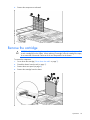
Remove the cartridge
CAUTION: For proper cooling, be sure that a cartridge or a cartridge blank is always installed
in each cartridge slot in the chassis. When replacing a cartridge, leave the cartridge slot empty
for no more than 30 seconds. Failure to do so can disrupt airflow in the chassis.
To remove the component:
1.
Power down the cartridge ("Power down the node" on page 7).
2.
Extend the chassis from the rack (on page 7).
3.
Remove the access panel (on page 8).
4.
Remove the cartridge from the chassis.
Operations
10
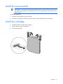
Install the access panel
IMPORTANT: After performing a procedure inside the chassis, always install the access panel on
the chassis when complete. Do not operate the chassis for long periods of time with the access
panel removed.
To install the component:
1.
Place the access panel on top of the chassis.
2.
Slide the access panel toward the front of the chassis. The access panel locks into position.
Install the cartridge
1.
Extend the chassis from the rack (on page 7).
2.
Remove the access panel (on page 8).
3.
Prepare the cartridge.
Operations
11
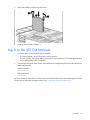
4.
Align and install the cartridge into the chassis.
5.
Install the access panel (on page 11).
Log in to the iLO CM firmware
1.
2.
Connect to the iLO CM firmware locally or remotely:
o
To connect remotely, use an SSH session over the network.
o
To connect locally, use a serial cable to connect a PC or terminal to the iLO CM management serial
port on the Moonshot 1500 CM module.
If no changes were made, enter the user name and password assigned for the chassis or the default user
name and password:
Default username:
Administrator
Default password:
password
For more information about the iLO CM firmware, see the HP Moonshot iLO Chassis Management CLI User
Guide in the HP Moonshot Information Library (http://www.hp.com/go/moonshot/docs).
Operations
12
Setup
Overview
Installation of a cartridge requires the following steps:
1.
Install and configure an HP Moonshot 1500 Chassis ("Installing and configuring an HP Moonshot 1500
Chassis" on page 13).
2.
Install and configure the switch and uplink modules ("Installing and configuring the switch and uplink
modules" on page 13).
3.
Install the drive ("Installing the drive" on page 13).
4.
Install the cartridge (on page 11).
5.
Power up the chassis ("Powering up the chassis" on page 14).
6.
Power on the cartridge, if necessary ("Powering up the node" on page 14).
7.
Configure the cartridge ("Powering up the node" on page 14).
8.
Install the operating system ("Installing the operating system" on page 15).
Installing and configuring an HP Moonshot 1500
Chassis
Before performing any cartridge-specific procedures, install an HP ProLiant Moonshot 1500 Chassis. For
more information on installing a chassis, see HP Moonshot 1500 Chassis Setup and Installation Guide in the
HP Moonshot Information Library (http://www.hp.com/go/moonshot/docs).
Installing and configuring the switch and uplink
modules
For specific steps to install the switch modules and uplink modules, see the switch documentation in the HP
Moonshot Information Library (http://www.hp.com/go/moonshot/docs).
Installing the drive
1.
Extend the chassis from the rack (on page 7).
2.
Remove the access panel (on page 8).
3.
Remove the cartridge (on page 10).
4.
Remove the drive, if necessary ("Drive" on page 24).
Setup
13
5.
Install the drive.
6.
Install the cartridge (on page 11).
7.
Install the access panel (on page 11).
Installing the cartridge
1.
2.
Do one of the following:
o
Remove the cartridge blank (on page 9).
o
Remove a cartridge ("Remove the cartridge" on page 10).
Install the cartridge (on page 11).
Powering up the chassis
If the chassis was powered off while installing the cartridge, then power up the chassis. The cartridges are
hot-pluggable and do not require that you power down the chassis for installation.
1.
Connect the power cables to the power supplies.
2.
Connect the power cables to the power source (UPS or wall outlet) or to an installed PDU.
3.
Wait while the chassis powers on. Verify the status of the chassis power LED located on the front panel
display on the chassis. For more information on the chassis power LED status, see the HP Moonshot
1500 Chassis Setup and Installation Guide in the HP Moonshot Information Library
(http://www.hp.com/go/moonshot/docs).
Powering up the node
Upon installation into the chassis, auxiliary power is provided to the cartridge. Depending on chassis
autopower state, nodes may power up automatically upon cartridge installation.
To power up the node:
1.
Log in to the iLO CM firmware (on page 12).
Setup
14
2.
Show the installed cartridges to determine node status:
hpiLO -> show node list
3.
Power up the preferred node:
hpiLO -> set node power on C<x>N<y>
For more information on configuring the cartridge, see the following documents on the HP Moonshot
Information Library (http://www.hp.com/go/moonshot/docs):
•
HP Moonshot System Configuration and Compatibility Guide
•
HP Moonshot iLO Chassis Management CLI User Guide
Installing the operating system
The HP Moonshot 1500 Chassis supports up to 45 cartridges, each with a processor, drive, and memory,
and is capable of running an operating system. It is possible to individually load each cartridge with an OS
via PXE, particularly if a full complement of cartridges is not present. For OS deployment procedures, see
operating system deployment documentation in the HP Moonshot Information Library
(http://www.hp.com/go/moonshot/docs).
To quickly provision a full complement of cartridges with Linux, HP recommends the HP Insight Cluster
Management Utility for large-scale image deployment.
For more information on HP Insight CMU features and links to technical documents, QuickSpecs, and a
product demonstration, see the HP website (http://www.hp.com/go/cmu).
Updating cartridge firmware
The minimum supported chassis manager firmware version for use with this cartridge is iLO Chassis Manager
Firmware version 1.10.
A system ROM flash does not take effect on a node until the node is rebooted. The iLO CM firmware will
reflect the system ROM flash immediately.
To update the firmware:
1.
Verify the firmware version by entering one of the following commands:
SHOW FIRMWARE REVISIONS ALL
SHOW FIRMWARE REVISIONS LIST
2.
Download the correct firmware version from the HP Moonshot Component Pack download site
(http://www.hp.com/go/moonshot/download).
3.
After downloading the firmware image, upload the image to the chassis manager repository:
ADD FIRMWARE FILE <SOURCE URL>
4.
Verify the image was uploaded successfully:
SHOW FIRMWARE FILES
5.
Update the chassis manager or system firmware:
UPDATE FIRMWARE <FILENAME>
6.
Update the cartridge firmware:
UPDATE FIRMWARE <FILENAME> [C<CARTRIDGE NUMBER>]
Setup
15
For more information on updating the firmware, see the HP Moonshot iLO Chassis Management CLI User
Guide in the HP Moonshot Information Library (http://www.hp.com/go/moonshot/docs).
Registering the product
To experience quicker service and more efficient support, register the product at the HP Product Registration
website (http://register.hp.com).
Setup
16
Hardware options installation
Drive option
For more information about the drives supported on the cartridge, see the HP product Quickspecs on the HP
website (http://www.hp.com/go/productbulletin).
To install the component:
1.
Extend the chassis from the rack (on page 7).
2.
Remove the access panel (on page 8).
3.
Determine the status of the drive from the drive LED definitions ("Cartridge LEDs and buttons" on page
5).
4.
Power down the node (on page 7).
5.
Remove the cartridge (on page 10).
6.
Remove the drive, if necessary ("Drive" on page 24).
7.
Install the drive on the cartridge.
8.
Install the cartridge (on page 11).
9.
Install the access panel (on page 11).
Hardware options installation
17
Software and configuration utilities
HP product QuickSpecs
For more information about product features, specifications, options, configurations, and compatibility, see
the product QuickSpecs on the HP Product Bulletin website (http://www.hp.com/go/productbulletin).
HP Moonshot iLO Chassis Management Firmware
HP Moonshot iLO Chassis Management Firmware is the gateway for aggregated chassis management on
the HP Moonshot System. As a single point of access to the chassis, iLO CM firmware enables you to
configure, update, and operate the HP Moonshot System through CLI, IPMI, and remote serial console
access.
For more information, see the HP Moonshot iLO Chassis Management CLI User Guide in the HP Moonshot
Information Library (http://www.hp.com/go/moonshot/docs).
HP Moonshot iLO CM Integrated Management Log
The iLO CM IML records hundreds of events and stores them in an easy-to-view form. The iLO CM IML
timestamps each event with 1-minute granularity. To view recorded events in the iLO CM IML, use the show
log iml all command in iLO CM firmware. To save the log, cut and paste the content from the session
window or set session logging in the SSH client.
For more information, see the HP Moonshot iLO Chassis Management CLI User Guide in the HP Moonshot
Information Library (http://www.hp.com/go/moonshot/docs).
HP Moonshot iLO CM Event Log
The iLO CM Event Log is an operating system-independent log that maintains a record of events by date and
time. Logged events include major events, such as a power outage or a reset, and iLO CM firmware events.
To view recorded events in the iLO CM Event Log, use the show log ilo all command in iLO CM
firmware. To save the log, cut and paste the content from the session window or set session logging in the
SSH client.
For more information, see the HP Moonshot iLO Chassis Management CLI User Guide in the HP Moonshot
Information Library (http://www.hp.com/go/moonshot/docs).
HP Insight Cluster Management Utility
HP Insight CMU is an efficient and robust hyperscale cluster lifecycle management framework and suite of
tools for large Linux clusters. A simple graphical interface enables an at-a-glance view of the entire cluster
across multiple metrics, provides frictionless scalable remote management and analysis, and allows rapid
software provisioning to all system nodes. HP Insight CMU makes cluster management more user friendly,
efficient, and error-free than if it were being managed by scripts, or on a node-by-node basis. HP Insight
Software and configuration utilities
18
CMU is highly flexible and customizable, offers both GUI and CLI interfaces, and is used to deploy a range
of software environments, from simple compute farms to highly customized, application-specific
configurations.
For more information on HP Insight CMU features and links to technical documentation, Quickspecs, and a
product demo, see the HP website (http://www.hp.com/go/cmu).
To download the product, go to the HP Software Depot
(https://h20392.www2.hp.com/portal/swdepot/index.do). Click HP Insight Management, then click
Insight Cluster Management.
HP Moonshot Component Pack
HP Moonshot Component Pack is a comprehensive firmware solution tested on the HP Moonshot System and
delivered as a compressed file. The compressed file includes all the component files needed to update a
Moonshot System. Firmware updates contained in the Moonshot Component Pack are deployed via the iLO
Chassis Manager CLI interface. Flashing the firmware components consists of delivering and executing
updated files in the HP Moonshot iLO Chassis Management Firmware, which distributes the flash file.
Download the latest pack from the HP website (http://www.hp.com/go/moonshot/download).
Software and configuration utilities
19
Troubleshooting
Troubleshooting resources
The HP Moonshot System Troubleshooting Guide provides procedures for resolving common problems and
comprehensive courses of action for fault isolation and identification, issue resolution, and software
maintenance on the HP Moonshot System. The document is available in the HP Moonshot Information Library
(http://www.hp.com/go/moonshot/docs).
Troubleshooting
20
Illustrated parts catalog
Customer self repair
HP products are designed with many Customer Self Repair (CSR) parts to minimize repair time and allow for
greater flexibility in performing defective parts replacement. If during the diagnosis period HP (or HP service
providers or service partners) identifies that the repair can be accomplished by the use of a CSR part, HP will
ship that part directly to you for replacement. There are two categories of CSR parts:
•
Mandatory—Parts for which customer self repair is mandatory. If you request HP to replace these parts,
you will be charged for the travel and labor costs of this service.
•
Optional—Parts for which customer self repair is optional. These parts are also designed for customer
self repair. If, however, you require that HP replace them for you, there may or may not be additional
charges, depending on the type of warranty service designated for your product.
NOTE: Some HP parts are not designed for customer self repair. In order to satisfy the customer warranty,
HP requires that an authorized service provider replace the part. These parts are identified as "No" in the
Illustrated Parts Catalog.
Based on availability and where geography permits, CSR parts will be shipped for next business day
delivery. Same day or four-hour delivery may be offered at an additional charge where geography permits.
If assistance is required, you can call the HP Technical Support Center and a technician will help you over the
telephone. HP specifies in the materials shipped with a replacement CSR part whether a defective part must
be returned to HP. In cases where it is required to return the defective part to HP, you must ship the defective
part back to HP within a defined period of time, normally five (5) business days. The defective part must be
returned with the associated documentation in the provided shipping material. Failure to return the defective
part may result in HP billing you for the replacement. With a customer self repair, HP will pay all shipping
and part return costs and determine the courier/carrier to be used.
For more information about HP's Customer Self Repair program, contact your local service provider. For the
North American program, refer to the HP website (http://www.hp.com/go/selfrepair).
Parts only warranty service
Your HP Limited Warranty may include a parts only warranty service. Under the terms of parts only warranty
service, HP will provide replacement parts free of charge.
For parts only warranty service, CSR part replacement is mandatory. If you request HP to replace these parts,
you will be charged for the travel and labor costs of this service.
Illustrated parts catalog
21
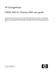
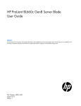
Cartridge replaceable components
Item
Description
Spare part number
Customer self repair (on
page 21)
1
HP ProLiant m300 Server Cartridge
734796-001
Mandatory1
2
Drives
—
—
a) 500-GB, SATA, SFF, 7,200-rpm, 6G
632142-001
Mandatory1
b) 1-TB, SATA, SFF, 7,200-rpm, 6G*
632143-001
Mandatory1
c) 240-GB, SSD, SFF, 6G*
718295-001
Mandatory1
Cartridge blank*
712680-001
Mandatory1
3
* Not shown
1
Mandatory—Parts for which customer self repair is mandatory. If you request HP to replace these parts, you will be
charged for the travel and labor costs of this service.
2
Optional—Parts for which customer self repair is optional. These parts are also designed for customer self repair. If,
however, you require that HP replace them for you, there may or may not be additional charges, depending on the type
of warranty service designated for your product.
3
No—Some HP parts are not designed for customer self repair. In order to satisfy the customer warranty, HP requires that
an authorized service provider replace the part. These parts are identified as "No" in the Illustrated Parts Catalog.
Illustrated parts catalog
22
Removal and replacement procedures
Preparation procedures
To access some components and perform certain service procedures, you must perform one or more of the
following procedures:
•
Remove the access panel (on page 8).
•
Install the access panel (on page 11).
•
Remove the cartridge (on page 10).
•
Install the cartridge (on page 11).
Safety considerations
Before performing service procedures, review all the safety information.
Preventing electrostatic discharge
To prevent damaging the system, be aware of the precautions you need to follow when setting up the system
or handling parts. A discharge of static electricity from a finger or other conductor may damage system
boards or other static-sensitive devices. This type of damage may reduce the life expectancy of the device.
To prevent electrostatic damage:
•
Avoid hand contact by transporting and storing products in static-safe containers.
•
Keep electrostatic-sensitive parts in their containers until they arrive at static-free workstations.
•
Place parts on a grounded surface before removing them from their containers.
•
Avoid touching pins, leads, or circuitry.
•
Always be properly grounded when touching a static-sensitive component or assembly.
Symbols on equipment
The following symbols may be placed on equipment to indicate the presence of potentially hazardous
conditions.
This symbol indicates the presence of hazardous energy circuits or electric shock
hazards. Refer all servicing to qualified personnel.
WARNING: To reduce the risk of injury from electric shock hazards, do not open this
enclosure. Refer all maintenance, upgrades, and servicing to qualified personnel.
Removal and replacement procedures
23
This symbol indicates the presence of electric shock hazards. The area contains no user
or field serviceable parts. Do not open for any reason.
WARNING: To reduce the risk of injury from electric shock hazards, do not open this
enclosure.
This symbol on an RJ-45 receptacle indicates a network interface connection.
WARNING: To reduce the risk of electric shock, fire, or damage to the equipment, do
not plug telephone or telecommunications connectors into this receptacle.
This symbol indicates the presence of a hot surface or hot component. If this surface is
contacted, the potential for injury exists.
WARNING: To reduce the risk of injury from a hot component, allow the surface to cool
before touching.
43.09 kg
95.00 lb
This symbol indicates that the component exceeds the recommended weight for one
individual to handle safely.
WARNING: To reduce the risk of personal injury or damage to the equipment, observe
local occupational health and safety requirements and guidelines for manual material
handling.
These symbols, on power supplies or systems, indicate that the equipment is supplied
by multiple sources of power.
WARNING: To reduce the risk of injury from electric shock, remove all power cords to
completely disconnect power from the system.
Warnings and cautions
Before installing a chassis, be sure that you understand the following warnings and cautions.
WARNING: To reduce the risk of electric shock or damage to the equipment:
• Do not disable the power cord grounding plug. The grounding plug is an important safety
feature.
• Connect the power cord into a grounded (earthed) electrical outlet that is easily accessible at
all times.
• Disconnect the power cord from the power supply to disconnect power to the equipment.
• Do not route the power cord where it can be walked on or pinched by items placed against it.
Pay particular attention to the plug, electrical outlet, and the point where the cord extends from
the chassis.
CAUTION: Do not operate the chassis for long periods with the access panel open or removed.
Operating the chassis in this manner results in improper airflow and improper cooling that can
lead to thermal damage.
Drive
To remove the component:
1.
Extend the chassis from the rack (on page 7).
2.
Remove the access panel (on page 8).
Removal and replacement procedures
24
3.
Determine the status of the drive from the drive LED definitions ("Cartridge LEDs and buttons" on page
5).
4.
Power down the node (on page 7).
5.
Remove the cartridge (on page 10).
6.
Back up all data on the drive.
7.
Remove the drive.
To replace the components, reverse the removal procedure.
Cartridge
When a cartridge fails and a replacement cartridge is installed in the chassis, you must update the serial
number and the product ID to preserve the warranty entitlement for that cartridge.
Before you begin the replacement procedure, make note of the cartridge slot number for the cartridge being
replaced.
To remove the component:
1.
Log in to the iLO CM firmware (on page 12). For more information about the iLO CM firmware, see the
HP Moonshot iLO Chassis Management CLI User Guide on the HP website
(http://www.hp.com/go/moonshot/docs).
2.
Capture the serial number using the following command:
SHOW CARTRIDGE SN C<x>
3.
4.
Capture the product ID using the following command:
SHOW CARTRIDGE PID C<x>
If the failed cartridge is powered on, then power down the failed cartridge using the following
command:
SET NODE POWER OFF FORCE C<x>N<y>
For multinode cartridges, use the command:
SET NODE POWER OFF FORCE C<x>N<1-4>
5.
Power down the node (on page 7).
Removal and replacement procedures
25
6.
Extend the chassis from the rack (on page 7).
7.
Remove the access panel (on page 8).
8.
Remove the failed cartridge.
9.
Remove the drive from the failed cartridge, if installed.
Removal and replacement procedures
26
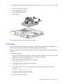
To replace the component:
1.
Install the drive from the failed cartridge on the replacement cartridge.
2.
Prepare the replacement cartridge for installation.
Removal and replacement procedures
27
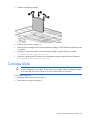
3.
Install the replacement cartridge.
4.
Install the access panel (on page 11).
5.
Allow the chassis manager to discover the replacement cartridge. The link LED flashes when this process
is complete.
6.
Assign the original serial number to the replacement cartridge using the following command:
SET CARTRIDGE SN <original SN> C<x>
7.
Assign the original product ID number to the replacement cartridge using the following command:
SET CARTRIDGE PID <original PID> C<x>
Cartridge blank
CAUTION: For proper cooling, be sure that a cartridge or a cartridge blank is always installed
in each cartridge slot in the chassis. When replacing a cartridge, leave the cartridge slot empty
for no more than 30 seconds. Failure to do so can disrupt airflow in the chassis.
To remove the component:
1.
Extend the chassis from the rack (on page 7).
2.
Remove the access panel (on page 8).
Removal and replacement procedures
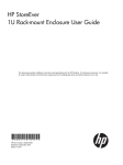
28
3.
Remove the component as indicated.
To replace the component, reverse the removal procedure.
Removal and replacement procedures
29
Regulatory information
Safety and regulatory compliance
For safety, environmental, and regulatory information, see Safety and Compliance Information for Server,
Storage, Power, Networking, and Rack Products, available at the HP website
(http://www.hp.com/support/Safety-Compliance-EnterpriseProducts).
Belarus Kazakhstan Russia marking
Manufacturer
Hewlett-Packard Company, Address: 3000 Hanover Street, Palo Alto, California 94304, U.S.
Local representative information (Russian)
•
HP Russia
•
HP Belarus
•
HP Kazakhstan
Local representative information (Kazakh)
Manufacturing date
The manufacturing date is defined by the serial number (HP serial number format for this product):
CCSYWWZZZZ
Regulatory information 30
Valid date formats include the following:
•
YWW, where Y indicates the year counting from within each new decade, with 2000 as the starting
point. For example, 238: 2 for 2002 and 38 for the week of September 9. In addition, 2010 is
indicated by 0, 2011 by 1, 2012 by 2, 2013 by 3, and so forth.
•
YYWW, where YY indicates the year, using a base year of 2000. For example, 0238: 02 for 2002 and
38 for the week of September 9.
Turkey RoHS material content declaration
Ukraine RoHS material content declaration
Warranty information
HP ProLiant and X86 Servers and Options (http://www.hp.com/support/ProLiantServers-Warranties)
HP Enterprise Servers (http://www.hp.com/support/EnterpriseServers-Warranties)
HP Storage Products (http://www.hp.com/support/Storage-Warranties)
HP Networking Products (http://www.hp.com/support/Networking-Warranties)
Regulatory information 31
Electrostatic discharge
Preventing electrostatic discharge
To prevent damaging the system, be aware of the precautions you need to follow when setting up the system
or handling parts. A discharge of static electricity from a finger or other conductor may damage system
boards or other static-sensitive devices. This type of damage may reduce the life expectancy of the device.
To prevent electrostatic damage:
•
Avoid hand contact by transporting and storing products in static-safe containers.
•
Keep electrostatic-sensitive parts in their containers until they arrive at static-free workstations.
•
Place parts on a grounded surface before removing them from their containers.
•
Avoid touching pins, leads, or circuitry.
•
Always be properly grounded when touching a static-sensitive component or assembly.
Grounding methods to prevent electrostatic discharge
Several methods are used for grounding. Use one or more of the following methods when handling or
installing electrostatic-sensitive parts:
•
Use a wrist strap connected by a ground cord to a grounded workstation or computer chassis. Wrist
straps are flexible straps with a minimum of 1 megohm ±10 percent resistance in the ground cords. To
provide proper ground, wear the strap snug against the skin.
•
Use heel straps, toe straps, or boot straps at standing workstations. Wear the straps on both feet when
standing on conductive floors or dissipating floor mats.
•
Use conductive field service tools.
•
Use a portable field service kit with a folding static-dissipating work mat.
If you do not have any of the suggested equipment for proper grounding, have an authorized reseller install
the part.
For more information on static electricity or assistance with product installation, contact an authorized
reseller.
Electrostatic discharge
32
Specifications
Chassis environmental specifications
Specification
Value
Temperature range*
—
Operating
10°C to 35°C (50°F to 95°F)
Non-operating
-30°C to 60°C (-22°F to
140°F)
Maximum Wet bulb temperature
—
Operating
28ºC (82.4ºF)
Non-operating
38.7ºC (101.7ºF)
Relative humidity (noncondensing)** —
Operating
10% to 90%
Non-operating
5% to 95%
* All temperature ratings shown are for sea level. An altitude derating of 1°C per 304.8 m (1.8°F per 1000 ft) to 3048
m (10,000 ft) is applicable. No direct sunlight allowed. Upper operating limit is 3,048 m (10,000 ft) or 70 kPa/10.1
psia. Upper non-operating limit is 9,144 m (30,000 ft).
** Storage maximum humidity of 95% is based on a maximum temperature of 45°C (113°F). Altitude maximum for
storage corresponds to a pressure minimum of 70 kPa (10.1 psia).
Chassis specifications
Specification
Value
Height
18.96 cm (7.46 in)
Depth
84.91 cm (33.43 in)
Width
44.33 cm (17.45 in)
Weight, fully loaded
81.65 kg (180.00 lb)
Weight, empty
43.09 kg (95.00 lb)
Specifications
33
Support and other resources
Before you contact HP
Be sure to have the following information available before you call HP:
•
Technical support registration number (if applicable)
•
Product name
•
Chassis serial number
•
Product identification number
•
Applicable error messages
•
Operating system type and revision level
To obtain product information, log in to iLO CM firmware and use the Show Chassis Info command. For
more information, see the HP Moonshot iLO Chassis Management CLI User Guide in the HP Moonshot
Information Library (http://www.hp.com/go/moonshot/docs).
HP contact information
For United States and worldwide contact information, see the Contact HP website
(http://www.hp.com/go/assistance).
In the United States:
•
To contact HP by phone, call 1-800-334-5144. For continuous quality improvement, calls may be
recorded or monitored.
•
If you have purchased a Care Pack (service upgrade), see the Support & Drivers website
(http://www8.hp.com/us/en/support-drivers.html). If the problem cannot be resolved at the website,
call 1-800-633-3600. For more information about Care Packs, see the HP website
(http://pro-aq-sama.houston.hp.com/services/cache/10950-0-0-225-121.html).
Support and other resources
34
Acronyms and abbreviations
CM
chassis management
CMU
HP Insight Cluster Management Utility
CSR
Customer Self Repair
DHCP
Dynamic Host Configuration Protocol
ESD
electrostatic discharge
ID
identification
IPMI
Intelligent Platform Management Interface
MAC
Media Access Control
PDU
power distribution unit
PXE
preboot execution environment
SL-APM
HP ProLiant SL Advanced Power Manager
UID
unit identification
Acronyms and abbreviations
35
UPS
uninterruptible power system
VSP
virtual serial port
Acronyms and abbreviations
36
Documentation feedback
HP is committed to providing documentation that meets your needs. To help us improve the documentation,
send any errors, suggestions, or comments to Documentation Feedback (mailto:[email protected]).
Include the document title and part number, version number, or the URL when submitting your feedback.
Index
37
Index
A
access panel 8, 11
authorized reseller 34
B
battery 22
before you contact HP 34
Belarus Kazakhstan Russia marking 30
C
cartridge blank 22, 28
cartridge components 6, 22
cartridge installation 13, 14
cartridge link LED/button 5
cartridge power LED 5
cartridge UID LED/button 5
cartridge, powering down 7
cartridges 7, 28
cautions 24
chassis environmental specifications 33
chassis management 18
chassis specifications 33
chassis, extend from rack 7
chassis, install in rack 13
CMU 18
compliance 30
components 5, 21, 22
configuration of system 18
contact information 34
contacting HP 34
CSR (customer self repair) 21
customer self repair (CSR) 21, 34
drive, removing 24
drive, replacing 17, 24
E
electrostatic discharge 23, 32
environmental requirements 33
EuroAsian Economic Commission 30
event logs 18
extending chassis from rack 7
extending server from rack 7
F
firmware 15
firmware upgrade utility, troubleshooting 20
G
grounding methods 32
H
help resources 34
HP contact information 34
HP Insight Cluster Management Utility 18
HP Moonshot Component Pack 19
HP Moonshot iLO Chassis Management Firmware 18
HP technical support 34
HP website 34
HP, contacting 34
I
installation, chassis 13
installing a cartridge 13, 14
installing a drive 13
D
L
Declaration of Conformity 30, 31
diagnosing problems 20
documentation feedback 37
drive 17, 22, 24
drive bays 6
drive health LED 5
drive, installing 13
LED, cartridge health 5
LED, drive health 5
LED, link 5
LEDs 5
LEDs, troubleshooting 20
link LED 5
Index
38
N
nodes 7, 14
nodes, powering 7, 14
O
operating system installation 15
operations 7
P
part numbers 21, 22, 30
power up procedure 14
preparation procedures 7, 23
Q
telephone numbers 34
troubleshooting 20
troubleshooting resources 20
U
updating firmware 15
uplink module, configuring 13
uplink module, installing 13
utilities 18
W
warnings 24
warranty information 31
website, HP 34
QuickSpecs 18
R
registering the product 16
registering the server 16
regulatory compliance information 30
regulatory compliance notices 30
removal and replacement procedures 23
removing a cartridge 25
replacement procedures 23
required information 34
required tools 23
resources 20, 34
RoHS 31
S
safety considerations 23, 30, 32
safety information 23, 24, 30
server specifications 33
spare part numbers 21, 22
specifications 33
specifications, environmental 33
static electricity 23
support 34
support and other resources 34
switch module, configuring 13
switch module, installing 13
symbols on equipment 23
system board battery 22
system board components 6
T
technical support 34
Index
39