1
LCD Projector
GT2150
User’s Manual
LIMITED WARRANTY
GARANZIA LIMITATA
Except as specified below, the warranty that may be provided by the
dealer covers all defects in material or workmanship in this product.
The following are not covered by the warranty:
A parte la specificazione seguente, la graanzia che potrebbe essere
fornita dal rivenditore copre tutti i difetti di materiali o nella lavorazione
in questo prodotto. I seguenti non sono coperti dalla garanzia :
1. Any product on which the serial number has been defaced, modified
or removed.
2. Damage, deterioration or malfunction resulting from;
a. Accident, misuse, abuse, neglect, fire, water, dust, smoke, lightning or
other acts of nature, unauthorized product modification, or failure to follow instructions supplied with the product.
b. Repair or attempted repair by non-authorized persons.
c. Any shipment of product (claim must be presented to the carrier).
d. Removal or installation of the product.
e. Any other causes which do not relate to a product defect.
3. Cartons, carrying cases, batteries, external cabinets, CDROM, or
anyaccessories used in connection with the product.
4. Removal or installation charges.
5. Cost of initial technical adjustments (set-up), including adjustment of
user controls. These costs are the responsibility of the dealer from
whom the product was purchased.
6. Payment of shipping charges.
1. Ogni prodotto che ha il numero seriale difettoso, modificato o rimosso.
2. Danni, deterioramento o malfunzionamento risultanti da;
a. Incidenti, abuso, cattivo uso, negligenza, fuoco, acqua,polvere,fumo,fulmini
o altri atti naturali di tipo naturale, modifiche inautorizzate del prodotto, o
errori nel seguire le istruzioni fornite con il prodotto.
b. Riparazioni o tentativi di riparazioni effettuati da persono non autorizzate.
c. Qualsiasi trasporto del prodotto (i reclami devono essere presentati dal
corriere).
d. Rimozione o installazione del prodotto.
e. ogni altra causa non relativa ad un deficit del prodotto.
3. Cartoni, scatole di trasporto, batterie, armadietti esterni, CDROM, o
qualsiasi altro accessorio annesso al prodotto.
4. Carichi di rimozione o installazione.
5. Costi di aggiustamenti tecnici iniziali (set-up), includendo i comandi
di regolazione. Il rivenditore dal quale avete acquistato il prodotto è
responsabile di ciò.
6. Pagamento delle spese di consegna.
GARANTIE LIMITEE
GARANTÍA LIMITADA
Mis à part les point indiqués ci-dessous, la garantie pouvant être couverte
par le revendeur comporte l'ensemble des défauts se rapportant au
matériel ou aux travaux d'assemblage sur ce produit. Les points suivants
ne sont pas couverts par la garantie:
A excepción de lo que se especifica abajo, la garantía que puede ser
suministrada por el distribuidor cubre todos los defectos en material o
elaboración en este producto. Lo siguiente no es cubierto por la garantía:
1. Les produits dont les numéro de série a été effacé, modifié ou retiré.
2. Dommages, dégâts ou dysfonctionnement suite à;
a. Un accident, mauvaise utilisation, abus, négligences, incendies, dégats dûs
aux eaux, à la poussière, à la fumée, aux éclairs ou autres phénomènes
naturels, à une modification non autorisée du produit, ou à la non-conformité
aux instructions fournies avec le produit.
b. Réparation ou tentative de réparation par des personnes non autorisées.
c. Toute expédition du produit (les plaintes doivent être adressées à la société
de frêt).
d. Démontage ou installation du produit.
e. Toute autre cause ne se rapportant pas à un défaut du produit.
3. Les cartons, boîtes, piles, caissons externes, CDROM, ou tout autre
accessoire utilisé avec ce poduit.
4. Prix de démontage ou d'installation.
5. Coût des réglages techniques de base (mise au point), incluant les
réglages des commandes utilisateurs. Ces coûts sont placés sous la
responsabilité du revendeur auprès duquel le produit a été acheté.
6. Paiement des frais de transport.
1. Cualquier producto en el cual el número serial haya sido desfigurado,
modificado o removido.
2. Daños, deterioro o malfuncionamiento resultado de;
a. Accidente, mal manejo, abuso, negligencia, fuego, agua, polvo, humo,
relámpagos u otros fenómenos naturales, modificaciones del producto sin
autorización, fallas en el seguimiento de las instrucciones suministradas
con el producto.
b. Reparación o intentos de reparación por personas no autorizadas.
c. Cualquier envío del producto (el reclamo debe presentarse al transportador).
d. Remoción o instalación del producto.
e. Cualquier otra causa que no este relacionada con un defecto del producto.
3. Cartones, estuches de transporte, pilas, gabinetes externos, CDROM,
o cualquier accesorio utilizado en conexión con el producto.
4. Costos por instalación o remoción.
5. Costo de los ajustes técnicos iniciales (configuración), incluyendo el
ajuste de los controles de usuario. Estos costos son responsabilidad
del distribuidor donde se adquirió el producto.
6. Pago de los costos de envío.
BEGRÄNSAD GARANTI
BESCHRÄNKTE GARANTIE
Außer in den unten beschriebenen Fällen deckt die vom Händler unter
Umständen gewährte Garantie alle Material- oder Herstellungsfehler
dieses Produktes ab. In den folgenden Fällen wird keine Garantie
gewährt:
1. Wenn die Seriennummer des Produktes unleserlich gemacht,
geändert oder entfernt worden ist.
2. Bei einer Beschädigung, Beeinträchtigung oder Funktionsstörung,
die aus folgenden Fällen resultiert:
a. Unfall, falscher Gebrauch, Missbrauch, Fahrlässigkeit, Feuer, Wasser, Staub,
Rauch, Blitzeinschlag oder andere Naturereignisse, nicht autorisierte
Veränderungen des Produktes oder die Missachtung der dem Produkt
beigefügten Anleitung.
b. Reparatur oder der Versuch einer Reparatur durch nicht autorisierte
Personen.
c. Jeglicher Transport des Produktes (die Haftung liegt in diesem Fall bei der
den Transport durchführenden Person).
d. Entfernung oder Installation des Produktes.
e. Jegliche andere Ursachen, die nicht mit einem Defekt dieses Produktes
zusammenhängen.
3. Verwendung von Kar tons, Transpor tkisten, Batterien,
Außengehäusen, CD-ROMs oder anderem Zubehör zusammen mit
diesem Produkt.
4. Entfernungs- oder Installationsforderungen und –kosten.
5. Kosten der technischen Anfangseinstellungen (Setup), einschließlich
der Einstellungen der Benutzersteuerungen. Diese Kosten sind vom
Händler zu tragen, von dem das Produkt erworben wurde.
6. Bezahlung von Transportkosten.
Garantin som ges av återförsäljaren täcker alla brister i material och
utförande med undantag av vad som anges nedan. Följande täcks inte
av garantin:
1. Produkter vars serienummer har blivit oläsligt, modifierats eller tagits
bort.
2. Skador, försämring eller felfunktion som beror på:
a. Olyckor, fel bruk, missbruk, vanskötsel, brand, vatten, rök, stoft, åska eller
annan orsak som beror på naturen, icke auktoriserad modifikation av
produkten samt underlåtenhet att följa anvisningarna som lämnas med
produkten.
b. Reparationer eller försök på reparation av icke auktoriserade personer.
c. Transportskador (dessa bör riktas till transportföretaget).
d. Avmontering eller installation av produkten.
e. Övriga orsaker som inte har något samband med produktens fel.
3. Förpackningslådor, bärväskor, batterier, externa höljen, CD-ROMskivor samt andra tillbehör som används tillsammans med produkten.
4. Avmonterings- och installationskostnader.
5. Kostnader för tekniska justeringar (inställning), inklusive justering av
användarreglagen. Dessa kostnader är återförsäljarens ansvar där
produkten köpts.
6. Betalning för transportkostnader.
S
U
C
FO
M
O
ZO
FT
LE
P
U
S
N
LE
T
IF
H
S
N
W
O
D
T
H
IG
R
N
U
ENTE R
T
C
LE
E
S
E
C
R
U
O
S
CEL
CAN
P
M
LA
S
TU
TA
S
T
TO S
U
A DJU
A
N
O
Y
B
R
E
W
O
P
D
N
TA
/S
LCD Projector
GT2150
User’s Manual
ME
IMPORTANT INFORMATION
Precautions
RF Interference
WARNING
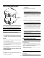
Please read this manual carefully before using your NEC GT2150 Projector and keep the manual handy for future reference.
Your serial number is located on the bottom of your GT2150. Record it
here:
The Federal Communications Commission does not allow any
modifications or changes to the unit EXCEPT those specified by
NEC Technologies in this manual. Failure to comply with this government regulation could void your right to operate this equipment.
This equipment has been tested and found to comply with the
limits for a Class B digital device, pursuant to Part 15 of the FCC
Rules. These limits are designed to provide reasonable protection
against harmful interference in a residential installation. This equipment generates, uses, and can radiate radio frequency energy
and, if not installed and used in accordance with the instructions,
may cause harmful interference to radio communications. However, there is no guarantee that interference will not occur in a
particular installation. If this equipment does cause harmful interference to radio or television reception, which can be determined
by turning the equipment off and on, the user is encouraged to try
to correct the interference by one or more of the following measures:
• Reorient or relocate the receiving antenna.
• Increase the separation between the equipment and receiver.
• Connect the equipment into an outlet on a circuit different from that to
which the receiver is connected.
• Consult the dealer or an experienced radio / TV technician for help.
CAUTION
To turn off main power, be sure to remove the plug from
power outlet.
The power outlet socket should be installed as near to
the equipment as possible, and should be easily accessible.
CAUTION
TO PREVENT SHOCK, DO NOT OPEN THE CABINET.
NO USER-SERVICEABLE PARTS INSIDE.
REFER SERVICING TO QUALIFIED NEC SERVICE
PERSONNEL.
This symbol warns the user that uninsulated voltage
within the unit may be sufficient to cause electrical shock.
Therefore, it is dangerous to make any kind of contact
with any part inside of the unit.
In UK, a BS approved power cable with moulded plug has a Black (five
Amps) fuse installed for use with this equipment. If a power cable is not
supplied with this equipment please contact your supplier.
This symbol alerts the user that important information
concerning the operation and maintenance of this unit
has been provided. The information should be read carefully to avoid problems.
WARNING
TO PREVENT FIRE OR SHOCK, DO NOT EXPOSE THIS UNIT TO
RAIN OR MOISTURE.
DO NOT USE THIS UNIT’S GROUNDED PLUG WITH AN EXTENSION CORD OR IN AN OUTLET UNLESS ALL THREE PRONGS CAN
BE FULLY INSERTED.
DO NOT OPEN THE CABINET. THERE ARE HIGH-VOLTAGE COMPONENTS INSIDE. ALL SERVICING MUST BE DONE BY QUALIFIED NEC SERVICE PERSONNEL.
DOC Compliance Notice
This Class B digital apparatus meets all requirements of the Canadian
Interference-Causing Equipment Regulations.
3. GSGV Acoustic Noise Information Ordinance:
The sound pressure level is less than 70 dB (A) according to ISO 3744
or ISO 7779.
• IBM is a registered trademark of International Business Machines
Corporation.
• Macintosh and PowerBook are registered trademarks of Apple Computer, Inc.
• Other product and company names mentioned in this user's manual
may be the trademarks of their respective holders.
E – ii
INFORMATIONS IMPORTANTES
Précautions
Veuillez lire ce manuel avec attention avant d’utiliser votre projecteur
NEC GT2150 et gardez ce manuel à portée de main afin de pouvoir y
recourir facilement.
Votre numéro de série est situé sur le fond de votre GT2150. Reportezle ici:
ATTENTION
Pour couper complètement l’alimentation, retirez la prise
du secteur.
La prise du secteur doit être accessible et installée le
plus près possible de l’appareil.
ATTENTION
POUR ÉVITER TOUT CHOC ÉLECTRIQUE, N’OUVREZ PAS LE
BOÎTIER. LES PIÈCES INTERNES NE SONT PAS RÉPARABLES
PAR L’UTILISATEUR. POUR TOUTE RÉPARATION, ADRESSEZVOUS À UN RÉPARATEUR AGRÉE NEC.
Ce symbole avertit l’utilisateur que le contact avec
certaines parties non isolées à l’intérieur de l’appareil
risque de causer une électrocution. Il est donc dangereux
de toucher quoi que ce soit à l’intérieur de l’appareil.
Ce symbole avertit l’utilisateur que d’importantes informations sont fournies sur le fonctionnement ou l’entretien
de cet appareil. Ces informations doivent être lues
attentivement pour éviter tout problème.
AVERTISSEMENT
AFIN DE PREVENIR TOUT RISQUE D’INCENDIE OU DE CHOC
ÉLECTRIQUE, N’EXPOSEZ PAS CET APPAREIL À LA PLUIE OU À
L’HUMIDITÉ. N’UTILISEZ PAS LA PRISE AVEC TERRE DE
L’APPAREIL AVEC UNE RALLONGE OU UNE AUTRE PRISE, A
MOINS QUE LES TROIS BROCHES PUISSENT ÊTRE
COMPLETEMENT INSÉRÉES. N’OUVREZ PAS LE BOÎTIER. A
L’INTÉRIEUR SE TROUVENT DES COMPOSANTS À HAUTE TENSION. TOUTE RÉPARATION DOIT ÊTRE FAITE PAR DU PERSONNEL AGRÉE NEC.
DOC avis de conformation
Cet appareil numérique de la classe B respecte toutes les exigences
du Règlement sur le Matériel Brouilleur du Canada.
3. Réglement sur les informations concernant les nuisances acoustiques GSGV:
Le niveau de pression sonore est inférieur à 70 dB (A) conformément
à la norme ISO 3744 ou ISO 7779.
• IBM est une marque déposées de International Business Machines
Corporation.
• Macintosh et PowerBook sont des marques déposées de Apple Computer, Inc.
• Tous les autres marques et les noms de produits sont des marques
de fabrique ou des marques déposées de leurs compagnies
respectives.
E – iii
CAUTION
Important Safeguards
Do not unplug the power cable from the wall outlet under any one
of the following circumstances. Doing so can cause damage to
the projector:
• While the message "Please wait a moment." appears. This message
will be displayed after the projector is turned off.
• Immediately after the power cable is plugged into the wall outlet (the
POWER indicator has not changed to a steady orange glow).
• Immediately after the cooling fan stops working (The cooling fan continues to work for three minutes after the projector is turned off with
the POWER button).
• While the POWER and the STATUS indicators are alternately flashing.
These safety instructions are to ensure the long life of your projector
and to prevent fire and shock. Please read them carefully and heed all
warnings.
Installation
1. For best results, use your projector in a darkened room.
2. Place the projector on a flat, level surface in a dry area away from
dust and moisture.
3. Do not place your projector in direct sunlight, near heaters or heat
radiating appliances.
4. Exposure to direct sunlight, smoke or steam can harm internal components.
5. Handle your projector carefully. Dropping or jarring can damage internal components.
6. Do not place heavy objects on top of the projector.
7. If you wish to have the projector installed on the ceiling:
a. Do not attempt to install the projector yourself.
b. The projector must be installed by qualified technicians in order to ensure
proper operation and reduce the risk of bodily injury.
c. In addition, the ceiling must be strong enough to support the projector
and the installation must be in accordance with any local building codes.
d. Please consult your dealer for more information.
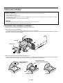
To Dealer or Installer:
To prevent the projector from falling, install it in a place and fasten it in
a way with sufficient strength to support the combined weight (17.0 kg/
37.5 lbs) of the projector (12.8 kg/28.3 lbs), the lens (2.0 kg/4.4 lbs)
and the ceiling mount(2.1 kg/4.7 lbs) for an extended period of time as
well as to withstand earthquakes.
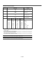
Power Supply
1. The projector is designed to operate on a power supply of 100-120
or 200-240 V 50/60 Hz AC. Ensure that your power supply fits this
requirement before attempting to use your projector.
2. Handle the power cable carefully and avoid excessive bending. A
damaged cord can cause electric shock or fire.
3. If the projector is not to be used for an extended period of time,
disconnect the plug from the power outlet.
Cleaning
1. Unplug the projector before cleaning.
2. Clean the cabinet periodically with a damp cloth. If heavily soiled,
use a mild detergent. Never use strong detergents or solvents such
as alcohol or thinner.
3. Use a blower or lens paper to clean the lens, and be careful not to
scratch or mar the lens.
CAUTION
• Do not put the projector on its side when the lamp is turned on.
Doing so may cause damage to the projector.
• Before shipping this projector, remove the lens and attach the lens
hood cap.
The Lens Shift mechanism may encounter damage caused by improper
handling during transportation.
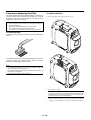
Lamp Replacement
• To replace the lamp, follow all instructions provided on page E-52.
• Be sure to replace the lamp when the message "The Lamp has
reached the end of its usable life. Please replace the lamp."
appears. If you continue to use the lamp after the lamp has reached
the end of its usable life, the lamp bulb may shatter, and pieces of
glass may be scattered in the lamp case. Do not touch them as the
pieces of glass may cause injury. If this happens, contact your NEC
dealer for lamp replacement.
• Allow a minimum of three minutes to elapse after turning off the
projector. Then disconnect the power cable and allow 60 minutes to
cool the projector before replacing the lamp.
Fire and Shock Precautions
1. Ensure that there is sufficient ventilation and that vents are unobstructed to prevent the build-up of heat inside your projector. Allow
at least 3 inches (10 cm) of space between your projector and a
wall.
2. Prevent foreign objects such as paper clips and bits of paper from
falling into your projector. Do not attempt to retrieve any objects that
might fall into your projector. Do not insert any metal objects such as
a wire or screwdriver into your projector. If something should fall into
your projector, disconnect it immediately and have the object removed by a qualified NEC service personnel.
3. Do not place any liquids on top of your projector.
4. When using a LAN cable:
For safety, do not connect to the connector for peripheral device
wiring that might have excessive Voltage.
CAUTION
• Do not look into the lens while the projector is on. Serious damage to
your eyes could result.
• Keep any items such as magnifying glass out of the light path of the
projector. The light being projected from the lens is extensive, therefore any kind of abnormal objects that can redirect light coming out of
the lens, can cause unpredictable outcome such as fire or injury to the
eyes.
• Do not cover the lens with the supplied lens hood cap or equivalent
while the projector is on. Doing so can lead to melting of the cap and
possibly burning your hands due to the heat emitted from the light
output.
E – iv
Mesures de sécurité importantes
Remplacement de la lampe
Ces instructions de sécurité garantissent la longévité de votre projecteur
et préviennent les risques d’incendie et de décharge électrique. Lisezles et respectez les conseils.
• Effectuez le remplacement de la lampe en fonction des instructions
de la page E-54.
• Assurez-vous de remplacer la lampe lorsque le message “La lampe
a atteint sa durée de vie maximum, prière de la remplacer.”
apparaît. Si vous continuer à l ’utiliser au-delà de sa durée de vie,
celle-ci risque d’exploser et de répandre des fragments de verre à
l’intérieur du boîtier.
Ne les touchez pas car elles peuvent vous blesser. Dans ce cas,
contactez votre revendeur NEC afin de procéder au remplacement
de la lampe.
• Attendez au minimum trois minutes aprés avoir éteint la lampe avant
de la rallumer.
Une haute tension est immédiatement appliquée à la lampe quand
celle-ci est mise sous tension.
Par conséquent, éteindre, puis tout de suite rallumer peut réduire la
durée de vie de votre lampe et endommager votre projecteur.
Installation
1. Pour de meilleurs résultats‚ utilisez votre projecteur dans une pièce sombre.
2. Placez le projecteur sur une surface plane et à niveau, dans un
endroit sec à l’abri de la poussière et de l’humidité.
3. Ne placez pas votre projecteur en plein soleil‚ à côté d’appareils de
chauffage ou d’appareils dégageant de la chaleur.
4. L’exposition en plein soleil‚ la fumée ou la vapeur peuvent
endommager des composants internes.
5. Manipulez votre projecteur avec précaution. Une chute ou un choc
peuvent endommager des composants internes.
6. Ne placez pas d’objets lourds sur le projecteur.
7. Si vous voulez installer le projecteur au plafond:
a. N’essayez pas d’installer le projecteur vous-même.
b. Le projecteur doit être installé par un technicien qualifié pour garantir une
installation réussie et réduire le risque d’éventuelles blessures corporelles.
c. De plus le plafond doit être suffisamment solide pour supporter le
projecteur et l’installation doit être conforme aux réglementations locales
de construction.
d. Veuillez consulter votre revendeur pour de plus amples informations.
Alimentation
1. Ce projecteur est conçu pour fonctionner avec une alimentation
électrique de 100-120 ou 200-240 V 50/60 Hz. Assurez-vous que
votre alimentation correspond à ces critères avant d’essayer d’utiliser
votre projecteur.
2. Manipulez le câble d’alimentation avec précaution et évitez de
l’entortiller. Tout câble endommagé peut provoquer une décharge
électrique ou un incendie.
3. Si le projecteur ne doit pas être utilisé pendant longtemps,
débranchez la prise de la source d’alimentation.
Précautions contre les risques d’incendie et de
décharge électrique
1. Assurez-vous que la ventilation est suffisante et que les trous
d’aération ne sont pas obstrués afin d’éviter tout échauffement à
l’intérieur de votre projecteur. Laissez au-moins 3 pouces (10 cm)
d’espace entre le projecteur et le mur.
2. Evitez de faire tomber dans le projecteur des objets étrangers comme
des trombones ou des morceaux de papier. N’essayez pas de
récupérer tout objet tombé à l’intérieur de votre projecteur. N’insérez
pas d’objets métalliques comme du fil de fer ou un tournevis dans
votre projecteur. Si quelque chose est tombée à l’intérieur de votre
projecteur, débranchez-le immédiatement et faites retirer l’objet par
une personne qualifiée de la maintenance NEC.
3. Ne placez aucun liquide sur votre projecteur.
4. Connexion d'un câble LAN une carte LAN:
Pour des raisons de surit, ne pas connecter un reau disposant d'une
tension excessive.
Avertissements
Nettoyage
1. Débranchez le projecteur avant de procéder au nettoyage.
2. Nettoyez régulièrement le coffret avec un chiffon humide. Si celui-ci
est très sale, utilisez un détergent doux. N’utilisez jamais de
détergents puissants, de l’alcool ou d’autres solvants.
3. Utilisez un ventilateur ou un papier à objectif pour nettoyer l’objectif
et faîtes attention de ne pas rayer ou d’abîmer l’objectif.
Information importante
Ne pas débrancher le câble d’alimentation de la prise du secteur dans
les circonstances suivantes car cela risque d’endommager le projecteur:
* Lorsque le message "Veuillez patientez un instant" apparaît. Ce message sera affiché après que le projecteur soit éteint.
* Immédiatement après que le cordon d’alimentation électrique ait été
branché sur la prise du mur (l’indicateur POWER n’est pas encore
devenu orange).
* Immédiatement après que le ventilateur de refroidissement de soit arrêté
de fonctionner (le ventilateur de refroidissement continue à fonctionner
pendant trois minutes après l’extinction du projecteur grâce à
l’interrupteur POWER OFF).
* Lorsque les indicateurs POWER (alimentation électrique) et STATUS
(état) clignotent alternativement.
• Ne regardez pas à l’intérieur de l’objectif lorsque le projecteur est
en marche. Vous risquez de vous blesser gravement aux yeux.
• Maintenez tout ce qui s’apparente à une loupe en dehors du faisceau
lumineux du projecteur. La lumière projetée par l’objectif est très
puissante, de sorte que tout objet en opposition pourrait dévier le
faisceau provenant de l’objectif, ce qui pourrait avoir des
conséquences imprévues telles qu’un incendie ou une lésion
occulaire.
• Ne bouchez pas l’objectif avec son couvercle fourni lorsque le
projecteur est allumé. Faire cela pourrait faire fondre le couvercle et
peut-être brûler vos mains à cause de la châleur émise par le faisceau
lumineux.
ATTETION
• Ne pas placer le projecteur sur le côté lorsque la lampe est allumée,
sinon le projecteur risque d’être endommagé.
• Avant d’expedier ce projecteur, veuillez démonter l’objectif et fixer le
bouchon d’objectif.
Le mécanisme de déplacement de l’objectif pourrait être endommagé
durant le transport à la suite d’une manipulation maladroite.
E–v
LIMITED WARRANTY (USA and Canada only)
NEC SOLUTIONS’ PROJECTOR PRODUCTS
HOW YOU CAN GET WARRANTY SERVICE
NEC Solutions (America), Inc. (hereafter NEC Solutions) warrants
this product to be free from defects in material and workmanship
under the following terms.
1. To obtain service on your product, consult the dealer from whom
you purchased the product.
2. Whenever warranty service is required, the original dated invoice
(or a copy) must be presented as proof of warranty coverage. In
order to obtain warranty service, you may be required to describe
and demonstrate the problem to your dealer or to NEC Solutions.
3. All products returned to NEC Solutions for service MUST have
prior approval. To receive approval or for the name of the
nearest NEC Solutions authorized service center, call NEC
Solutions at 800-836-0655.
4. It shall be your obligation and expense to ship the product,
freight prepaid, or to deliver it to a NEC Solutions authorized
service center, in either the original package or a similar package affording an equal degree of protection.
5. In the event a product is returned to NEC Solutions for warranty
service, and it is determined that there is no product defect or that
the product condition is not covered by this limited warranty, a
diagnostic service fee may be charged to the customer.
HOW LONG IS THE WARRANTY
NEC Solutions’ GT2150 projectors are covered by a two (2)
year limited parts and labor warranty from the date of the first
customer purchase. The lamp when used under normal operating conditions is warranted for 1000 hours or six months,
whichever comes first.
WHO IS PROTECTED
This warranty may be enforced only by the first purchaser, and is
not transferable.
WHAT IS COVERED AND WHAT IS NOT COVERED
Except as specified below, this warranty covers all defects in
material or workmanship in this product.
NEC SOLUTIONS’ LIABILITY FOR ANY DEFECTIVE PRODUCT IS
LIMITED TO THE REPAIR OR REPLACEMENT OF THE PRODUCT
AT NEC SOLUTIONS’ OPTION. REPLACEMENT PRODUCTS MAY
BE NEW OR ‘LIKE NEW’. The following are not covered by the
limited warranty and NEC Solutions shall not be liable for:
1. Any product which is not distributed in the U.S.A. or Canada
by NEC Solutions or which is not purchased, installed, and
operated in the U.S.A or Canada.
2. Any product on which the serial number has been defaced,
modified or removed.
3. Normal decrease in lamp light output over time.
4. Damage, deterioration or malfunction resulting from:
a. Accident, misuse, abuse, neglect, improper ventilation, fire,
dust, smoke, water, lightning or other acts of nature, unauthorized product modification, or failure to follow instructions supplied with the product.
b. Repair or attempted repair by anyone other than a NEC
Solutions authorized service center.
c. Any shipment of the product (claims must be presented to
the carrier).
d. Removal or installation of the product.
e. Any other cause which does not relate to a product defect.
f. Use of the product beyond normal operating conditions.
Normal operating conditions are defined as product use
not in excess of 5 hours per day and 260 days per year.
5. Cartons, carrying cases, shipping cases, batteries, external
cabinets, magnetic tapes, or any accessories used in connection with the product.
6. Service required as a result of third party components.
WHAT NEC SOLUTIONS WILL PAY FOR
NEC Solutions will pay labor and material expenses for covered
items, but NEC Solutions will not pay for the following:
1. Removal or installation charges.
2. Costs of technical adjustments, set-up, maintenance, or adjustment of user controls.
3. Payment of shipping and related charges incurred in returning
the product for warranty repair.
LIMITATION OF IMPLIED WARRANTIES
EXCEPT AS EXPRESSLY SET FORTH IN THIS LIMITED WARRANTY,
NEC SOLUTIONS MAKES NO OTHER WARRANTIES, EXPRESS
OR IMPLIED, INCLUDING BUT NOT LIMITED TO ANY IMPLIED
WARRANTIES OR CONDITIONS OF MERCHANTABILITY AND
FITNESS FOR A PARTICULAR PURPOSE. ANY IMPLIED WARRANTIES THAT MAY BE IMPOSED BY LAW ARE LIMITED TO THE TERMS
AND DURATION OF THIS LIMITED WARRANTY.
EXCLUSION OF DAMAGES
NEC SOLUTIONS’ LIABILITY FOR ANY DEFECTIVE PRODUCT IS
LIMITED TO THE REPAIR OR REPLACEMENT OF THE PRODUCT
AT NEC SOLUTIONS’ OPTION. NEC SOLUTIONS SHALL NOT
BE LIABLE FOR:
1. DAMAGE TO OTHER PROPERTY CAUSED BY ANY DEFECTS
IN THIS PRODUCT, DAMAGES BASED UPON INCONVENIENCE, LOSS OF USE OF THE PRODUCT, LOSS OF TIME,
COMMERCIAL LOSS; OR
2. ANY OTHER DAMAGES, WHETHER INCIDENTAL, CONSEQUENTIAL OR OTHERWISE.
HOW STATE LAW RELATES TO THE WARRANTY
SOME STATES DO NOT ALLOW LIMITATIONS ON HOW LONG
AN IMPLIED WARRANTY LASTS AND/OR DO NOT ALLOW THE
EXCLUSION OR LIMITATION OF INCIDENTAL OR CONSEQUENTIAL DAMAGES, SO THE ABOVE LIMITATIONS AND EXCLUSIONS MAY NOT APPLY TO YOU. THIS LIMITED WARRANTY
GIVES YOU SPECIFIC LEGAL RIGHTS, AND YOU MAY HAVE
OTHER RIGHTS WHICH VARY FROM STATE TO STATE.
FOR MORE INFORMATION, CONTACT:
NEC SOLUTIONS (AMERICA), INC.
1250 N. Arlington Heights Road, Suite 500
Itasca, Illinois 60143-1248
TELEPHONE 800-836-0655
www.necvisualsystems.com
Customers are cautioned that product performance is affected by
system configuration, software, the application, customer data,
and operator control, among other factors. While NEC Solutions’
products are considered to be compatible with many systems, the
specific functional implementation by the customers of the product may vary. Therefore, the suitability of a product for a specific
purpose or application must be determined by the customer and
is not warranted by NEC Solutions.
Printed in Japan
'
DECLARATION OF CONFORMITY
This device complies with Part 15 of FCC Rules. Operation is subject to the following two conditions. (1) This device may
not cause harmful interference, and (2) this device must accept any interference received, including interference that may
cause undesired operation.
U.S. Responsible Party:
Address:
Tel. No.:
NEC Technologies, Inc.
1250 N. Arlington Heights Road
Itasca, Illinois 60143
(630) 467-5000
Type of Product:
LCD Projector
Equipment Classification:
Class B Peripheral
Models:
GT2150
We hereby declare that the equipment specified above
conforms to the technical standards as specified in the FCC Rules.
E – vii
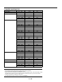
TABLE OF CONTENTS
1 INTRODUCTION
What's in the Box? ....................................................................................... E-1
Getting to Know Your G2150 Projector ........................................................ E-2
Attaching the lens hood cap to the lens hood
with the supplied string and rivet ........................................................ E-4
Carrying the Projector ........................................................................... E-4
Top Features ......................................................................................... E-5
Front Terminal Panel (Right) ................................................................. E-6
Front Terminal Panel (Left) .................................................................... E-7
Remote Control Features ..................................................................... E-8
Remote Control Precautions ....................................................... E-10
Remote Control Battery Installation ............................................. E-10
Operating Range for Wireless Remote Control ........................... E-10
Using the Remote Control in Wired Operation ............................ E-11
2 INSTALLATION
Setting Up Your GT2150 Projector ............................................................. E-12
Screen Size and Projection Distance ......................................................... E-12
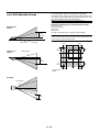
Lens Shift Adjustable Range ...................................................................... E-13
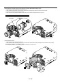
Optional Lens Installation ........................................................................... E-14
Setting up for Double Stacking in Link Mode ............................................. E-16
Projector Orientation .................................................................................. E-17
3 Basic Operation
Connecting the Power Cable and Turn on the Projector ............................ E-19
About Startup Screen ................................................................................ E-20
Set up the projector .................................................................................... E-21
Other adjustments ...................................................................................... E-22
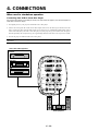
4 CONNECTIONS
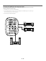
When used in standalone operation .......................................................... E-23
Connecting Your VCR Or Laser Disc Player ....................................... E-23
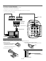
Connecting Your DVD Player with Component Output ........................ E-24
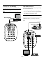
Connecting Your PC Or Macintosh Computer ..................................... E-25
Connecting a PC with DVI output ....................................................... E-26
Using OUTPUT Connectors ............................................................... E-26
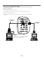
Connecting to a Single Workstation .................................................... E-27
Ferrite clamp core Installation ..................................................... E-27
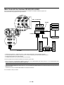
When Used with One Switcher (ISS-6020/ISS-6020G) ............................. E-28
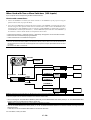
When Used with Two or More Switchers (100 Inputs) ............................... E-29
How to make connections ................................................................... E-29
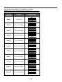
Set the DIP switch (S8601) of the Switcher as follows ....................... E-30
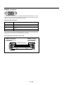
REMOTE 1 Connector ........................................................................ E-31
Operating Multiple Projector with Remote Control ..................................... E-33
Using the PC CONTROL connectors ......................................................... E-34
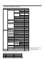
5 OPERATION
General Controls ........................................................................................ E-35
Using the Menus ........................................................................................ E-35
Customizing Basic/Custom Menu .............................................................. E-36
List of Direct Button Combinations ............................................................. E-37
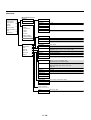
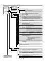
Menu Tree .................................................................................................. E-38
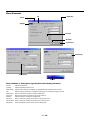
Menu Elements .......................................................................................... E-40
Menu Descriptions & Functions ................................................................. E-41
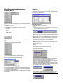
Source Select ............................................................................................. E-41
Switcher .............................................................................................. E-41
Entry List ............................................................................................. E-41
Entry Edit Command ................................................................... E-41
Selecting a new signal that is close to one of the listed
signals in horizontal and vertical frequency ............................. E-42
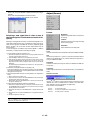
Adjust (Source) .......................................................................................... E-42
Picture ................................................................................................. E-42
Brightness ................................................................................... E-42
Contrast ....................................................................................... E-42
Saturation .................................................................................... E-42
Color ............................................................................................ E-42
Hue .............................................................................................. E-42
Sharpness ................................................................................... E-42
V-Aperture ................................................................................... E-42
Gamma Correction ...................................................................... E-42
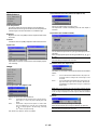
White Balance ..................................................................................... E-43
Color Temperature ....................................................................... E-43
Brightness R/G/B ......................................................................... E-43
Contrast R/G/B ............................................................................ E-43
Signal Level ................................................................................. E-43
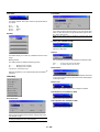
Image .................................................................................................. E-43
Pixel Adjust .................................................................................. E-43
Clock/Phase ............................................................................ E-43
Horizontal/Vertical Position .......................................................... E-43
Aspect Ratio ................................................................................ E-43
Resolution ................................................................................... E-43
Overscan ..................................................................................... E-43
Video Filter .................................................................................. E-44
Blanking ....................................................................................... E-44
Video Adj ............................................................................................ E-44
Noise Reduction .......................................................................... E-44
Color Matrix ................................................................................. E-44
Y/C Delay .................................................................................... E-44
Telecine ....................................................................................... E-44
Motion Select ............................................................................... E-44
Motion Level ................................................................................ E-44
YTR Adjustment .......................................................................... E-44
CTR Adjustment .......................................................................... E-44
Option Adj ........................................................................................... E-45
Clamp Timing .............................................................................. E-45
Sync Protection ........................................................................... E-45
VD Delay ..................................................................................... E-45
Signal Type ......................................................................................... E-45
Switcher .............................................................................................. E-45
Switcher Gain .............................................................................. E-45
Switcher Volume .......................................................................... E-45
Volume ....................................................................................................... E-45
Ref Adj ....................................................................................................... E-45
Keystone ............................................................................................. E-45
Lamp Mode ......................................................................................... E-46
Reference White Balance ................................................................... E-46
Factory Default ........................................................................................... E-46
Projector Options ....................................................................................... E-46
Timer ................................................................................................... E-46
On/Off Timer ................................................................................ E-46
Sleep Timer ................................................................................. E-47
Menu ................................................................................................... E-47
Page 1: ........................................................................................ E-47
Menu Mode/Language/Menu Display Time
Page 2: ........................................................................................ E-48
Display Select/Date Format/Date, Time Preset
Page 3: ........................................................................................ E-48
Message(No Input/Clean Filter)
Direct Button(Volume Bar/Keystone Bar)
Setup .................................................................................................. E-48
Page 1: ........................................................................................ E-48
Orientation/Background/S-Video Mode Select,
Remote Sensor
Page 2: ........................................................................................ E-49
Signal Select(RGB1/2) /Sync Termination(RGB1)
Page 3: ........................................................................................ E-49
Signal Select (Video 1/2 and S-Video) /
Signal Select (RGB Connector)
Page 4: ........................................................................................ E-49
Auto Adjust (RGB Only)/
Power Management/ ............................................................... E-50
Power Off Confirmation/Keystone Save/
Built-in Speaker/Lamp Off Mode/
Last Memory/User Name
Page 5: ........................................................................................ E-50
Communication Speed/Projector ID /
Default Source Select
Page 6: ........................................................................................ E-50
Clear Lamp Hour Meter/Clear Filter Usage
Link Mode .................................................................................... E-50
Switcher Control .......................................................................... E-51
Help ............................................................................................................ E-51
Contents ............................................................................................. E-51
Source Information ............................................................................. E-51
Projector Information .......................................................................... E-51
Link Mode .................................................................................... E-51
Test Pattern ................................................................................................ E-51
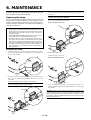
6 MAINTENANCE
Replacing the Lamp ................................................................................... E-52
Cleaning or Replacing the Filter ................................................................. E-53
Remplacement de la lampe ....................................................................... E-54
Nettoyage ou remplacement du filtre ......................................................... E-55
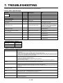
7 TROUBLESHOOTING
Power / Status Light Messages .................................................................. E-56
Lamp Light Messages ................................................................................ E-56
Common Problems & Solutions ................................................................. E-56
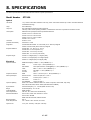
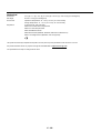
8 SPECIFICATIONS
Optical/Electrical ........................................................................................ E-57
Mechanical ................................................................................................. E-58
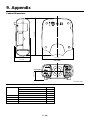
9 Appendix
Cabinet Dimensions ................................................................................... E-59
Optional Accessories ................................................................................. E-59
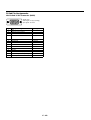
D-Sub Pin Assignments ............................................................................. E-60
Compatible Input Signal List ...................................................................... E-61
List of Menu Items Available on Link Mode ................................................ E-62
PC Control Codes ...................................................................................... E-63
Cable Connection ...................................................................................... E-63
Gravity Stack .............................................................................................. E-63
E – viii
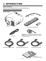
1. INTRODUCTION
What's in the Box?
Make sure your box contains everything listed. If any pieces are missing, contact your dealer.
Please save the original box and packing materials if you ever need to ship your GT2150 Projector.
NOTE: Lenses are optional. Order lenses from your NEC dealer.
N
U
ENTE R
CEL
T
C
LE
E
S
CAN
E
C
R
U
O
S
P
M
LA
T
TO S
U
A DJU
A
S
TU
TA
S
N
O
D
N
TA
/S
R
E
W
O
P
Y
B
GT2150 Projector
S
U
C
FO
M
O
ZO
FT
LE
P
U
S
N
LE
T
IF
H
S
N
W
O
D
T
H
IG
R
ME
String and rivet
Lens hood cap
Remote control and batteries (AAA x 2)
Remote cable
Power cable for Europe (AC 220-240V)
Ferrite clamp cores for a commercially available BNC cable and DVI
cable (⳯2)
(For RGB1 connector and DVI DIGITAL Input connector. See page E-27
for installation instructions.)
Power cable for North America (AC 120V)
Power cable for Japan (AC 100V)
User’s manuals
(Japanese and English/German)
E–1
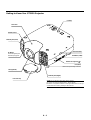
Getting to Know Your GT2150 Projector
Controls
T
C
LE
E
S
N
U
ENTER
O
U
R
CEL
S
CAN
C
E
LA
M
P
S
T
TO S
U U
A DJ
A
TA
TU
S
O
N
/S
P
O
TA
N
W
D
E
R
B
Y
Lens hood
S
U
C
FO
M
O
ZO
FT
LE
P
U
S
N
LE
T
IF
H
S
N
W
O
D
T
H
IG
R
ME
Remote sensor
Terminal panel (Left)
PC
CA
RD
IN
PC
CO
NT
RO
L
RE
MO
TE
IN
RE
MO
TE
2
OU
T
OU
T
1
SC
,T
RIG
GE
R
DVI
AC INPUT
Connect the supplied power
cable’s three-pin plug here.
DIG
Remote sensor
ITAL
L/M
AC
IN
DVI
OUTP
DIG
R
L/M
ANAL
ONO
ITAL
UT
ONO
R
OG
RG
RG
Ventilation (outlet)
B2
B1
R/Cr
VIDE
G/Y
O1
B/Cb
VIDE
O2
L/M
L/M
ONO
H/HV
R
V
Built-in Security Slot (
ONO
R
S-VI
L/M
DEO
)*
ONO
R
AUDI
OO
UT
Foot (four)
Rotate to fine-adjust the height of each foot.
Lens (optional)
Terminal panel (Right)
Lens hood cap
*NOTE: Slot for Kensington MicroSaver Security System
This security slot supports the MicroSaver® Security System.
MicroSaver® is a registered trademark of Kensington Microware Inc. The logo
is trademarked and owned by Kensington Microware Inc.
E–2
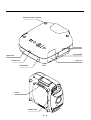
Depression for foot (4 locations)
FO
C
U
S
P
O
M
FT
U
LE
ZO
LE
N
S
S
H
IF
T
D
O
R
N
IG
W
H
T
ME
N
U
S
LE
C
T
ENTER
E
S
O
U
R
C
CEL
CAN
E
LA
P
TA
T
S
TO S
U U
A DJ
A
M
TU
S
O
N
O
N
E
D
W
TA
P
/S
Remote sensor
B
R
Y
Speaker (Left)
Carrying handle
Lamp cover
Remote sensor
Speaker (Right)
IN
PC CARD
IN
REMOTE
2
OUT
DVI
MONITOR
RGB 2
R
L/MONO
R/Cr
VIDEO
2
1
L/MONO
OUT
VIDEO
R
RGB 1
G/Y
L/MONO
H/HV
R
L/MONO
S-VIDEO
R
B/Cb
V
L/MONO
R
AUDIO
OUT
E–3
OUT
GER
SC. TRIG
Ventilation (inlet)
TROL
PC CON
1
REMOTE
Air filter
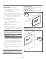
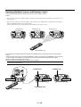
Attaching the lens hood cap to the lens hood with the supplied string and rivet
Lens hood cap
1. Thread the string through the hole on the lens hood cap.
String
2. Use the rivet to attach the string to the bottom of the projector.
Rivet
DVI
R
R/Cr
L/MON
O
L/MON
O
MONIT
OR OU
T
RGB 2
VIDEO
2
VIDEO
1
R
RGB 1
G/Y
L/MON
O R
RGB 1
G/Y
V
H/HV
L/MON
O R
B/Cb
R
UP
LENS SHIFT
FOCUS
ZOOM
LEFT
DOWN
RIGHT
ENT
E–4
STATUS
LAMP
NC
CA
ER
SELECT
E
L
MENU
POWER
AUTO
ADJUST
ON/STAND BY
SOURCE
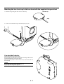
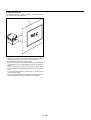
CAUTION:
Do not put the projector on its side when the lamp is on.
Doing so may cause damage to the projector.
R
AUDIO
OUT
Always carry your projector by the handle.
Ensure that the power cable and any other cables connecting to video sources
are disconnected before moving the projector.
When moving the projector or when it is not in use, cover the lens with the
lens hood cap.
V
L/MON
O
R
AUDIO
OUT
B/Cb
L/MON
O
L/MON
O
R
S-VIDE
O
H/HV
L/MON
O
S-VIDE
O
Carrying the Projector
Top Features
8
FO
C
4
U
S
5
M
P
O
FT
U
LE
ZO
6
LE
N
3
S
S
H
IF
T
2
D
O
IG
N
H
T
ME
U
N
9
R
W
10
S
E
LE
ENTER
C
T
O
NCEL
U
R
CA
S
C
7
E
LA
P
T
TO S
U U
A DJ
A
M
S
TA
TU
S
O
N
/S
P
D
B
R
E
N
W
TA
O
Y
11
12
1. Power Button (ON / STAND BY) (
)
Use this button to turn the power on and off when the power is supplied and the projector is in standby mode.
NOTE: To turn off the projector, press and hold this button for a minimum of
two seconds.
2. Auto Adjust Button (RGB only)
Use this button to adjust Position-H/V and Pixel Clock for an optimal
picture. Some signals may not be displayed correctly or take time to
switch between sources.
3. Source Button
Use this button to select a video source such as a PC, VCR or DVD
player.
Each time this button is pressed, the input source will change as follows:
RGB1 → RGB2 → DVI (DIGITAL) → Video1 → Video2 → S-Video
If no input signal is present, the input will be skipped.
4. Menu Button
Displays the menu.
5. Select ▲▼䊴 䊳 / Volume (+) (-) Buttons
▲▼: Use these buttons to select the menu of the item you wish to
adjust.
When no menus appear, these buttons work as a volume control.
䊴 䊳:
Use these buttons to change the level of a selected menu item.
A press of the 䊳 button executes the selection.
13
1
8 Lens Shift Button
Adjust the lens offset by shifting the projected image position horizontally and / or vertically.
9 Zoom Button
Zoom the lens in and out.
10 Focus Button
Adjust the lens focus.
11. Lamp Remaining Indicator
Indicates the lamp remaining amount. See the Lamp Light Messages
on page E-56 for more details.
12. Status Indicator
When this is lit red (orange in Eco mode) continually, it‘s warning you
that the projection lamp has reached the end of its usable life (1500
hours in Normal mode and up to 2000 hours in Eco mode). After this
light appears, it is advisable to replace the projection lamp as soon as
possible. (See page E-52). In addition the message "The lamp has
reached the end of its usable life. Please replace the lamp." appears
continually until the lamp is replaced.
If the projector is in Eco mode or something out of the ordinary takes
place, this indicator is lit or blinks. For example, If this light blinks red
rapidly, it indicates that the lamp cover is not attached properly or the
projector is overheated.
See the Power / Status Light Messages on page E-56 for more details.
13. Power Indicator
When this indicator is green, the projector is on; when the indicator is
orange, it is in standby mode.
6. Enter Button
Executes your menu selection and activates items selected from the
menu.
7. Cancel Button
Press this button to exit “Menus”. Press this button to return the adjustments to the last condition while you are in the adjustment or setting
menu.
E–5
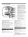
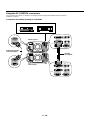
Front Terminal Panel (Right)
DVI
DIG
ITA
L
L/M
1
DVI
OUT
DIG
2
ON
O
R
LOG
RG
RG
4
B2
B1
R/C
VID
R
L
L/M
5
O
ITA
PUT
ANA
ON
EO
3
r
G/Y
1
8
B/C
VID
9
10
11
EO
2
L/M
L/M
ON
ON
H/H
O
6
b
V
R
V
7
O
R
L/M
S-V
IDE
O
ON
O
R
13
AUD
IO O
UT
12
5. DVI DIGITAL OUTPUT Connector (DVI-D)
This connector is used for double stacking.
Use a DVI-D cable (option) to connect the DIGITAL
OUTPUT connector of a projector to the DVI DIGITAL input of the following projector until all the projectors are connected.
ANALOG OUTPUT Connector (Mini D-Sub 15 pin)
You can use this connector to loop your computer
image an external monitor from either the RGB 1 or
RGB 2 input source.
6. RGB 1 Input Connectors (BNC)
Connect R,G,B,H (Horizontal sync) and V (Vertical
sync) outputs of external equipment such as the NEC
ISS-6020Switcher.
If using a component with a combined sync (SYNC)
output, connect it to the H/V terminal. When using
luminance and color-difference signals of HDTV and
DVD, connect Pr/Cr to the R,Y to the G and Pb/Cb
to the B input of the projector.
7. RGB 1 Audio Input Jacks (RCA)
L/MONO
This is your left channel audio input for stereo sound
coming from the RGB Input 1 source.
This also serves as your monaural audio input.
R
This is your right channel audio input for stereo sound
from the RGB Input 1 source.
8. VIDEO 1 Input Connector (BNC)
Connect a VCR, DVD player, laser disc player, or
document camera here to project video.
1. DVI DIGITAL Input Connector (DVI-D)
This connector can be used to accept digital signal output from a computer with a DVI connector.
9. VIDEO 2 Input Connector (RCA)
Connect a VCR, DVD player, laser disc player, or document camera
here to project video.
2. DVI DIGITAL Audio Input Jacks (RCA)
These are the left channel and the right audio inputs for stereo sound
coming from the equipment connected to a computer with DVI output.
L/MONO
This is your left channel audio input for stereo sound from the equipment connected to a computer with DVI output.
The L/MONO jack also serves as your monaural audio input.
R
This is your right channel audio input for stereo sound from the equipment connected to a computer with DVI output.
10. VIDEO Audio Input Jacks (RCA)
L/MONO
This is your left channel audio input for stereo sound coming from the
VIDEO 1 or VIDEO 2 source.
This also serves as your monaural audio input.
R
This is your right channel audio input for stereo sound from the VIDEO
1 or VIDEO 2 source.
3. RGB 2 Connector (Mini D-Sub 15 pin)
Connect your PC, Macintosh, DVD player with Y/Cb/Cr outputs or other
RGB equipment. The optional Component V. Cable is required for Y/
Cb/ Cr input connection.
NOTE: The RGB2 connector does not support the Switcher Control mode.
4. RGB 2 Audio Input Jacks (RCA)
L/MONO
This is your left channel audio input for stereo sound coming from the
RGB Input 2 source.
This also serves as your monaural audio input.
R
This is your right channel audio input for stereo sound from the RGB
Input 2 source.
11. S-VIDEO Input Connector (DIN 4 pin)
Here is where you connect the S-Video input from an external source
such as a VCR or laser disc player.
NOTE: S-Video provides more vivid color and higher resolution than the traditional composite video format.
12. S-VIDEO Audio Input Jacks (RCA)
L/MONO
This is your left channel audio input for stereo sound coming from the
S-VIDEO source.
This also serves as your monaural audio input.
R
This is your right channel audio input for stereo sound from the SVIDEO source.
13. AUDIO OUT Jacks (RCA)
You can use this connector to output sound from the currently selected
input source (RGB 1, RGB 2, DVI (DIGITAL), VIDEO 1, VIDEO 2 or SVIDEO). Output sound level can be adjusted in accordance with the
sound level of the internal speaker.
E–6
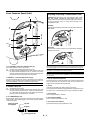
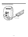
Front Terminal Panel (Left)
Inserting or Ejecting a CompactFlash Card
CAUTION: DO NOT EJECT THE CompactFlash CARD, TURN
OFF THE POWER, OR UNPLUG THE POWER CABLE of the
projector while the PC card access indicator light shows that data
is being accessed. Doing so could cause damage to the
CompactFlash card.
9
7
PC
Inserting
Insert the CompactFlash card into PC Card Slot with its TOP FACING DOWN.
D
CAR
8
IN
IN
1
PC
L
TRO
CON
OTE
REM
2
5
3
D
CAR
PC
Bottom
IN
IN
OUT
OUT
4
2
L
TRO
CON
PC
GER
TRIG
SC,
OTE
REM
Removing
Press the PC Card Eject button. The CompactFlash card ejects
partially, then remove.
1
AC
OTE
REM
2
IN
D
CAR
PC
6
IN
IN
1. PC CONTROL Connectors (Mini D-Sub 9 pin)
For system expansion such as PC-Control.
IN:
connect to the external equipment such as PC.
OUT: for daisy-chaining multiple projectors and operating them with
the same external equipment. To do so, connect to a second
projector’ s IN terminal to relay the input at the IN terminal of the
first projector until all the projectors are connected.
2. REMOTE 1 Connector (Mini D-Sub 15 pin)
This terminal allows external control of the projector from either the
Switcher or from an external control. When the Switcher is used, connect to the REMOTE 1 terminal on the back of the Switcher.
NOTE: This projector is compatible with the ISS-6020 Switcher.
3. REMOTE 2 Mini Jacks
IN:
wired remote control input.
OUT: for daisy-chaining multiple projectors and operating them with
the same remote control. To do so, connect to a second projector’ s IN terminal to relay the input at the IN terminal of the first
projector until all the projectors are connected.
4. SC. TRIGGER Mini Jack
Screen Trigger- When the GT2150 is powered ON the screen trigger
output sends a low voltage trigger to the screen controller and the
screen will go down.
Stereo mini cable
(not supplied)
Tip (12V)
When the GT2150 is powered OFF the screen trigger stops sending a
low voltage trigger to the screen controller and the screen will go up.
NOTE: Screen Controllers are supplied and supported by screen manufactures.
This option is not included with the GT2150 projector.
NOTE: Do not use this jack for anything other than intended use. Connecting
the wired remote control to the SC. TRIGGER Mini Jack causes damage to the
remote control.
5. Slot for LAN Board (Optional)
Use this connector to control the projector on a LAN. The optional LAN
kit is required when this connector is used. See the instructions included with the optional LAN kit (GT50LAN).
6. AC IN
Connect the supplied power cable’s three-pin plug here.
Three types of power cable are supplied with this LCD projector: threepin type for U. S. A. and Canada. Two-pin type for Europe and Japan.
7. PC Card Slot
Insert a CompactFlash™ card here.
8. PC Card Eject Button
Press to eject a CompactFlash™ card.
9. PC Card Access Indicator
Lights while accessing a CompactFlash™ card.
Ring (0V)
Sleave (ground. 0V)
E–7
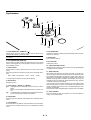
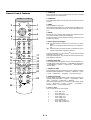
1. POWER ON
Press this button to turn on the projector when the power is supplied
and the projector is in standby mode.
Remote Control Features
2. POWER OFF
Press and hold this button for a minimum of two seconds to turn off the
projector.
POWER
OFF
ON
1
2
MENU
5
-
BS
ADDRESS
+
3
ENTER
4
6
7
ADJUST
IMAGE
PICTURE WHITE BAL. PROJECTOR
9
10
ABC
DEF
GHI
1
2
3
JKL
MNO
PQR
4
5
6
STU
VWX
YZ/
7
8
9
,.
UNDO
CANCEL
INFO.
TEST
21
22
AUTO
LENS
MUTE
SHUTTER
20
HELP
POSITION PIXEL
PICTURE SOUND
OSD
KEYSTONE AMPLITUDE ENTRYLIST
R
G
B
11
14
15
16
18
19
23
MAGNIFY
+
+
-
-
25
24
FOCUS
26
ZOOM
LENS
CTL
4. ENTER
Executes the menu selection and activates items selected from the
menu. When the slider or dialog box is displayed:
Pressing this button confirms adjustments/setting and returns to the
previous menu display.
5. Select (Up/Down/Left/Right)
▲▼: Use these buttons to select the menu of the item you wish to
adjust.
When no menus appear, these buttons work as a volume control.
䊴 䊳: Use these buttons to change the level of a selected menu item.
A press of the 䊳 button executes the selection.
0
12
13
17
8
3. MENU
Press to display the main menu.
While pressing and holding CTL, press this button to display the Remote Control ID dialog box to specify the remote control ID. See page
E-33.
Pressing and holding CTL, then pressing 䊴 button works as a Back
Space key in the entry screen.
Pressing and holding CTL, then pressing this button moves the menu,
slider, toolbar or dialog box.
6. ADJUST WHITE BAL
Press to display the Color adjustment screen. Pressing this button sequentially selects "Color Temperature" → "White Balance - Brightness"
→ "White Balance - Contrast" → "Signal Level" → "Ref.White Bal" →
"Switcher-Gain".
7. ADJUST PICTURE
Press to display the Picture adjustment screen. Pressing this button
sequentially selects "Brightness" → "Contrast" → "Saturation" → "Color"
→ "Hue" → "Sharpness" → "V-Aperture" → "Gamma Correction".
8. IMAGE/PROJECTOR
Press to display the Image Option screen. Pressing this button sequentially selects "Pixel Adjust" → "Position" → "Aspect Ratio" → "Resolution" → "Overscan" → "Video Filter" → "Blanking".
While pressing and holding CTL, pressing this button rotates "On/Off
Timer" → "Sleep Timer" → "Menu" → "Setup" → "Link Mode" →
"Switcher Control" → "LAN mode"(optional).
9. Source / Input
Press to select input or to name a signal.
1
2
3
4
5
6
7
8
E–8
..................
..................
..................
..................
..................
..................
..................
..................
Selects RGB 1 input.
Selects RGB 2 input.
Selects DVI (DIGITAL) input.
Selects VIDEO 1 input.
Selects VIDEO 2 input.
Selects S-VIDEO input.
Selects RGB1 (VIDEO) input
Selects RGB1 (S-VIDEO) input
27. Remote Jack
Connect your remote control cable here for wired operation.
18. MUTE SOUND
Turns off the sound for a short period of time. Press again to restore
the sound.
19. MUTE OSD
Press to turn off the on-screen display. Press again to restore the onscreen display.
NOTE: You can also turn off the on-screen display forcefully by pressing and
holding CTL and then pressing MUTE OSD (Forced On-Screen Mute Mode) ;
doing this again restores it. In this case any adjustment will still change the
projector's memory settings. This mode is available even when input is switched
to another or the power is turned off the main power.
20. MUTE PICTURE
Press to turn off the picture for a short period of time. Press again to
restore the picture.
21. KEYSTONE (R)
Press to display the Keystone Correction screen.
When the test pattern is displayed, while pressing and holding CTL,
pressing this button displays a red test pattern.
22. AMPLITUDE (G)
Service personnel only.
When the test pattern is displayed, while pressing and holding CTL,
pressing this button displays a green test pattern.
23. ENTRY LIST (B)
Press to display the Entry List screen.
When the test pattern is displayed, while pressing and holding CTL,
pressing this button displays a blue test pattern.
E–9
TU
S
4
2
1
L
JK
E
D
H
A
S
B
-
IC C
P AB
W
E
TU
JU
D
+
F
F
O
17. POSITION
Press to display the Blanking screen; press again to display the Position screen.
While pressing and holding CTL, pressing this button displays the Lens
Shift adjustment screen.
27
28
R
T
S
DR
AD
U
N
E
M
N
O
R
E
W
O
P
15. PIXEL
Displays the Position/Clock screen to adjust the clock and phase.
A
B
E
IT F
G
A
IM
ES
S
R
TE
N
E
14. HELP
Provides online help.
16. AUTO (RGB only)
Press to adjust Position-H/V and Pixel Clock for an optimal picture.
N
M
JE
G
28. Infrared Transmitter
Direct the remote control toward the remote sensor on the projector
cabinet.
E
13. TEST
Press to display the test pattern. Pressing this button sequentially selects six test patterns.
26. CTL
Used in conjunction with other buttons, similar to a shift key on a computer.
O
12. INFO
Displays the "Source Information" or "Projector Information" window.
This button toggles between these two windows.
25. MAGNIFY/ZOOM (+/–)
Magnify the size of a target portion.
While pressing and holding CTL, pressing this button allows you to
zoom the lens in and out.
PR
11. CANCEL
Press to exit the menu.
Press this button with CTL to return to the previous menu without closing adjustment/setting screen while the menus appear. This feature
allows you to adjust or set several items concurrently.
24. FOCUS (+/–)
While pressing and holding CTL, pressing this button allows you to
adjust the lens focus.
L.
10. UNDO
Press to return the adjustments and settings to the previous condition.
While pressing and holding CTL, pressing this button clears the entire
menus or adjustment/setting screen. At this time the adjustments/settings are stored in memory except the items on the setting screen with
"OK" and "Cancel" buttons such as the Menu and the Setup screen.
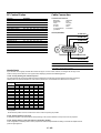
Remote Control Precautions
Operating Range for Wireless Remote Control
• The remote control system may not function when direct sunlight or
strong illumination strikes the remote control sensor of the main unit,
or when there is an obstacle in the path.
• When remote control buttons are pressed and held, projector’s function keys may not operate.
• Do not subject to strong shock.
• Do not allow water or other liquid to splash on the remote control. If
the remote control gets wet, wipe it dry immediately.
• Avoid exposure to heat and steam.
• Remove the batteries from the remote control when the remote control is not going to be used for a long period.
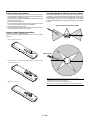
The infrared signal operates by line-of-sight up to a distance of approximately 7m (20 feet) and a 60 degree angle of the remote sensor.
The projector will not function if there are objects between the remote
sensor and the remote control or if strong light falls on the remote
sensor. Weak batteries will also prevent the projector from operating
properly.
Remote sensors on the projector cabinet
30˚
Remote Control Battery Installation
Installing the Remote Control Batteries
When it comes time to replace the batteries, two "AAA" type will be
required.
7m
30˚
Side View
1. Press and open the cover.
Remote control
2. Align and insert the batteries according to the (+) and (-) indications inside the case.
3. Replace the cover.
7m
NOTE: You cannot operate the projector using the remote control if:
• The remote control ID is not set to [None].
• The remote ID is not the same as the projector ID.
See page E-33 for setting remote ID and page E-50 for setting projector ID.
E – 10
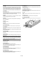
Using the Remote Control in Wired Operation
Connect one end of the supplied remote cable to the REMOTE 2 IN
mini jack and the other end to the remote jack on the remote control.
IN
Terminal panel (Left)
E – 11
T
,.
7
TU
S
M
4
2
L
1
JK
D
R
TU
IC C
P AB
E
W
S
B
E
N
8
X
W
V
5
O
N
G
E
L.
A
B
E
IT F
H
T
S
JU
D
A
+
F
F
O
AC IN
S
O
D
Z
Y
6
R
Q
P
3
R
I
O
H
CT
JE
O
PR
E
G
A
IM
R
S
TE
ES
N
E
DR
AD
U
N
E
M
N
O
R
E
W
O
P
Remote cable (supplied)
0
SC. TRIGGER
U
REMOTE 1
C
OUT
N
OUT
A
REMOTE
2
C
PC CONTROL
9
IN
/
IN
FO
E
.
L
P
IX
H
E
E
L
LP
A
U
TO
D T
PC CARD
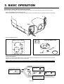
2. INSTALLATION
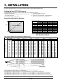
This section describes how to set up your GT2150 projector and how to connect video and audio sources.
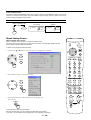
Setting Up Your GT2150 Projector
Your GT2150 Projector is simple to set up and use. But before you get started, you must first:
1. Determine the image size
4. Connect the supplied power cable.
2. Set up a screen or select a non-glossy white wall onto which you
5. Set up the projector.
can project your image.
6. Connect a PC, VCR, DVD player, or other equipment.
3. Install the optional lens to the projector.
7. Make settings or adjustments on the projector.
Screen Size and Projection Distance
Applicable lens and throw distance/ List of screen sizes
List of Screen Sizes
Screen size
Height
Width (H)
Height (V)
m
inch
m
inch
0.8
31.5
0.6
23.6
1.2
47.2
0.9
35.4
1.6
63.0
1.2
47.2
2.0
78.7
1.5
59.1
2.4
94.5
1.8
70.9
3.0
118.1
2.3
90.6
4.1
161.4
3.0
118.1
5.1
200.8
3.8
149.6
6.1
240.2
4.6
181.1
8.1
318.9
6.1
240.2
10.2
401.6
7.6
299.2
Screen width H (m)= Screen Diagonal (4:3)⳯4/5⳯0.0254
Screen height V (m)= Screen Diagonal (4:3)⳯3/5⳯0.0254
Screen width H (inch)= Screen size⳯4/5
Screen height V (inch)= Screen size⳯3/5
40"
60"
80"
100"
120"
150"
200"
250"
300"
400"
500"
Formulas:
Screen size (Diagonal)
Width
Table of Throw Distances and Screen Sizes for Optional Lenses
Screen Size (Diagonal)
LENS
Model
Magnification
40"
60"
67"
72"
80"
84"
90"
100"
120"
150"
180"
200"
210"
240"
250"
270"
300"
400"
500"
GT10RL
1.0
inch
m
31.5
0.8
47.2
1.2
51.2
1.3
55.1
1.4
63.0
1.6
66.9
1.7
70.9
1.8
78.7
2.0
94.5
2.4
118.1
3.0
145.7
3.7
161.4
4.1
169.3
4.3
192.9
4.9
200.8
5.1
220.5
5.6
240.2
6.1
-
GT13ZL
1.3 – 1.6
m
1.1
1.6
1.7
1.9
2.1
2.2
2.3
2.6
3.2
4.0
4.7
5.3
5.5
6.3
6.6
7.1
7.9
-
inch
43.3
63.0
66.9
74.8
82.7
86.6
90.6
102.4
126.0
157.5
185.0
208.7
216.5
248.0
259.8
279.5
311.0
-
–
–
–
–
–
–
–
–
–
–
–
–
–
–
–
–
–
–
–
GT19ZL
1.8 – 2.4
m
1.3
2.0
2.1
2.3
2.6
2.7
2.9
3.3
3.9
4.9
5.8
6.5
6.8
7.8
8.1
8.8
9.8
-
inch
51.2
78.7
82.7
90.6
102.4
106.3
114.2
129.9
153.5
192.9
228.3
255.9
267.7
307.1
318.9
346.5
385.8
-
m
1.5
2.2
2.5
2.6
2.9
3.1
3.3
3.7
4.4
5.5
6.7
7.3
7.9
9.0
9.1
10.1
11.0
-
GT10RL (H⳯1.0)
inch
59.1
86.6
98.4
102.4
114.2
122.0
129.9
145.7
173.2
216.5
263.8
287.4
311.0
354.3
358.3
397.6
433.1
-
–
–
–
–
–
–
–
–
–
–
–
–
–
–
–
–
–
–
–
GT34ZL
3.4 – 5.2
m
2.0
2.9
3.2
3.5
3.9
4.1
4.3
4.9
5.9
7.3
8.8
9.8
10.3
11.7
12.2
13.2
14.6
-
inch
78.7
114.2
126.0
137.8
153.5
161.4
169.3
192.9
232.3
287.4
346.5
385.8
405.5
460.6
480.3
519.7
574.8
-
m
5.5
5.9
6.3
6.9
8.3
10.4
12.8
13.8
15.0
17.1
17.3
19.3
20.7
27.6
34.5
inch
216.5
232.3
248.0
271.7
326.8
409.4
503.9
543.3
590.6
673.2
681.1
759.8
815.0
1086.6
1358.3
–
–
–
–
–
–
–
–
–
–
–
–
–
–
–
–
–
–
–
GT34ZL (H⳯3.4) – (H⳯5.2)
Throw distance
GT13ZL (H⳯1.3) – (H⳯1.6)
GT19ZL (H⳯1.8) – (H⳯2.4)
For screen sizes between 40” and 500” not indicated on the above table, use formulas below.
Projection Distance = Screen Width (H)⳯Lens Magnification
Throw distance for GT10RL lens (m/inch) =H⳯1.0 (For H between 0.8 m / 31.5 inch and 6.1 m / 240.2 inch)
Throw distance for GT13ZL lens (m/inch) =H⳯1.3 through H⳯1.6 (For H between 1.1 m / 43.3 inch and 9.8 m / 385.8 inch)
Throw distance for GT19ZL lens (m/inch) =H⳯1.8 through H⳯2.4 (For H between 1.5 m / 59 inch and 14.6 m / 574.8 inch)
Throw distance for GT34ZL lens (m/inch) =H⳯3.4 through H⳯5.2 (For H between 5.5 m / 216.5 inch and 52.8 m / 2078.7 inch)
NOTE: Distances may vary +/-5%.
E – 12
m
8.5
9.0
9.6
10.6
12.7
15.8
19.3
21.1
22.6
25.8
26.4
29.1
31.7
42.3
52.8
inch
334.6
354.3
378.0
417.3
500.0
622.0
759.8
830.7
889.8
1015.7
1039.4
1145.7
1248.0
1665.4
2078.7
Lens Shift Range for Desktop and Ceiling Mount Application
The diagram below shows the location of the image position in the
lens. The lens can be shifted within the shaded area as shown using
the normal projection position as a starting point.
NOTE: Lens shift feature is not available on GT10RL(fixed lens).
Lens Shift Adjustable Range
Maximum Possible Range for GT19ZL/GT34ZL (GT13ZL):
Up: 0.5 V (0.43V)
Down: 0.5 V (0.43V)
Right: 0.25 H
Left: 0.25 H
(H: width of projected image, V: height of projected image)
Desktop/Front
Vertical
0.5V
(0.43V)
NOTE: If lens is shifted in two directions combined, maximum range in either
direction cannot be obtained due to rounded off area near edge of lens. (example: shift up and right) See diagram below.
Normal position
0.25H
Ceiling/Front
Vertical
0.25H
0.5V
(0.43V)
0.5V
(0.43V)
0.5V
(0.43V)
0.5V
(0.43V)
Normal position
0.5V
(0.43V)
Normal projection
position
Horizontal
Normal position
0.25H
E – 13
0.25H
0.25H
Optional Lens Installation
This section describes how to install the lens.
Before installation
* Determine the optional lens to be used to obtain a desired projection distance. There are four optional lenses available:
GT10RL (Fixed short throw lens)
GT19ZL, GT13ZL and GT34ZL (Zoom lens)
* Press the power button (ON/STAND BY) on the projector or POWER OFF button on the remote control, wait three minutes for the cooling fan to stop, then
disconnect the power cable.
Check that the projector has cooled off sufficiently before proceeding.
CAUTION
* The projector and lens contain high-precision parts. Do not induce shock to the projector or the lens.
* Do not touch the lens surface. Doing so can degrade the optical performance.
Preparation: Tools needed for installation:
A hexagonal driver and dust-protective sheets are supplied with the optional lens.
1. Remove the lens hood cap and lens hood.
1 Press and hold the catches on both ends of the lens hood cap, and 2 then remove it.
3 Loosen the 4 screws on the lens hood using the hexagonal driver until the hexagonal driver goes into a freewheeling condition and 4 remove
the lens hood. The 4 screws are not removable.
PC
CA
RD
IN
Lens hood
PC
3
IN
CO
NT
RO
L
RE
MO
TE
2
OU
T
OU
T
RE
MOT
E1
SC
, TR
IG
GE
R
AC
DVI
DIG
ITA
L
IN
Lens hood cap
L/M
ON
O
DVI
DIG
ITA
L
OUTPU
T
R
L/M
ON
O
ANAL
OG
R
RG
B2
RG
B1
R/C
r
3
VID
EO
G/Y
1
B/C
b
3
VID
EO
2
L/M
ON
O
H/H
V
R
V
L/M
ON
O
R
S-V
IDE
O
4
1
L/M
ON
O
R
AUDIO
OU
T
3
2
1
2. Remove the dust-protective sheet and replace with the new one.
1 Remove the dust-protective sheet on the back of the lens hood. 2 Replace it with the dust-protective sheet included with the optional lens.
Place the dust-protective sheet with the two holes side up while warping it. Be careful not to fold the sheet.
1
Dust-protective sheet
(included with the optional lens)
Dust-protective sheet
(on the projector)
Hole
2
Hole
Side with aluminum
E – 14
Completed
3. Mount the lens unit on the projector and connect the extension cable attached to the projector.
1 Remove the lens cap from the rear end of the lens unit.
2 Insert the lens unit so that the 4 screws on the lens unit are properly lined up with the 4 holes on the lens mount.
3 Secure the 4 screws using the hexagonal driver.
4 Insert the connector of the lens unit fully into the socket of the extension cable attached to the projector.
Y
B
R
E
W
O
P
D
N
TA
/S
T
C
LE
E
S
N
W
O
D
M
O
ZO
S
U
C
FO
FT
LE
P
U
S
U
C
FO
S
N
LE
T
IF
H
S
M
O
ZO
FT
LE
T
H
IG
R
S
N
LE
ME
P
U
ENTE R
E
C
R
U
O
S
U
N
W
O
D
T
H
IG
R
ME
T
IF
H
S
N
U
N
P
M
LA
T
TO S
U
A DJU
A
S
TU
TA
S
N
O
P
M
LA
CEL
T
C
LE
E
S
ENTE R
E
C
R
U
O
S
CAN
1
CEL
Lens mount
CAN
T
TO S
U
A DJU
A
S
TU
TA
S
N
O
D
N
TA
/S
R
E
W
O
P
Y
B
NOTE: Leave the front lens cap for protection while mounting the lens unit.
IN
PC
IN
CO
NT
RO
L
IN
PC
RE
MO
TE
2
OU
T
2
OU
T
RE
MOT
E1
CO
IN
NT
OU
RO
L
RE
MO
TE
2
T
OU
SC
, TR
IG
GE
R
RE
MOT
, TR
IN
AC
VI
L/M
ON
O
T
E1
SC
AC
IG
GE
R
IN
VI
R
L/M
MO
NIT
OR
L/M
ON
O
3
R
OU
T
RG
B1
RG
B2
L/M
MO
OR
RG
G/Y
1
R/C
VID
2
ON
ON
O
H/H
V
L/M
ON
O
R
O
R
T
B2
B2
B/C
b
VID
EO
OU
RG
R/C
r
VID
EO
NIT
EO
r
G/Y
1
B/C
R
b
V
VID
L/M
ON
O
EO
2
L/M
H/H
ON
O
V
R
V
R
L/M
ON
O
S-V
IDE
O
L/M
R
ON
4
O
R
S-V
AUDIO
L/M
IDE
ON
O
O
R
OU
T
AUDIO
OU
T
4. Reinstall the lens hood.
R
E
W
O
P
S
TU
TA
S
P
M
LA
T
TO S
U
A DJU
A
N
N
U
U
T
C
LE
E
S
ENTE R
T
C
LE
E
S
ENTE R
E
C
R
CEL
U
CAN
O
CEL
S
CAN
E
C
R
U
O
S
LA
M
P
S
T
TO S
U
A DJU
A
TA
TU
S
O
N
N
O
/S
P
O
TA
N
W
D
E
D
N
TA
/S
R
B
Y
Y
B
1 Remove the front lens cap from the lens unit.
2 Insert the lens hood so that the grooves on the 4 corners of the lens hood are properly lined up with the 4 catches on the projector.
3 Secure the 4 screws using the hexagonal driver.
This completes installation. 4 If necessary, put the lens hood cap on the lens hood.
ME
T
IF
H
S
OU
S
U
C
FO
PC
MOT
RE
MO
TE
2
IN
NT
OU
3
T
E1
SC
, TR
IG
GE
R
DVI
DIG
ITA
RO
DVI
IN
DIG
ITA
OUTPU
T
ON
ON
O
MOT
T
E1
SC
AC
, TR
IG
GE
R
DVI
DIG
ITA
L
IN
EO
R
RG
B2
B2
RG
B1
3
r
G/Y
1
2
L/M
L/M
H/H
ON
ON
O
3
b
V
R
V
R/C
r
VID
EO
G/Y
1
B/C
b
VID
EO
2
L/M
ON
O
L/M
IDE
O
H/H
V
R
V
L/M
ON
O
O
R
S-V
R
L/M
ON
O
ANAL
OG
R
B1
EO
L/M
ON
O
DVI
DIG
ITA
L
OUTPU
T
B/C
VID
RE
R
OG
R/C
VID
OU
O
RG
RG
RE
MO
TE
2
L
L/M
ANAL
L
T
L
L/M
AC
1
CO
L
T
OU
RE
CA
RD
IN
RO
R
ON
S-V
IDE
O
O
R
AUDIO
OU
2
T
M
O
ZO
P
U
M
O
ZO
S
U
C
FO
PC
CA
RD
IN
NT
FT
LE
S
N
LE
T
IF
H
S
S
N
LE
FT
LE
P
U
CO
N
W
O
D
T
H
IG
R
N
W
O
D
T
H
IG
R
ME
PC
IN
PC
Groove
Catch
E – 15
R
AUDIO
3
4
L/M
ON
O
OU
T
3-1-3. Display all desired input signals, make adjustment to each signal,
then save all adjustments on the master projector. (Adjustments will be
saved automatically.)
3-1-4. Turn the master projector off (standby mode).
3-1-5. Store all the adjustments on a CompactFlash card from the master
projector.
Master projector
U
N
ENTE R
CEL
CT
LE
SE
CAN
CE
UR
SO
P
M
LA
TO ST
AU JU
AD
US
AT
ST
ON
ND
TA
/S
ER
W
PO
BY
Setting up for Double Stacking in Link Mode
M
O
ZO
S
CU
FO
FT
LE
UP
NS
LE
T
IF
SH
N
W
DO
HT
G
RI
ME
PC
3-1-5-1. Insert a CompactFlash card into the PC Card slot.
NOTE: Be sure to insert a CompactFlash card into the PC Card slot with its
front side facing downward.
CA
RD
IN
IN
RO
L
RE
T
MO
TE
2
OU
T
1
SC
IGG
ER
DVI
DIG
ITAL
Foot
L/M
ONO
IN
R
DIG
ITAL
PUT
L/M
ONO
ANA
LOG
2
1
ND
TA
/S
ON
G/Y
1
TO ST
AU JU
AD
VID
EO
BY
R/C
r
B/C
b
2
H/H
V
L/M
ONO
CE
UR
SO
VID
EO
3-1-5-2. Press and hold CANCEL, then press POWER on the top panel
of the master projector. The POWER indicator will change to steady
green and the PC Card Access indicator will start flashing. After storing data on the CompactFlash card, the POWER indicator will change
to orange.
R
RGB
RGB
P
M
LA
OUT
R
CT
LE
SE
V
U
N
L/M
ONO
R
ME
HT
G
RI
L/M
ONO
S-V
IDE
O
ENTE R
AC
, TR
N
W
DO
TE
ER
W
PO
MO
US
AT
ST
NT
OU
RE
CEL
CO
CAN
PC
M
O
ZO
S
CU
FO
UP
FT
LE
NS
LE
T
IF
SH
R
AUD
IO OUT
Depression
for foot
PC
3-1-5-3. Remove the CompactFlash card from the slot of the master projector.
CA
RD
IN
PC
CO
IN
NT
RO
L
RE
OU
T
MO
TE
2
OU
RE
MO
TE
3-1-6. Transfer the data to the other slave projector using the CompactFlash
card so that all the projectors have the same data in memory.
T
1
SC
AC
, TR
IGG
ER
DVI
DIG
ITAL
L/M
ONO
IN
R
DIG
ITAL
OUT
PUT
L/M
ONO
ANA
LOG
R
RGB
RGB
2
1
R/C
r
VID
EO
3-1-6-1. Insert the CompactFlash card into the slot of the slave projector.
NOTE: Since data in the slave projector will be lost at this time, make
backup copies of them before proceeding.
G/Y
1
B/C
b
VID
EO
2
H/H
V
L/M
ONO
R
V
L/M
ONO
R
S-V
IDE
O
L/M
ONO
Slave projector
R
AUD
IO OUT
3-1-6-2. Press and hold ENTER, then press MENU on the top panel of the
slave projector. The POWER indicator will change to steady green and the
PC Card Access indicator will start flashing to indicate that the data is
being copied from the CompactFlash card to the slave projector. After copying data to the slave projector, the POWER indicator will change to orange.
NOTE: Up to two units can be gravity stacked without external support. In some
cases, however, two images will not align on the screen correctly. This will
become more apparent when displaying small text and detailed graphics.
CAUTION: To prevent the projectors from falling, install them in a place and
fasten them in a way with sufficient strength to support the two projectors.
3-1-6-3. Remove the CompactFlash card from the slave projector.
NOTE: If you select the RGB1 input on the master projector, you must
select the same input on the slave projector and the RGB2 on the master
projector and the slave projector.
NOTE: SW 1 Level and SW 2 Level of Switcher Control are not available on Link
Mode.
For double stacking, follow the instructions described below.
NOTE: After adjusting and registering signals as mentioned above, you
must change the input to RGB on the Entry Edit Command window for
Link Mode. See "Entry List Edit" on page E-41 for changing to RGB source.
1) Stacking the Projectors
1-1. Place the projectors at the proper height for best screen to projector relationship. Make sure that all projectors have the same display
orientation.
2) Hookup
2-1. Use commercially available RGB signal cables to connect the RGB
output of the master projector to the RGB input of the slave projector
until all the projectors are connected.
2-2. Next, using a commercially available, bi-directional RS-232C cable
connect the PC CONTROL OUT terminal of the master projector to
the PC CONTROL IN terminal of the slave projector until all the
projectors are connected.
2-3. Turn all the projectors on and roughly make some optical adjustments to each projector.
3) Adjusting and registering signals to be projected in Link
mode and stack application.
3-1-6-4. Display the desired source.
4) Display the internal crosshatch test pattern.
NOTE: Use a different single color for each projector. Example:
Turn on Green of one projector (master), then Red of the other (slave).
5) Adjusting the lens shift, zoom and focus to clearly display
all projected patterns.
5-1. Adjust the Lens Shift using the LENS SHIFT button on the projector cabinet. You can also adjust the Lens Shift by pressing and holding CTL and pressing the POSITION button on the remote control.
For Lens Shift Adjustable Range, see page E-13.
5-2. Zoom the lens in and out by using the ZOOM button on the projector cabinet or the remote control.
5-3. Adjust the lens focus by using the FOCUS button on the projector
cabinet or the remote control.
Signal Data Preparation
3-1. Create data for the master projector and copy data to the slave
projector.
3-1-1. Choose one projector as the master.
3-1-2. Turn the master projector on.
NOTE: If the physical (vertical) alignment of the projector is not correct, adjust
the height of the feet. If there is any keystone distortion, use Keystone adjustment to correct and save the settings on each projector. See page E-45 for
Keystone correction.
This completes set-up and adjustments. An image is projected from the master
projector. See page E-50 for Link mode.
E – 16
Projector Orientation
6) Link Mode Setting
6-1 Assign a unique Projector ID for each projector.
An image can be projected from in front or behind a screen, and the
projector can be installed on the ceiling*.
6-1-1. Select [Projector Options] → [Setup] →[Page 5] → [Projector ID].
See page E-50 for specifying ID.
Ceiling Front Projection
Use [Projector Options] → [Setup] → [Page 1] → [Orientation] to select "Ceiling Front". (See page E-49.)
6-1-2. Specify a unique projector ID for each projector.
6-2 Select the same communication speed for all the projectors.
6-2-1. Select [Projector Options] → [Setup] →[Page 5] → [Communication Speed]. See page E-50 for setting the communication speed.
6-2-2. Select the appropriate speed between 4800 and 38400.
6-3 Set the Link Mode on each projector.
6-3-1. Select [Projector Options] → [Link Mode].
C
E
N
6-3-2. First select [Slave] on the slave projector.
6-3-3. Select [Master] on the master projector. See page E-50 for setting
Link Mode.
6-4 Project a source image from all projectors
6-4-1. Display any signal onto the screen.
6-4-2. Check to see if the imags on the master projector are displayed in
syncronization with the ones on the other slave projector while the projectors are in link mode.
NOTE: Registering signals is not possible in the Link mode. To register a
signal, first set "Link Mode" to "Standalone" on the menu and then repeat
the above steps from 3. If you select an unregistered signal, the master
projector displays the image, but the slave projector doesn't. To view the
information on the currently displayed signal, select [Help] → [Source Information] → [Page1].
Ceiling Rear Projection
Use [Projector Options] → [Setup] → [Page 1] → [Orientation] to select "Ceiling Rear". (See page E-49.)
Transparent screen
6-5 Make adjustments to the slave projector.
NOTE: See “List of Menu Items Available on Link Mode” on page E-62 for
more information.
6-5-1. Temporarily, change the master projector from Master to Standalone.
Make sure that the slave projector is still in Slave mode.
6-5-2. Display a source you want to adjust from the master projector.
6-5-3. On the Slave Projector select the same signal From the Entry List
(same No.) as that of the master projector. Display it from the slave
projector.
6-5-4. Make Picture adjustment such as brightness, contrast, or color temperature.
6-5-5. Change the master projector from Standalone to Master to activate
the Link Mode
6-6 This completes the Link Mode adjustment procedure.
NOTE: The optional lenses for GT2150 have different geometrical distortions in
wide zoom and tele. Select the best zoom position for stacking where the geometrical distortion is as small as possible. See page E-63 for the recommended
throw distances and other notes.
E – 17
C
E
N
Desktop Rear Projection
Use [Projector Options] → [Setup] → [Page 1] → [Orientation] to select "Desktop Rear". (See page E-49.)
Transparent screen
R
O
L/MON
R
O
DVI
L/MON
1
RGB
B/Cb
OUT
OR
MONIT
G/Y
V
R/Cr
H/HV
2
RGB
R
R
O
O
L/MON
1
L/MON
VIDEO
R
OUT
O
2
L/MON
VIDEO
O
S-VIDE
AUDIO
C
E
N
WARNING
• Installing your projector on the ceiling must be done by a qualified
technician. Contact your NEC dealer for more information.
* Do not attempt to install the projector yourself.
• Only use your projector on a solid, level surface. If the projector falls
to the ground, you can be injured and the projector severely damaged.
• Do not use the projector where temperatures vary greatly. The projector must be used at temperatures between 32˚F (0˚C) and 95˚F
(35˚C).
• Do not expose the projector to moisture, dust, or smoke. This will
harm the screen image.
• Ensure that you have adequate ventilation around your projector so
heat can dissipate. Do not cover the vents on the projector.
E – 18
3. BASIC OPERATION
Connecting the Power Cable and Turn on the Projector
Before you turn on your projector, ensure that the computer or video source is turned on and that your lens hood cap is removed.
1. Connect the supplied power cable to the projector.
Plug the supplied power cable in the wall outlet. The projector will go into its standby mode and the power indicator will glow orange.
R
O
ON
L/M
R
O
ON
L/M
I
DV
B
RG
OR
NIT
MO
1
b
B/C
T
OU
G/Y
V
r
R/C
B
RG
V
H/H
2
R
EO
VID
EO
VID
PC
O
ON
L/M
1
R
O
ON
L/M
R
O
ON
L/M
2
DIO
AU
T
OU
EO
ID
S-V
CARD
IN
IN
PC
ROL
CONT
REMO
2
TE
OUT
OUT
GER
TRIG
SC.
TE
REMO
1
AC
IN
2. Turn on and off the Projector.
P
FT
U
LE
S
N
LE
Power "ON/STAND BY" button
T
IF
H
S
D
N
H
IG
R
W
O
POWER
OFF
T
ON
ME
U
N
E
S
T
C
LE
ENTER
MENU
ADDRESS
NCEL
ENTER
S
TU
TA
S
T
TO S
U U
A DJ
A
+
P
M
LA
-
E
C
R
U
O
S
CA
BS
N
O
D
N
TA
/S
Y
B
Indicators
IMAGE
R
E
W
O
P
ADJUST
To turn on the projector:
Only after you press the "ON/STAND BY" button on the projector cabinet or "POWER ON" button on the remote control will the power
indicator turn to green and the projector become ready to use.
NOTE: Immediately after turning on the projector, screen flicker may occur. This is not a fault. Wait 3 to 5 minutes until the lamp lighting is stabilized.
Lamp mode:
Normal mode
Status of indicators: Stand by
OFF
STATUS
STATUS
POWER
ON
POWER
Steady light
POWER
STATUS
Steady orange light
Flashing green
light
Lamp mode:
Eco mode
POWER
Flashing for 3 minutes.
During this time Normal
mode is forcefully selected.
E – 19
STATUS
POWER
Steady green
light
Steady green light
To turn off the projector:
First press the Power (ON/STANDBY) button on the projector cabinet or the POWER OFF button on the remote
control for a minimum of two seconds. The power indicator will glow orange. After the projector turns off, the
cooling fans keep operating for three minutes.
NOTE: Do not disconnect the power cable during this time. Then, unplug the power cable. The power indicator will go out.
Status of indicators: Off
POWER
OFF
ON
Fan running
STATUS
Stand by
POWER
STATUS
Flashing green
light
POWER
Steady orange
light
About Startup Screen
(Menu Language Select screen)
When you first turn on the projector, you will get the Startup screen.
This screen gives you the opportunity to select one of the seven menu languages: English, German,
French, Italian, Spanish,Swedish and Japanese.
POWER
OFF
ON
MENU
To select a menu language, follow these steps:
1. Use the Select ▲ or ▼ button to select one of the seven languages for the menu.
-
BS
ADDRESS
+
ENTER
MENU
-
+
ADJUST
ENTER
IMAGE
PICTURE WHITE BAL. PROJECTOR
ABC
GHI
DEF
1
2
3
JKL
MNO
PQR
4
5
6
STU
VWX
YZ/
7
8
9
,.
UNDO
CANCEL
INFO.
HELP
POSITION PIXEL
AUTO
2. Press the Enter button to execute the selection.
0
TEST
MENU
-
+
LENS
ENTER
MUTE
SHUTTER
PICTURE SOUND
OSD
KEYSTONE AMPLITUDE ENTRYLIST
R
G
B
MAGNIFY
3. The Basic/Custom menu will be displayed in the language you
have selected.
CANCEL
+
+
-
-
FOCUS
ZOOM
LENS
CTL
To close the menu, press the Cancel button.
After this has been done, you can proceed to the advanced menu operation.
If you want, you can select the menu language later. See "Language" on page E-47.
E – 20
(2) Press and hold the CTL and press the ZOOM + or - button to adjust the
image size. You can also adjust the image size by using the ZOOM + or button on the projector cabinet.
Set up the projector
1. Turn on the projector
2. Select your type of projection:
Desktop front, ceiling rear, desktop rear, and ceiling front.
MAGNIFY
+
+
-
-
FOCUS
ZOOM
LENS
CTL
3. Display the test pattern by pressing the TEST button on the remote control or using the menu.
TEST
4. Adjust the image position and the image size.
(1) Press and hold the CTL button and press the POSITION button to display
the Lens Shift adjustment screen.
Use the Select button on the remote control or the LENS SHIFT button on
the projector cabinet to move the image horizontally and vertically.
To close the Lens Shift adjustment screen, press the CANCEL button.
See page E-13 for “Lens Shift Adjustable Range”.
(3) Press and hold the CTL button and press the FOCUS + or - button to
obtain the best focus. You can also adjust the focus by using the FOCUS
+ or - button on the projector cabinet.
POSITION
MAGNIFY
LENS
+
+
-
-
FOCUS
CTL
CTL
-
ZOOM
LENS
+
E – 21
Other adjustments
Rotate the projector to make the
image square.
Rotate the four feet to make the
image square to the screen.
Each of the feet height can be changed up to 20 mm (0.78”) or at
angles up to 3.5 degrees.
Use keystone correction for
proper adjustment.
PC
CA
RD
IN
PC
CO
NT
RO
L
RE
MO
TE
IN
RE
MO
T
2 E
OU
T
OU
T
1
SC
,T
RIG
GE
R
DVI
DIG
ITAL
L/M
AC
IN
DVI
OUTP
UT
ONO
R
DIG
ITAL
L/M
ONO
ANAL
O
R
G
RG
B2
RG
B1
R/Cr
G/Y
VIDE
O1
B/Cb
VIDE
O2
L/M
L/M
ONO
H/HV
R
V
ONO
R
L/M
S-VI
DEO
ONO
R
AUDI
OO
Up
E – 22
UT
Down
4. CONNECTIONS
When used in standalone operation
Connecting Your VCR Or Laser Disc Player
Use common RCA cables (not provided) to connect your VCR or laser disc player to your GT2150 Projector. To
make these connections, simply:
1. Turn off the power to your projector and VCR or laser disc player.
2. Connect one end of your RCA cable to the video output connector on the back of your VCR or laser disc
player, connect the other end to the Video input on your projector. Use standard RCA audio patch cords to
connect the audio from your VCR or laser disc player to your projector (if your VCR or laser disc player
has this capability). Be careful to keep your right and left channel connections correct for stereo sound.
3. Turn on the projector and the VCR or laser disc player.
NOTE: Refer to your VCR or laser disc player owner's manual for more information about your equipment's video output
requirements.
VCR or other video equipment
TV tuner
DVI DIGITAL
L/MONO
DVI DIGITAL
L/MONO
R
DVD player
VCR
OUTPUT
RGB 2
ANALOG
RGB 1
R/Cr
VIDEO 1
L/MONO
R
R
G/Y
B/Cb
H/HV
V
L/MONO
R
VIDEO 2
L/MONO
S-VIDEO
R
L/MONO
R
AUDIO OUT
Audio equipment
E – 23
Connecting Your DVD Player with Component Output
Use the optional Component V cable to connect your DVD player with the component output to your GT2150
Projector. To make these connections, simply:
1. Turn off the power to your projector and DVD player.
2. Use the optional Component V cable to connect your DVD player to the RGB 1 input or use a D-Sub 15 pin
cable to the RGB 2 input of your GT2150 projector.
3. Turn on the projector and the DVD player.
DVI DIGITAL
L/MONO
DVI DIGITAL
L/MONO
R
R
HD VCR
OUTPUT
RGB 2
ANALOG
RGB 1
R/Cr
G/Y
B/Cb
DVD player
VIDEO 1
H/HV
L/MONO
R
L/MONO
V
R
VIDEO 2
L/MONO
S-VIDEO
R
L/MONO
R
AUDIO OUT
Audio equipment
E – 24
Connecting Your PC Or Macintosh Computer
Connecting your PC or Macintosh computer to GT2150 Projector will enable you to project your computer's screen
image for an impressive presentation.
To connect to a PC or Macintosh :
1. Turn off the power to your projector and computer.
2. Use an RGB signal cable (not supplied) to connect your PC or Macintosh computer to the projector.
3. Turn on the projector and the computer.
4. If the projector goes blank after a period of inactivity, it may be caused by a screen saver installed on the
computer.
RGB signal cable
(not supplied)
OUTPUT
DVI DIGITAL
L/MONO
DVI DIGITAL
L/MONO
R/Cr
VIDEO 1
L/MONO
R
RGB 2
ANALOG
RGB 1
R
R
RGB signal cable
(not supplied)
G/Y
B/Cb
H/HV
V
L/MONO
R
VIDEO 2
L/MONO
S-VIDEO
R
L/MONO
R
AUDIO OUT
Pin adapter for Macintosh
(not supplied)
For older Macintosh, use a commercially available pin
adapter to connect to your Mac's video port.
PC
Macintosh
E – 25
Connecting a PC with DVI output
Using OUTPUT Connectors
The DVI (digital) input accepts up to the SXGA@60Hz signal.
SXGA signals with 110 MHz or over of pixel clock cannot be supported.
You can connect a separate, external monitor to your GT2150 projector to simultaneously view on a monitor the RGB analog, or component image you're projecting. To do so:
NOTE: The Auto Adjust feature does not work for DVI digital signal. When DVI
signal is selected and the image position is not corrected, adjust the horizontal
and vertical position using the Position/Clock screen. See page E-43 for more
details.
1. Turn off the power to your projector, monitor and computer.
2. Use a 15-pin cable to connect your monitor to the ANALOG OUTPUT (Mini D-Sub 15 pin) connector on your projector.
3. Turn on the projector, monitor and the computer.
NOTE: The ANALOG OUTPUT connector outputs RGB signal during standby.
When the projector goes into standby, the image on an external monitor disappears for a moment.
DVI cable (not supplied)
The DVI DIGITAL OUTPUT connector outputs all input signals.
The DVI DIGITAL OUTPUT connector is designed for Link mode only.
Do not connect the other equipment than another projector to this connector.
To DVI digital
Supplied ferrite clamp core
OUTPUT
DVI DIGITAL
L/MONO
DVI DIGITAL
L/MONO
R
RGB 2
R/Cr
VIDEO 1
L/MONO
Supplied ferrite clamp core
R
Slave projector
ANALOG
RGB 1
DVI DIGITAL Input
R
G/Y
B/Cb
H/HV
V
L/MONO
OUTPUT
R
L/MONO
L/MONO
DVI DIGITAL
L/MONO
R
Master projector
RGB 2
ANALOG
R
RGB 1
S-VIDEO
R
R
VIDEO 2
L/MONO
DVI DIGITAL
R/Cr
G/Y
B/Cb
H/HV
V
AUDIO OUT
VIDEO 1
L/MONO
R
L/MONO
R
VIDEO 2
L/MONO
S-VIDEO
E – 26
R
L/MONO
R
AUDIO OUT
Connecting to a Single Workstation
You can connect a workstation to your GT2150 projector. To do so:
1. Turn off the power to your projector and workstation.
2. Use a BNC x 5 cable to connect your workstation and the RGB 1 connectors on your projector.
3. Turn on the projector and a workstation.
BNC⳯5 cable
To RGBHV output
To RGBHV output
Signal distribution
To RGBHV input
OUTPUT
DVI DIGITAL
L/MONO
DVI DIGITAL
L/MONO
RGB 1
R
RGB 2
ANALOG
Supplied ferrite clamp core
R
R/Cr
G/Y
B/Cb
H/HV
V
To analog RGB output
VIDEO 1
L/MONO
R
L/MONO
R
VIDEO 2
L/MONO
To analog
RGB input
S-VIDEO
R
L/MONO
R
AUDIO OUT
Workstation
NOTE: All cables mentioned above are sold separately.
Information for Reducing Radiation of Electromagnetic Waves
To reduce unnecessary radiation of electromagnetic waves, use the supplied ferrite clamp core,
Installation Instructions
1. Open and attach the ferrite clamp core
to a signal cable as close as possible to
the end that goes to the projector.
3. Fix the supplied band to the cable as a stopper.
* Pull the end of the band to tighten it. Cut off the surplus of the band.
Band
* Push the catch to open the ferrite clamp core.
2. Close the ferrite clamp core tightly.
NOTE: Be sure to use the ferrite clamp core at the end of the signal cable.
To a connected equipment
To RGB1 input of GT2150
E – 27
When Used with One Switcher (ISS-6020/ISS-6020G)
Up to 10 input signals can be accepted when the projector is connected to one Switcher. Using the projector with
the Switcher allows easy adjustment and signal selection.
OUTPUT
RGB 2
ANALOG
BNC⳯5 coaxial cable
RGB 1
R/Cr
G/Y
B/Cb
ISS-6020
VIDEO 1
H/HV
L/MONO
R
L/MONO
VCR
V
R
VCR
VIDEO 2
L/MONO
R
L/MONO
Personal computer
R
To RGBHV output
To slot
S VIDEO
IN
IN
PC CONTROL
REMOTE
2
OUT
OUT
REMOTE 1
SC. TRIGGER
AUDIO OUT
To REMOTE1
To audio output
Personal computer
To audio input
Optional control cable 15p-15p
(CTL-6010)
•
•
•
•
Audio system
Select [Projector Options] → [Switcher Control] → [SW1 Level]. See page E-51 for the information in detail.
For more information on the Switcher, refer to the user’s manual accompanying the ISS-6020/ISS-6020G Switcher.
All cables mentioned above are sold separately.
The RGB2 terminal will not work with the Switcher Control function.
To use the projector with the Switcher ISS-6020 in the Switcher Control mode,
* When connecting with the VIDEO INPUT MODULE (6020-VID), set the VIDEO MODE select switch (S3001) to "8". The VIDEO MODE select
switch is located on the VIDEO INPUT MODULE (6020-VID).
NOTE: While in the Switcher Control mode, a video standard is selected at the projector.
* If you set the VIDEO MODE select switch (S3001) to "8" with the QUAD DECODER installed in the Switcher ISS-6020, the image will not be
displayed correctly.
In that case, first remove the QUAD DECODER from the Switcher ISS-6020.
For more details, contact your dealer.
E – 28
When Used with Two or More Switchers (100 Inputs)
Up to 100 inputs can be accepted using the NEC ISS-6020 Switcher.
How to make connections:
1 Connect the REMOTE 1 terminal of the master Switcher to the REMOTE 1 of the projector using the
optional control cable (15p-15p/CTL-6010).
2 Next connect the REMOTE 2 terminal of the master Switcher to the REMOTE 1 terminal of the first slave
Switcher using the same optional control cable as mentioned above. Third, connect the REMOTE 2 terminal of the first slave to the REMOTE 1 of the second slave, and the REMOTE 2 terminal of the second slave
to the REMOTE 1 terminal of the third slave (— and the REMOTE 2 of the ninth slave to the REMOTE 1 of
the tenth slave). Connect all the Switchers with optional control cables.
• Select [Projector Options] → [Switcher Control] → [SW2 Level]. See page E-51 for the information in detail.
• Refer to the user’s manual accompanying the Switcher.
• Cables mentioned are not included with the projector.
NOTE:
• Be sure to set all the slide switches (S8603) of the Switcher to RS-422 positions. Set the one on the last slave Switcher to
the appropriate position to match the connected equipment such as a personal computer. (RS-422/RS-232C for PC control
of projector)
• Set the DIP switch S8601 of the Switcher.
To RS232C
Personal
Computer
To REMOTE 1
To REMOTE 1
To REMOTE 2
To REMOTE 1
To REMOTE 2
To Slot 1
To Slot 2
To REMOTE 1
Slave 1
Slave 2
To REMOTE 2
To Slot 1-10
To Slot 1-10
To REMOTE 1
To Slot 10
To REMOTE 2
To REMOTE 1
Slave 10
To Slot 1-10
NOTE: The optional remote control RC-6320 for ISS-6020 will not work correctly in the SW Level 1 or 2 mode.
To use the projector with the Switcher ISS-6020 in the Switcher Control mode,
* When connecting with the VIDEO INPUT MODULE (6020-VID), set the VIDEO MODE select switch (S3001) to "8". The VIDEO MODE select
switch is located on the VIDEO INPUT MODULE (6020-VID).
NOTE: While in the Switcher Control mode, a video standard is selected at the projector.
* If you set the VIDEO MODE select switch (S3001) to "8" with the QUAD DECODER installed in the Switcher ISS-6020, the image will not be
displayed correctly.
In that case, first remove the QUAD DECODER from the Switcher ISS-6020.
For more details, contact your dealer.
E – 29
Set the DIP switch (S8601) of the Switcher as follows:
NOTE: Slave numbers 1 to 10 must correspond to the master’s slot numbers 1 to 10.
ISS-6020
ISS-6020G
Output to
Setting of S8601
OPEN
Master
The Projector
1 2 3 4 5 6 7 8
SHORT
OPEN
Slave 1
Slot 1 of the Master
1 2 3 4 5 6 7 8
SHORT
OPEN
Slave 2
Slot 2 of the Master
1 2 3 4 5 6 7 8
SHORT
OPEN
Slave 3
Slot 3 of the Master
1 2 3 4 5 6 7 8
SHORT
OPEN
Slave 4
Slot 4 of the Master
1 2 3 4 5 6 7 8
SHORT
OPEN
Slave 5
Slot 5 of the Master
1 2 3 4 5 6 7 8
SHORT
OPEN
Slave 6
Slot 6 of the Master
1 2 3 4 5 6 7 8
SHORT
OPEN
Slave 7
Slot 7 of the Master
1 2 3 4 5 6 7 8
SHORT
OPEN
Slave 8
Slot 8 of the Master
1 2 3 4 5 6 7 8
SHORT
OPEN
Slave 9
Slot 9 of the Master
Slave 10
Slot 10 of the Master
1 2 3 4 5 6 7 8
SHORT
OPEN
1 2 3 4 5 6 7 8
SHORT
E – 30
REMOTE 1 Connector
5
4 3 2 1
10 9 8 7 6
15 14 13 12 11
This connector is used for either connecting the ISS-6020/ISS-6020G Switcher or a third
party external control device. When the Switcher is used, connect it with the optional control
cable (15-15 pin; 50 ft./16m; CTL-6010) to this connector.
When used with the Switcher.
Pin No.
FUNCTION
1, 2, 6 and 7
Sending and receiving data when the Switcher is used.
9
Identifying the Projector
15
Ground
8,11 and 12
Used inside the Projector. Normally set to OPEN.
When using with the Switcher ISS-6020/ISS-6020G, connect No. 1,2,6,7,9 and15 pins of
the projector to the same No. pins of the switcher as shown below.
Pin Configuration of Optional CTL-6010 Cable
REMOTE 1 connector of
the Projector mini D-sub
15 pin (female)
1
2
REMOTE 1 connector
of the Switcher mini Dsub 15 pin (female)
Shield (frame ground)
6
6
7
7
9
9
15
15
Pins without a number are open.
E – 31
1
2
When used in stand alone operation.
Pin No.
14
5
10
3
4,8,12,11
FUNCTION
SHORT/OPEN
SHORT
External control mode ON
OPEN
External control mode OFF
SHORT
POWER ON
OPEN
POWER OFF
SHORT
PICTURE MUTE ON
OPEN
PICTURE MUTE OFF
SHORT
MUTE SOUND ON
OPEN
MUTE SOUND OFF
11pin
12pin
8pin
4pin
OPEN
OPEN
OPEN
OPEN
RGB 1
OPEN
OPEN
OPEN
SHORT
VIDEO 1
OPEN
OPEN
SHORT
OPEN
S-VIDEO
OPEN
SHORT
OPEN
SHORT
RGB 2
OPEN
SHORT
SHORT
OPEN
VIDEO 2
OPEN
SHORT
SHORT
SHORT
RGB1 (S-VIDEO)
SHORT
OPEN
OPEN
OPEN
DVI (DIGITAL)
SHORT
OPEN
SHORT
SHORT
RGB1 (VIDEO)
* When the combinations other than specified in the above table are selected, the input will be forcefully
switched to RGB 1.
* The term “SHORT” means to connect with pin 15
* When in the external control mode, the POWER, Source/Alphanumeric, PICTURE MUTE and SOUND MUTE
buttons on the remote control will not function.
* When the External control mode is set to ON, the following settings are not effective: Timer, Power Management, Power Confirmation, Default Source Select.
NOTE: Pin 13 is the external remote signal terminal. The projector can be controlled by the same format signal as the
supplied remote control from the external controller regardless of setting on Pin 14.
NOTE: When turning off the power to the projector using the external control, do not disconnect the plug from the power
outlet. These procedures are to protect your projector and the connected equipment.
E – 32
Operating Multiple Projector with Remote Control
You can operate multiple projectors with the same remote control in wireless operation.
To do so:
1. Select [Projector Options]→[Setup]→[Page 5]→[Projector ID] and assign an ID number to each projector. See
also page E-50.
2. On the remote control specify the ID number of the projector to be adjusted. Press and hold the CTL and press
MENU (ADDRESS) button to enter the ID number.
You can operate the projector assigned the same ID number as the remote control.
Projector ID= 01
Projector ID= 02
Projector ID= 03
Remote Address = 03
You can daisy-chain multiple projectors and operate them separately with the same remote control in wired operation.
To do so:
1) Use the remote control cable to connect the REMOTE 2 Output of one projector to the REMOTE 2 Input of the next
projector until all the projectors are connected. Only one remote control cable is supplied with each projector.
2) Specify a unique projector ID for each projector.
3) Specify the same remote address as the projector ID to be adjusted.
NOTE: Specifying "None" for projector ID allows you to operate multiple projectors concurrently. However, some projectors may not
synchronize to the other projectors.
IN
IN
To REMOTE 2 IN
To REMOTE 2 IN
PC CONTROL
REMOTE
2
OUT
OUT
Projector ID= 01
Projector ID= 02
From REMOTE 2 OUT
Remote Address = 03
E – 33
Projector ID= 03
Using the PC CONTROL connectors
The Link mode function allows you to adjust or set multiple projectors using the DVI DIGITAL OUTPUT and the PC
CONTROL connectors.
Connection for Double Stacking in Link Mode
Connect source equipment to the master projector.
DVI DIGITAL
L/MONO
DVI DIGITAL
L/MONO
R
IN
Master projector
R
PC CONTROL
OUTPUT
ANALOG
RGB 2
OUT
Bi-directional RS-232C
cable (not supplied)
DVI cable
(not supplied)
IN
PC CONTROL
OUT
DVI DIGITAL
L/MONO
DVI DIGITAL
L/MONO
R
Slave projector
OUTPUT
E – 34
ANALOG
RGB 2
R
5. OPERATION
This section describes how to select a computer or video source, adjust the picture and sound, edit a signal and adjust all other settings
and adjustments for proper projector set-up.
General Controls
Before you turn on the projector ensure that the computer or video
source is turned on and that the lens hood cap is removed.
1. Turn on the Projector
Plug the supplied power cable in the wall outlet. The projector
will go into its standby mode and the power indicator will glow
orange.
Only after you press the "POWER ON" button on the remote control ("ON/ STAND BY" button on the projector cabinet) will the
power indicator turn to green and the projector become ready to
use.
2. Select The Computer Or Video Source
Press one of the Source buttons on the remote control to select the
desired source. Or press the MENU button on the remote control
and use the Source Select to select your video source: Video, SVideo, RGB or DVI digital.
Using the Menus
1. Press the "Menu" button on the remote control or projector cabinet to display the menu.
2. Press the ▲▼ buttons on the remote control or the projector cabinet to highlight the menu for the item you want to adjust or set.
3. Press the 䊳 button or the "Enter" button on the projector cabinet
or the remote control to select a submenu or item.
NOTE: The right-oriented delta symbol indicates further choices are available.
4. Adjust the level or turn the selected item on or off by using "Select" 䊴 or 䊳 buttons on the remote control or the cabinet. The onscreen slide bar will show you the amount of increase or decrease.
5. Changes are stored until you adjust it again.
ENTER ......... Stores the setting or adjustments.
CANCEL ....... Return to the previous screen without storing settings or
adjustments.
3. Adjust The Image
Press the ADJUST PICTURE button on the remote control or use
the menu to adjust the picture.
NOTE: The change is stored automatically when any one of the following procedures is performed:
* The on-screen disappears.
* The projector goes into standby.
* One input is switched to another.
4. Turn Off The Projector
First press the "POWER OFF" button on the remote control ("ON/
STAND BY" button on the projector cabinet) for a minimum of
two seconds. The power indicator will glow orange. Then, unplug
the power cable. The power indicator will go out.
6. Repeat steps 2-5 to adjust an additional item, or press "Cancel"
on the projector cabinet or the remote control to quit the menu
display.
IMPORTANT:
• The projector should be unplugged if it will not be used for an extended
period.
• If you want to turn off the image briefly (five minutes or less), press the
MUTE PICTURE button instead of turning the projector off and on.
• The projector will display a black, blue image or logo if no input signal is
present.
• Do not turn the projector off and then immediately back on. The Projector
needs to cool down for ONE minute before it is powered on again.
CAUTION: Do not disconnect the power cable while the cooling fan is running.
E – 35
Customizing Basic/Custom Menu
The Basic/Custom menu can be customized to meet your requirements.
Selecting a menu item from the “Basic/Custom Menu Edit” list, allows
you to custom tailor the menu items to your needs.
1. Select “Basic/Custom Menu Edit” to display the “Basic/Custom
Menu Edit” screen.
3. In order for the changes to take effect, use the 䊴 or 䊳 button on
the remote control or the projector cabinet to highlight “OK”,
then press the Enter button. To cancel the changes, use the ▲ or
▼ buttons to highlight “Cancel” and press the “Enter” button.
To return to the factory default, select “Reset” then press the “Enter” button.
The default Basic/Custom Menu items are:
Source Select (RGB1/2, DVI DIGITAL, Video1/2, S-Video and Entry List), Brightness, Contrast, Pixel Adjust and Position.
NOTE: Once you have selected OK on the Basic/Custom Menu Edit screen, you
cannot cancel the changes on the Menu screen. However, you can re-edit the
menu items over again as described in the steps above.
NOTE: If the “Advanced Menu” item has been selected on the Menu mode, you
get the “Confirmation Change Menu” upon completion of “Basic/Custom Menu”
editing. In this case, selecting “Yes” then “Enter” will close all the menus and
apply the changes from the Advanced menu to the Basic/Custom Menu. If you
select “No” then “Enter” functions, then all menu items will return to the Advanced menu, but your changes will still be available within the “Basic/Custom
Menu” selection. To display the previously tailored Basic/Custom Menu, select
“Basic/Custom Menu” from the “Menu Mode”.
2. Use the ▲ or ▼ button to highlight your selection and press the
Enter button to place a check mark next to an option. This action
enables that feature.
Press the Enter button again to clear the check box.
An item “To Advanced Menu” will be added to the bottom of the Basic/
Custom Menu.
Selecting this item and pressing the “Enter” button will display the “Advanced Menu” features.
If you select an item with a solid triangle 䊳 and press the Enter
button on the remote control or the projector cabinet, you can
enable all the items within that submenu.
Also you can turn on an item within the submenu without placing
a check mark on the main menu item.
NOTE: Up to 12 main menu items (within Basic/Custom Menu Edit, not
including submenu items) can be selected.
E – 36
List of Direct Button Combinations
CTL+ SOURCE (1-10)
Switches to any selected signal found in the Entry List.
To enable this combination, you must first assign specific remote buttons for direct input
selection in the Entry Edit window.
CTL+ ENTER (While displaying Entry list)
Displays the Entry Edit Command window.
CTL+CANCEL
Returns to the previous menu without closing the slidebar or dialog.
CTL+ UNDO
Clears all menus or adjustment/setting screens. All adjustments are saved automatically.
CTL+
䊴
/䊳/▲/▼
While using zoom on remote control:
Moves the slidebar or dialog box horizontally or vertically.
Displays the magnifying glass icon.
CTL+ 䊴 (BS)
Deletes one letter or numeral in the entry screen.
CTL+MUTE OSD
Turns off the on-screen display forcefully.
SOURCE (1-10) in SW Level mode
Displays the Select switcher Input Slot window.
NOTE: This feature is available for SW 2 Level mode only.
When the SW 1 Level mode is selected, pressing Source button switches to the corresponding
slot without displaying the Select Slot window.
CTL+ MENU (ADDRESS)
Displays the remote ID entry window.
CTL+ IMAGE (PROJECTOR)
Sequentially selects the Projector Options sub menu.
CTL+ POSITION (LENS)
Displays the Lens Shift adjustment window.
CTL+ KEYSTONE (R)
Turns on red. Available only when the projector is in the test pattern mode.
CTL+ AMPLITUDE (G)
Turns on green. Available only when the projector is in the test pattern mode.
CTL+ ENTRY LIST (B)
Turns on blue. Available only when the projector is in the test pattern mode.
Pressing and holding down CTL and then ENTRY LIST buttons simultaneously, enters a
signal in the Entry List when you are not displaying a test pattern.
CTL+ MAGNIFY (ZOOM)
Zooms the lens in and out
CTL+ (FOCUS)
Adjusts the lens focus.
E – 37
Menu tree
Advanced Menu
Source Select
Adjust (Source)
Volume
Ref Adj
Factory Default
Projector Options
Help
Test Pattern
When Switcher Control is
turned on:
Switcher
Entry List
Standalone
1. RGB1
2. RGB2
3. DVI (DIGITAL)
4. Video1
5. Video2
6. S-Video
7. RGB1 (VIDEO)
8. RGB1 (S-VIDEO)
Entry List
Picture
White Balance
Image
Video Adj
Option Adj
Signal Type
Switcher
Brightness
Contrast
Saturation
Color
Hue
Sharpness
V-Aperture
Gamma Correction
Color Temperature
Brightness
Contrast
Signal Level
Pixel Adjust
Position
Aspect Ratio
Resolution
Overscan
Video Filter
Blanking
Noise Reduction
Color Matrix
Y/C Delay
Telecine
Motion Select
Motion Level
YTR Adjustment
CTR Adjustment
Clamp Timing
Sync Protection
VD Delay
0 – 100
Normal / Natural 1 / Natural 2
Brightness R/G/B
Contrast R/G/B
R/G/B, Y/Cb/Cr, Y/Pb/Pr
Clock / Phase
Horizontal / Vertical
Input Signal 1.25:1 / 1.33:1 / 1.78:1 / 1.85:1 / 2.35:1
Display Area 1.25:1 / 1.33:1 / 1.78:1 / 1.85:1 / 2.35:1
Auto / Native
0% / 5% / 10% / 25%
On / Off Top / Bottom / Left / Right
Luminance Off / Low / Medium / High
Chrominance Off / Low / Medium / High
Select Color Matrix HDTV / SDTV
Delect Color Matrix Type B-Y/R-Y, U/V, Cb/Cr
Pb/Pr, IVX
Auto / Off
Still / Adaptive
Auto / Tri-Sync / Front Porch / Adjust
RGB / Component
Gain
Volume
Red / Green / Blue
E – 38
Advanced Menu
Source Select
Adjust (Source)
Volume
Ref Adj
Factory Default
Projector Options
Help
Test Pattern
Keystone
Lamp Mode
Ref. White Bal.
Normal / Eco
Brightness R/G/B, Contrast R/G/B
All Data / Current Signal
Including Entry List
Timer
Menu
Setup
Link Mode
Switcher Control
LAN Mode
On / Off Timer
Sleep Timer
Page 1
Execute Switch (Active / Inactive)
Edit
Preset Time (Off / 0:30 / 1:00 / 1:30 / 2:00)
Menu Mode (Basic/Custom Menu, Advanced Menu, Service Menu)
Basic/Custom Menu Edit
Language (English / German / French / Italian / Spanish / Swedish / Japanese)
Menu Display Time (Manual / Auto 5 sec / Auto 10 sec / Auto 30 sec)
Display Select (Date, Time, Input Terminal, Source Name, Projector ID On/Off)
Date Format (MM/DD/YYYY, MM/DD/YYYY ddd, DD/MM/YYYY, DD/MM/YYYY ddd,
YYYY/MM/DD, YYYY/MM/DD ddd, Month DD,YYYY, Month DD,YYYY ddd)
Data, Time Preset
Message (No Input, Clean Filter On/Off)
Direct Button (Volume Bar, Keystone Bar On / Off)
Page 2
Page 3
Page 1
Orientation (Desktop Front / Ceiling Rear / Desktop Rear / Ceiling Front)
Background (Blue / Black / Logo)
S-Video Mode Select (Off / S2)
Remote Sensor (Front, Back, Left, Right On/Off)
Signal Select
RGB1 (Auto / RGB / Component)
RGB2 (Auto / RGB / Component)
Sync Termination RGB1 (Hi-Z / 75Ω)
Signal Select
Video1 (Auto / NTSC3.58 / NTSC4.43 / PAL / PAL60 / SECAM)
Video2 (Auto / NTSC3.58 / NTSC4.43 / PAL / PAL60 / SECAM)
S-Video (Auto / NTSC3.58 / NTSC4.43 / PAL / PAL60 / SECAM)
RGB1(Video) (Auto / NTSC3.58 / NTSC4.43 / PAL / PAL60 / SECAM)
RGB1(S-Video) (Auto / NTSC3.58 / NTSC4.43 / PAL / PAL60 / SECAM)
Auto Adjust (RGB Only)
Power Management
Power Off Confirmation
Keystone Save
Built-in Speaker
Lamp Off Mode
Last Memory
User Name
Communication Speed (4800 / 9600 / 19200 / 38400)
Projector ID (Enable / Disable) 1-64
Default Source Select (Last / Auto / Select)
Standalone
[RGB1/RGB2/DVI (DIGITAL)/Video1/Video2/S-Video/
RGB1(Video)/RGB1(S-Video)]
SW1 Level (Slot 1 – 10)
SW2 Level (M-01 S-01 – M-10 S-10)
Clear Lamp Hour Meter
Clear Filter Usage
Page 2
Page 3
Page 4
Page 5
Page 6
Standalone / Master / Slave
Standalone / SW 1 Level / SW 2 Level
Network Board / Default Gateway
Contents
Source Information
Projector Information
Contents
Page 1
Page 2
Page 3
Cross Hatch, Gray Bars
Black Raster, Gray Raster (25%)
Gray Raster (50%), White Raster
Red / Green / Blue
Source Name / Input Terminal / Entry No. / Horizontal Frequency /
Vertical Frequency / Sync Polarity
Signal Type / Video Type / Sync Type / Interlace / Resolution / Direct Key
Aspect Ratio (I) / Aspect Ratio (D) / Gamma Correction / Noise Reduction (L) /
Noise Reduction (C) / Color Matrix / Matrix Type
Page 1
User Name / Remaining Lamp Time / Lamp Hour Meter / Filter Usage /
Projector Usage / Projector ID
Page 2
Page 3
Page 4
Version (BIOS / Firmware / Data / SUB-CPU)
FPGA Version (OSD / JOE)
Link Mode (Master / Slave)
E – 39
Menu Elements
Title bar
Help Button
Tab
Highlight
Check box
OK Button
Cancel Button
Solid triangle
Radio button
Slide bar
Menu windows or dialog boxes typically have the following elements:
Title bar:
Indicates the menu title.
Highlight:
Indicates the selected menu or item.
Solid triangle:
Indicates further choices are available. A highlighted triangle indicates the item is active.
Tab:
Indicates a group of features in a dialog box. Selecting on any tab brings its page to the front.
Radio button:
Use this round button to select an option in a dialog box.
Check box:
Place a checkmark in the square box to turn the option On.
Slide bar:
Indicates settings or the direction of adjustment.
OK button:
Press to confirm your setting. You will return to the previous menu.
Cancel button: Press to cancel your setting. You will return to the previous menu.
Help button:
Press the Help button on the remote control to display help.
E – 40
Entry List
Menu Descriptions & Functions
Source Select
Displays the list of the entry signals. Use the ▲▼ buttons on your remote control or the projector cabinet to select the signal and press the
ENTER button on the remote control or the projector cabinet to project
the image of the selected source.
Enables you to select a video source such as a VCR, DVD player, laser
disc player, computer or document camera depending on what is
connected to your inputs.
Press the up/down buttons on your remote control or the projector cabinet to highlight the menu for the item you want to project.
* RGB1,2
* DVI DIGITAL
* Video 1, 2
* S-Video
* RGB 1 (VIDEO)
* RGB 1 (S-VIDEO)
Swicher
You can select the slot number from 1 to 10 of the Switcher(s) ISS6020.
When using with a single Switcher ISS-6020:
Entry Edit Command
You can edit the signal on the entry list.
To do so:
1. While pressing and holding CTL, press ENTER on the remote control to
display the Entry Edit Command window.
* Cut Enables you to remove a selected signal from the list and place
it on the "clipboard" in the projector.
* Copy Enables you to copy a selected signal from the list and place
it on the "clipboard" in the projector.
* Paste Enables you to paste the signal placed on the "clipboard" to
any other line of the list. To do this, select "Paste" and then select the
line number you want to paste to. Last press ENTER.
* Edit Enables you to change source name or assign the direct key.
* All Delete This feature enables you to delete all the registered signals in the Entry List.
* The following buttons are not available for the currently projecting
signals:
1) The Cut and Paste buttons on the Entry Edit Command screen
2) The Input Terminal button on the Entry Edit screen
When complete, select OK and press ENTER. To exit without storing setting, select Cancel.
Use the SELECT ▲ or ▼ button to select the desired slot number from
1 to 10 of the ISS-6020 Swicher and press ENTER.
When using with two or more Switcher ISS-6020:
Select "Source Name" and press ENTER to display the Source Name
Edit window. You can change source name on this window.
Select "Input Terminal" and press ENTER to display the Input Terminal window. You can change input terminal on this window.
RGB1, RGB2 and DVI DIGITAL can be selected for RGB and Component
signals; Video 1/2, S-Video, RGB1 (VIDEO), RGB1 (S-VIDEO) and DVI DIGITAL can be selected for Video and S-Video signals.
Use the SELECT ▲ or ▼ button to select the master slot number from
1 to 10 and then the slave slot number from 1 to 10 on the Select Slot
menu. Select OK and press ENTER.
To close the window without storing the settings, select Cancel and
press ENTER.
E – 41
Select "Direct Key" and press ENTER to display the Direct Key window.
You can assign specific remote keys for direct signal input selection.
NOTE: Existing direct key settings are overwritten with new settings.
Select "List" and press ENTER to display the direct Key assignment list.
Select "OK" and press ENTER to close the window.
To close the List window, press CANCEL on the remote.
Adjust (Source)
Picture
Brightness
Adjusts the brightness level or the back raster intensity.
Selecting a new signal that is close to one of
the listed signals in horizontal and vertical frequency
Selecting a new signal that is close to one of the listed signals in horizontal and vertical frequency may not display the image correctly because the new signal is considered as one of the registered signals
listed in the Entry List. (In this case the Auto Adjust feature may not
work correctly.)
To use both signals, use different input terminal (RGB 1 or RGB 2)
respectively, or assign specific remote keys for signals.
1. Cut an existing signal from the Entry List.
1) Select another signal other than the one currently projected because the
currently projected signal cannot be cut.
2) Press the ENTRY LIST button on the supplied remote control.
3) After selecting the existing signal, press and hold down the CTL button
and then the ENTER button simultaneously on the remote control. The
Entry Edit Command window will appear. Select "Cut" and press the ENTER button.
The selected signal will be deleted from the Entry List. (The signal data is
stored in the clipboard.)
2. Select the new signal and enter it in the Entry List.
Press and hold down the CTL button and then press the ENTRY
LIST button simultaneously on the supplied remote control to enter
the signal in the Entry List.
3. Paste the signal data that was cut and placed in the clipboard in
Step 1.
1) Select a vacant line in the Entry List.
2) Press and hold down the CTL and then ENTER buttons simultaneously to
display the Entry Edit Command window.
3) Select "Paste" and press the ENTER button on the remote control to add
the signal to the Entry List.
4. Assign the listed signals for direct keys respectively.
1) Select the one signal in the Entry List, and press and hold down the CTL
and the ENTER buttons simultaneously on the remote control to display
the Entry Edit Command window.
2) Select "Edit" and then press the ENTER button to display the Entry Edit
screen
3) Select "Direct Key" and press the ENTER button to display the Direct Key
screen.
4) Assign the signals for direct keys.
Contrast
Adjusts the intensity of the image according
to the incoming signal.
Saturation
Adjust saturation at the white peak.
Color
Increases or decreases the color saturation level (not available for RGB).
Hue
Varies the color level from +/- green to +/-blue. The red level is used as
reference. This adjustment is only valid for Video and Component inputs (not available for RGB).
Sharpness
Controls the detail of the image for Video (not available for RGB and
Component).
V-Aperture
Adjusts edge enhancement in the vertical direction. (not available for
RGB)
Gamma Correction
Use the 䊴 or 䊳 button to choose "Normal" when in a lighted room and
"Natural 1&2" when in a darkened room. "Natural 1" for better flesh
tone; "Natural 2" for true reproduction of middle tones.
Each mode is recommended for :
NOTE: Be sure not to disconnect the power cable while you are performing
step 1 to 3. Failure to do so will delete the signal data stored in the clipboard. See also pages E-41 for Entry List.
E – 42
Normal ......... For the regular picture
Natural 1 ...... For true color reproduction of natural tones
Natural 2 ...... For dark portions of a picture
White Balance
Horizontal/Vertical Position (when Auto Adjust is off):
Color Temperature
This feature adjusts the color temperature using the slide bar.
Move the slide bar to the right to increase the color temperature for
a bluish image; to the left to decrease it for a reddish image.
Brightness
Brightness for each color (RGB) is used to adjust the black level of
the screen.
Adjusts the image location from left to right.
This adjustment is made automatically when the Auto Adjust is
turned on.
Aspect Ratio (not available for RGB) :
Contrast
Contrast for each color (RGB) to adjust the white level of the screen.
Signal Level
R/G/B, Y/Cb/Cr or Y/Pb/Pr Gain:
Adjust RGB, Component or HDTV Gain to match multiple projector
color uniformity.
You can select the aspect ratio for input signal and display area respectively.
Select the appropriate aspect ratio using the SELECT 䊴 , 䊳 , ▲, or
▼ button.
NOTE: When "Resolution" is set to "Native", this feature is not available, and
the stored settings and adjustments are invalid.
Resolution (when Auto Adjust is off):
Image
This allows you to activate or deactivate the Advanced AccuBlend
feature.
Auto ............. Turns on the Advanced AccuBlend feature. The projector automatically reduces or enlarges the current image to fit the
full screen.
Native ........... Turns off the Advanced AccuBlend feature. The projector displays the current image in its true resolution. See "Auto Adjust (RGB Only)" on page E-49 for turning on or off the Auto
Adjust feature.
Pixel Adjust (when Auto Adjust is off):
NOTE: While you are displaying an image with higher resolution than the
projector's native resolution(1366 x 1024), even when you are in the Native
mode, the image is displayed full screen using the Advanced AccuBlend
feature.
Displays the Clock and Phase adjustments.
Clock ............ Use this item with the "Auto Adjust off" to fine tune the computer image or to remove any vertical banding that might
appear.
Phase ........... Use this item to adjust the clock phase or to reduce video
noise, dot interference or cross talk. (This is evident when
part of your image appears to be shimmering.) Use the 䊴
and 䊳 buttons to adjust the image.
Overscan
Use "Phase" only after the "Clock" is complete.
E – 43
You can select overscan percentage for RGB signal.
Select the appropriate option using the SELECT 䊴 or 䊳 button.
NOTE: When "Resolution" is set to "Native", this feature is not available, and
the stored settings and adjustments are invalid.
Video Filter
Color Matrix
This feature reduces video noise. Select the appropriate filter for
your signal.
Bar 0 ............
Bar 1/3 .........
Bar 2/3 .........
Bar full .........
Off
High
Medium
Low
First, select an appropriate color matrix for your input signal, either
HDTV or SDTV. Then select an appropriate matrix type from B-Y/
R-Y, Cb/Cr, Pb/Pr or IVX.
NOTE: The Color Matrix feature is available for component video signal
only.
Blanking
Y/C Delay (not available for RGB)
Adjusts Y/C delay level.
Telecine
This feature allows you to mask any unwanted area of the screen
image.
Use 3:2 pull down correction to eliminate jitter and artifacts in video.
Blanking On/Off:
This setting enables or disables the blanking function.
Auto ............. For film source such as a DVD player
Off ................ For signals other than film sources
On ................ Blanking function is enabled.
Off ................ Blanking function is disabled.
* Adjustment of vertical display range
Motion Select:
Adjust the Top, Bottom, Left or Right blanking with the SELECT 䊴
or 䊳 button.
Sets the interpolation method. Selects Still or Adaptive. Still is used
for non moving images such as a document camera. Select Adapter
for all motion video.
Video Adj
Motion Level
Adjusts level of motion detection when Adaptive is selected.
YTR Adjustmen (not available for RGB)
Adjusts luminance transient time.
Noise Reduction
CTR Adjustment (not available for RGB)
Adjusts chroma transient time.
Select one of the following three levels for reducing video noise.
Low, Medium or High.
NOTE: The lower the Noise Reduction level, the better the image quality.
Increasing Noise Reduction lowers video bandwidth.
E – 44
Option Adj
Switcher
(available only when used with ISS-6020)
Switcher Gain
Clamp Timing:
According to the signal, this function sets the detection position
(i.e., clamp position) of the black level reproduction of the analog
input signal. Normally this is not used. (1080P is set as the default)
Auto ............. This is the normal setting.
Tri-Sync ....... This is set when projecting HDTV video.
Front Porch .. This is set when the picture quality does not improve even
though Auto or Tri-Sync has been set.
Adjust .......... This permits the video clamp position for each signal to be
set. Use "Adjust" when a clamp timing error occurs at the
time of special analog signal reception such as 1080P. Note
that "Adjust" is not valid for doubler signals such as NTSC
and PAL.
To delete the "Clamp Timing" setting screen, select the SELECT ▼
button and press the ENTER button, or press the remote control
CANCEL button.
Sync Protection
This feature adjusts the input level of the signal. This must be done
to each color:R, G, and B.
Switcher Volume
This feature adjusts the volume of the audio output. Adjust the sound
corresponding to the slot.
Volume
Adjusts the sound level of the projector.
NOTE: You can also display the volume bar without opening the menu. See
"Volume Bar (Direct Button)"on page E-48 for more details.
Ref Adj
When a VCR, DVD, or some other equipment that supports
Copyguard (a copy prevention system) is played back, the screen
may be displayed in a curved manner. Adjustments are made in
such circumstances. Use the SELECT 䊴 or 䊳 button to adjust the
VD level.
Keystone
VD Delay
This feature is used to correct vertical jitter of non-standard interlaced signal.
NOTE: When connecting with a scan converter:
If an image from the scan converter is not correctly displayed, adjust to
select the best level point so that the image is displayed correctly.
This feature corrects the keystone (trapezoidal) distortion to make the
top of the screen longer or shorter to be the same as the bottom.
Use the 䊴 or 䊳 buttons on the slide bar to correct the keystone (trapezoidal) distortion.
Signal Type
Keystone distortion
Normal
Select either the RGB signal type or the Component signal type.
RGB ............. RGB signal
Component .. Composite signals such as YCbCr/YPbPr
NOTE: This feature is available on RGB 1 and 2 only.
Continued on next page.
E – 45
NOTE:
1) With the projector aimed directly at the screen the maximum keystone angle
that can be corrected is +/-30 degrees for RGB signal and +/-15 degrees for
the other signals.
2) When "Resolution" is set to "Native", this feature is not available, and the
stored settings and adjustments are invalid.
Depending on the type of graphics being used, the picture may get blurred
or keystone correction may not be possible when excessive keystone correction is used.
The idea is, the closer you are to native resolution, the better image you will
see.
Projector Options
Enables you to set preferences and other operating options.
NOTE: The keystone feature is not available when the test pattern or the blue
back is displayed.
Timer
Lamp Mode
Enables you to turn on or off your projector automatically at a specified
time. Two timer functions are available: On/Off Timer and Sleep Timer.
This feature enables you to select two brightness mode of the lamp:
Normal and Eco modes. The lamp life can be extended up to 2000
hours by using the Eco mode.
On/Off Timer
Normal Mode .............. This is the default setting.
Eco Mode .................... Select this mode to increase the lamp life.
NOTE: If you have selected the Eco mode, the lamp lights in Normal mode for 3
minutes after the projector is turned on. After 3 minutes the lamp will change to
Eco mode.
Reference White Balance
This feature adjusts the white balance that is used as a reference.
This adjustment affects all sources. The Ref.White Bal. is available
for test pattern only.
Factory Default
Up to eight settings can be programmed.
• Before setting On/Off Timer, make sure that Date, Time Preset feature is
set.
• Even after setting On/Off Timer, turning the projector on or off with the
remote control is possible.
• There are two time display formats: 24-hour or AM/PM format.
1. Open the On/Off Timer window.
2. Select EDIT and press ENTER on the remote control to open the EDIT
window.
Returns all adjustments and settings to the factory preset level.
All Data ....................... Reset all the settings for all the signals to the factory preset.
NOTE: The items that can be reset are all the settings and adjusts except for
Language, Projecgtor ID, Lamp Hour Meter, Filter Usage, Projector Usage
and Communication Speed.
Including Entry List
Also deletes all the signals in the Entry List and returns to the factory preset.
Current Signal ............. Resets the adjustments for the current signal to the
factory preset levels.
NOTE: All the items in "Adjust (Source)" can be reset.
3. Set the Week, Day, On-Time and Off-Time using the Select buttons and
Source buttons (1 thru 10). To cancel the on-time or off time, use Delete.
4. Select Set and press the ENTER button on the remote control to complete
the setting. To close, select Close.
E – 46
5. To enable your setting, select Active on the Execute Switch.
Menu
6. Select OK and press the ENTER button on the remote control to complete
the setting.
[Page 1]
NOTE: When On Timer is set and the projector is in the standby mode, the
Status indicator flashes green to show that On Timer program is active. The
projector must be in stand-by mode at the time of turning on. The preset
power-on time will be void if the cooling fan is working or an error occurs.
Unplugging the projector cancels your 1 Week programs regardless of
whether the program was executed or not. However, your Every Week program will not be cancelled even if you unplug the projector.
Sleep Timer
Allows you to set preferences for the on-screen menu.
Press "OK" to save your changes for all the features.
Menu Mode:
This feature allows you to select two menu modes: Advanced Menu
and Basic/Custom Menu.
1. Select your desired time between 30 minutes and 2 hours in 30 minute
increments.
Advanced Menu .......... This is the menu that contains all the available menus
and commands.
Basic/Custom Menu .... This is the menu that you can customize using the
Basic/Custom Menu Edit to fit your needs.
2. Select Set and press the ENTER button on the remote control.
3. The remaining time starts counting down.
4. The projector will turn off after the countdown is complete.
The factory default Basic/Custom menu includes:
Source Select (RGB1/2, DVI DIGITAL, Video1/2, S-Video and Entry List), Brightness, Contrast, Pixel Adjust and Position. See page
E-36 for instructions about how to customize the Basic/Custom
Menu.
Language:
You can choose one of seven languages for on-screen instructions.
The options are: English, German, French, Italian, Spanish, Swedish
and Japanese.
Menu Display Time :
This option allows you to select how long the projector waits after the
last touch of a button to turn off the menu.
The preset choices are "Manual", "Auto 5 sec", "Auto 10 sec", and
"Auto 30 sec". The "Manual" is the factory preset.
Manual ......... The menu can be turned off manually.
Auto 5 sec .... The menu will automatically be turned off in 5 seconds if no
buttons are pressed within 5 seconds.
Auto 10 sec .. The menu will automatically be turned off in 10 seconds if no
buttons are pressed within 10 seconds.
Auto 30 sec .. The menu will automatically be turned off in 30 seconds if no
buttons are pressed within 30 seconds.
E – 47
[Page 2]
[Page 3]
Display Select:
You can choose the desired status information to be displayed on the
screen. The desired status information will be displayed each time you
switch between sources.
Message:
You can choose the desired information to be displayed on the
screen.
No Input: This option turns on or off the "No Input" message to be
displayed in the top right corner on the screen.
On ................ The message will be displayed.
Off ................ The message will not be displayed.
Date Format:
Eight display formats can be selected. This date format sets the current date that appears on the upper left corner of the screen.
Clean Filter: This option turns on or off the "Please clean the filters"
message each time you turn on the projector if the projector has
been used in excess of 100 hours of use.
On ................ The message to clean the filters will be displayed.
Off ................ The message will not be displayed.
See page E-53 for cleaning the filters. After cleaning the filters, reset the filter usage back to zero.
Date, Time Preset:
To reset the filter usage, see page E-50.
Setting the Current Date and Time
You can set the current time, month, date, and year.
1. Type in date.
Enter month, date and year in this order using INPUT buttons on the
remote control.
Month and date must be entered in two digits. For example, to display
"February", press "0" and "2".
2. Type in time.
Time is expressed in the 24-hour format. For example, 6:00 p.m. is entered as 18:00.
3. Select "OK" and press ENTER.
Closing the window allows the clock to start.
The current year, month, date and time are displayed on the top of the
screen.
NOTE: The projector has a built-in clock. The clock will keep working for
about 3 days after the main power is turned off. If the main power is off for
3 days or more, the built-in clock will be reset. If the built-in clock is reset,
set the date and time again. The built-in clock will not reset while in the
standby condition.
Direct Button:
Volume Bar: This option turns on or off the volume bar when you adjust
the sound volume using Select ▲▼ button on the remote control.
On ................ You can increase or decrease the sound volume with the volume bar on screen.
Off ................ You can increase or decrease the sound volume without having to use the volume bar.
Keystone Bar: This option is avaiable on the optional remote control
only. This option turns on or off the keystone bar when you adjust the
keystone using KEYSTONE +/- button on the optional remote control.
On ................ You can increase or decrease the level with the keystone bar
on screen.
Off ................ You can increase or decrease the level without having to use
the keystone bar.
Setup
Enables you to set operating options.
Press "OK" to save your changes for all the features of Page1, Page2,
Page3, Page 4, Page5 and Page 6.
[Page 1]
E – 48
Orientation
This reorients your image for your type of projection.
The options are: desktop front projection, ceiling rear projection,
desktop rear projection, and ceiling front projection.
[Page 3]
Background
Use this feature to display a blue/ black screen or logo when no
signal is available. The default background is blue.
S-Video Mode Select
This feature is used to select the S-Video signal detection mode.
This allows identifying of the S-Video signals with different aspect
ratio (Zoom signal 16:9, Wide Zoom signal 4:3).
S2 ................ Identifies Zoom or Wide Zoom signal.
OFF .............. Does not identify any S-video signal.
Remote Sensor
This option determines which remote sensors on the projector are
enabled in wireless mode.
The options are: front, rear, right, or left. All checked boxes indicate
that they can accept the infrared signal from the remote control.
Signal Select (VIDEO 1/2 and S-VIDEO)
This feature enables you to select composite video standards manually. Normally select "Auto".
Select the video standard from the pull-down menu. This must be
done for Video and S-Video separately.
Signal Select (RGB Connector)
Allows you to choose “VIDEO” or “S-VIDEO” for RGB1 connector.
Normally select “Auto”.
[Page 2]
[Page 4]
Signal Select (RGB1/2)
Allows you to choose "RGB" for an RGB source such as a computer, or "Component" for a component video source such as a
DVD player. Normally select "Auto" and the projector automatically
detects a component signal. However there may be some component signals that the projector is unable to detect. If this is the case,
select "Component".
Sync Termination (RGB1)
This functions is used to select the impedance of the sync signal.
Select " 75 Ω " or "Hi-Z".
NOTE: The default setting is "75Ω ". This should be "75Ω" for normal use.
Select the "Hi-Z" when inputting a TTL signal.
Auto Adjust (RGB Only)
When "Auto Adjust" is turned on, the projector automatically determines the best resolution for the current RGB input signal to project
an image using NEC's Advanced AccuBlend Intelligent Pixel Blending Technology.
The image can be automatically adjusted for position and stability;
"Horizontal Position", "Vertical Position" and "Clock".
On ................ Automatically adjusts image display functions ( "Horizontal
Position", "Vertical Position" and "Clock".)
Off ................ User can adjust the image display functions ( "Horizontal Position", "Vertical Position" and "Clock") manually.
NOTE: The projector has a feature that enters a signal automatically in the
Entry List once you made any adjustments. However, this feature is not
available if you adjust a signal using the Auto Adjust feature. To register the
signal after you use the Auto Adjust feature, first you need to make any one
adjustment manually.
E – 49
Power Management
When this option is on and there is no RGB input for five minutes or
more, the projector will automatically turn itself off.
Power Off Confirmation
This option determines whether a confirmation dialog for turning off
the projector will appear or not.
Keystone Save
This option enables you to save your current keystone settings.
Saving your change once affects all sources. The changes are saved
when you turn off the projector.
Projector ID
Each projector needs its own unique addresses when used in serial communication mode. You can choose one of 64 unique address using the spin box. First select Enable. Keep pressing 䊳 button increases the number.
To make your setting available, select OK.
Default Source Select
You can set the projector to default to any one of its inputs each
time the projector is turned on.
Last .............. Sets the projector to default to the previous or last active
input each time the projector is turned on.
Auto ............. Searches for an active source in order of RGB1 → RGB2 →
DVI DIGITAL → Video 1 → Video 2 → S-Video →
RGB1(Standalone) and displays the first found source.
Searching order in SW1 Level: from Slot 1 to 10
Searching order in SW2 Level: from Master projector 01,
Slave projector 01 to Master projector 10, Slave projector 10
Select ........... Displays the selected source input every time the projector is
started up. Select an input from the pull-down menu.
Built-in Speaker
This option allows you to activate the built-in speakers when you
connect an audio cable to the AUDIO OUT terminal.
Lamp Off Mode
Turning on this option allows a signal to be passed through to the
Monitor Output connector during standby condition.
This is available for an RGB signal only.
Last Memory
The projector stores the last signal data in memory for each input
(RGB1, RGB2, DVI DIGITAL, Video, and S-Video).
This feature will reduce switching time between sources.
If a commercially available switcher is connected, turning on this
feature may cause the image to appear incorrectly.
Should this happen, turn this feature off to mute the screen during
switching.
Normally if this feature is turned on when the projector is used in
standalone mode, switching time between sources will be shortened.
User Name
Type in your desired name using the INPUT buttons on the remote
control.
Select one character at a time with the INPUT buttons 1 through
10(0) and by moving the cursor with the SELECT button. The user
name must be 18 characters or less.
Only after completely finishing the selection of the characters, press
ENTER.
[Page 5]
[Page 6]
Clear Lamp Hour Meter:
Resets the lamp clock back to zero. Pressing this button appears a
confirmation dialog box. To reset the lamp usage hour, press "OK".
NOTE: The projector will turn off and go into standby mode after 1600 hours
(up to 2100 hours in Eco mode) of service. If this happens, press the "Help"
button on the remote control for 10 seconds to reset the lamp clock back to
zero. Do this only after replacing the lamp.
Clear Filter Usage:
Resets the filter usage back to zero. Pressing this button appears a
confirmation dialog box. To reset the filter usage hour, press "OK".
Link Mode
This feature is used for multiple projector connection using DVI Digital
Input/Output connectors. The master projector is set to Master.
The other slave projectors are set to Slave. When not using Link mode,
set to Standalone. See page E-16 for setting up for double stacking in
link mode.
Communication Speed
This feature sets the baud rate of the PC CONTROL connector
(Mini D-Sub 9 Pin).
It supports data rates from 4800 to 38400 bps.
The default is 38400 bps. Select the appropriate baud rate for your
equipment to be connected.
E – 50
Switcher Control
Projector Information
This feature sets the projector in communication with the NEC ISS6020 Switchers.
Stand Alone ................ Use the projector in stand alone operation.
SW 1 Level .................. Use the projector with one Switcher. (not available
in Link mode)
SW 2 Level .................. Use the projector with two or more Switchers. (not
available in Link mode)
Displays the information for your projector such as lamp usage, serial
number and version number etc..
[Page 4]
When changing this setting, the confirmation message will appear. If
you want to restart your projector, select Yes; if not, select No.
NOTE: This setting becomes effective only after the projector is restarted.
Help
Contents
Link Mode
Displaying Current Status of Link Mode
When selecting the tab "Page 4 ", you will get the following dialog
box.
Master ID .................... Indicates the Master projector
Status ......................... Indicates the status of the master projector
Connected PJ .............. Indicates number of connected slave projectors
Slave No ..................... Indicates serial number of the slave projector
ID ................................ Indicates ID of a slave projector
Status ......................... Indicates the status of the slave projector
Page buttons 䊴 䊳 ....... Turns pages. One screen displays information of 3 projectors only. Information of a maximum of 16 projectors can be displayed using these page buttons.
Reconnect button ....... Confirms connection of all linked projectors
Provides an online help about how to use the menus. An underlined
link means that you can move to an adjustment item directly.
Selecting the underlined link and pressing ENTER moves to the corresponding adjustment item.
NOTE: The Help Menu may not be displayed correctly when a UXGA signal is
displayed.
Source Information
Status items:
Running ...................... The projector is now working
Cooling Lamp ............. The fan is now cooling the lamp
Standby ...................... The projector is in stand-by
Communication Error . A communication error has occurred
Connecting .................. The projector is now verifying for connection
Error Standby ............. An error caused the projector to enter the stand-by
mode.
Test Pattern
Displays the status of the current signal. This dialog box has three
pages.
Press to display the test pattern. Pressing this button sequentially selects six test patterns.
E – 51
6. MAINTENANCE
This section describes the simple maintenance procedures you should
follow to replace the lamp and clean the filter.
3. Insert a new lamp housing until the lamp housing is plugged into
the socket.
CAUTION: Do not use a lamp other than the NEC replacement lamp
(GT50LP). Order this from your NEC dealer.
Replacing the Lamp
After your lamp has been operating for 1500 hours (2000 hours : Eco
mode) or longer, the “Status” indicator in the cabinet will go on and the
message will appear. Even though the lamp may still be working, replace it at 1500 (up to 2000 hours : Eco mode) hours to maintain optimal projector performance.
Secure it in place with the two screws.
Be sure to tighten the screws.
ME
N
U
E
C
R
U
O
S
T
TO S
U U
A DJ
A
N
O
CAUTION
• DO NOT TOUCH THE LAMP immediately after it has been used. It will
be extremely hot. Turn the projector off, wait three minutes, and then
disconnect the power cable. Allow at least one hour for the lamp to
cool before handling.
• DO NOT REMOVE ANY SCREWS except the lamp cover screw and two
lamp housing screws. You could receive an electric shock.
• The projector will turn off and go into stand by mode after 1600 (2100
hours : Eco mode) hours of service. If this happens, be sure to replace
the lamp. If you continue to use the lamp after 1500 hours (2000 hours
: Eco mode) of use, the lamp bulb may shatter, and pieces of glass may
be scattered in the lamp housing. Do not touch them as the pieces of
glass may cause injury. If this happens, contact your NEC dealer for
lamp replacement.
Y
B
R
E
D
N
TA
/S
T
ME
N
U
S
LE
ENTER
E
C
T
S
O
CEL
U
R
CAN
C
E
LA
P
T
TO S
U
A DJU
A
M
S
TA
TU
S
O
N
/S
O
TA
P
N
W
D
E
B
R
Y
To replace the lamp:
1. Loosen the lamp cover screw until the screwdriver goes into a
freewheeling condition and remove the lamp cover. The lamp cover
screw is not removable.
4. Reattach the lamp cover.
N
U
P
FT
U
LE
Tighten the lamp cover screw.
Be sure to tighten the screw.
ME
N
T
C
LE
E
S
LE
S
S
H
IF
T
D
R
W
E
C
R
U
O
S
O
H
T
E
C
R
U
O
S
IG
N
CAN
ME
CEL
T
TO S
U U
A DJ
A
N
U
T
TO S
U U
A DJ
A
E
S
TU
TA
S
S
LE
ENTER
C
T
Y
B
D
N
TA
/S
D
N
A
N
O
Y
B
R
E
W
O
P
S
O
CEL
U
R
CAN
C
E
LA
P
TO S
U
A DJU
A
M
TA
T
S
TU
S
O
N
/S
O
TA
P
N
W
D
E
B
R
Y
U
P
E
N
S
S
H
IF
T
R
IG
H
T
ME
N
U
S
LE
ENTER
E
C
T
S
O
CEL
U
R
CAN
C
E
LA
P
TO S
U
A DJU
A
M
TA
T
S
TU
S
O
N
O
TA
P
/S
N
W
E
D
B
R
Y
2. Loosen the two screws securing the lamp housing until the screwdriver goes into a freewheeling condition. The two screws are not
removable.
Remove the lamp housing by pulling out the handle.
NOTE: There is an interlock on this case to prevent the risk of electrical
shock. Do not attempt to circumvent this interlock.
5. After you install a new lamp, select [Projector Options] →
[Setup]→[Page 6]→[Clear Lamp Hour Meter] to reset the lamp
usage hours.
E
C
R
U
O
S
T
TO S
U U
A DJ
A
N
O
D
N
TA
/S
Y
B
ME
N
U
NOTE: When the lamp exceeds 1600 hours (2100 hours : Eco mode) of service, the projector cannot turn on and the message is not displayed. If this
happens, press Help button on the remote control for a minimum of 10 seconds while in standby mode. When the lamp time clock is reset to zero, the
STATUS indicator goes out.
S
E
LE
C
T
S
O
CEL
U
R
CAN
C
E
LA
P
TO S
U
A DJU
A
M
TA
T
S
TU
S
O
N
O
TA
P
/S
N
W
E
D
B
R
Y
Interlock
E – 52
To replace the filter:
Cleaning or Replacing the Filter
The air-filter sponge keeps the inside of the MultiSync GT2150 Projector free from dust or dirt and should be cleaned after every 100 hours
of operation (more often in dusty conditions). If the filter is dirty or
clogged, your projector may overheat.
1. Pull out the filter by pushing up on the catch.
CAUTION
• Turn off the power, wait for three minutes, and unplug the projector
before replacing the filter.
• Only clean the outside of the filter with a vacuum cleaner.
• Do not attempt to operate the projector without filter.
• Your projector will not operate unless the filter is installed correctly.
ROL
IN
REMOTE
2
1
Pull out the filter by pushing up on the catch. Vacuum the filter-through
the filter.
PC CARD
PC CONT
IN
REMOTE
OUT
To clean the filter:
SC, TRIGG
OUT
ER
DVI
RGB 2
MONITOR
1
R
2
R/Cr
L/MONO
L/MONO
OUT
VIDEO
VIDEO
R
RGB 1
G/Y
H/HV
R
EO
L/MONO
S-VID
L/MONO
R
B/Cb
V
L/MONO
R
AUDIO
OUT
The "Please clean the filters" message will be displayed each time the
projector is turned on after it has been used in excess of 100 hours.
Should this message appear, clean the filters.
PC CARD
PC CONT
IN
NOTE:
* The message can be turned on or off using the "Message" - "Clean Filter"
option on the Setup menu. See page E-48.
* After cleaning the filters and resetting the filter usage time back to zero, the
message will not be displayed.
See page E-50 for resetting the filter usage time.
OUT
ROL
IN
REMOTE
REMOTE
2
1
OUT
SC, TRIGG
ER
DVI
MONITOR
RGB 2
OUT
1
VIDEO
R
2
R/Cr
L/MONO
L/MONO
VIDEO
R
RGB 1
G/Y
L/MONO
H/HV
R
EO
L/MONO
S-VID
R
B/Cb
V
L/MONO
R
AUDIO
OUT
2. Reinstall the new filter.
NOTE: Do not detach the sponge from the filter. Do not wash the filter with
soap and water. Soap and water will damage the the filter membrane. Before replacing the filter cover, remove dust and dirt from the projector cabinet. Keep out dust and during filter replacement.
3. After you install a new filter, select [Projector Options] → [Setup]
→ [Page 6] → [Clear Filter Usage] to reset the filter usage hours.
E – 53
Cette section décrit les procédures simples d’entretien que vous devez
suivre pour remplacer la lampe, nettoyer ou remplacer le filtre.
3. Insérez un coffret de lampe neuve dans la prise.
ATTENTION: N’utilisez pas une lampe autre que la lampe de remplacement
NEC (GT50LP). Commandez-la de votre revendeur NEC.
Remplacement de la lampe
Fixez-le à l’aide de deux vis.
Assurez-vous de visser les deux vis.
Après que votre lampe ait fonctionné pendant 1500 heures (2000 heures
: mode Eco) ou plus, le voyant “Status” du coffret s’allume. Même si la
lampe peut encore fonctionner, remplacez-la au bout de 1500 heures
(2000 heures : mode Eco) pour conserver une performance optimale
de votre projecteur.
ME
N
U
E
C
R
U
O
S
T
TO S
U U
A DJ
A
N
O
Y
B
R
E
D
N
TA
/S
T
ATTENTION
• NE TOUCHEZ PAS A LA LAMPE juste après qu’elle ait été utilisée. Elle est très
chaude. Eteignez le projecteur laisse au moins trois minutes d’intervalle après
avoir éteint le projecteur et débranchez le câble d’alimentation. Laissez la refoidir
pendant au moins une heure avant de la manipuler.
• NE RETIREZ PAS LES VIS excepté la vis du couvercle de la lampe et deux vis
du coffret de la lampe. Une décharge électrique pourrait en résulter.
• Le projecteur s’éteint et entrer en mode d’attente après 1600 heures
(2100 heures : mode Eco) de service. Dans ce cas, remplacez la lampe.
Si vous continuez à utiliser la lampe après 1500 heures (2000 heures :
mode Eco) d’utilisation, l’ampoule de la lampe risque d’éclater, et des
bris de glaces risquent d’être dispersés dans le boîtier de la lampe. Ne
les touchez pas car elles peuvent vous blesser. Dans ce cas, contactez
votre revendeur NEC afin de procéder au remplacement de la lampe.
ME
N
U
S
LE
ENTER
E
C
T
S
O
CEL
U
R
CAN
C
E
LA
P
T
TO S
U
A DJU
A
M
S
TA
TU
S
O
N
/S
O
TA
P
N
W
D
E
B
R
Y
Pour remplacer la lampe:
1. Dévissez la vis du couvercle de la lampe jusqu’à ce que le tournevis
tourne librement et retirez le couvercle de la lampe. La vis du
couvercle de la lampe ne peut pas être retirée.
4. Refixez le couvercle de la lampe.
Serrez la vis du couvercle de la lampe.
Assurez-vous de visser la vis du couvercle de la lampe.
N
U
P
FT
U
LE
ME
N
T
C
LE
E
S
LE
S
S
H
IF
T
D
R
W
E
C
R
U
O
S
O
H
T
E
C
R
U
O
S
IG
N
CAN
ME
CEL
T
TO S
U U
A DJ
A
N
U
T
TO S
U U
A DJ
A
E
S
TU
TA
S
S
LE
ENTER
C
T
Y
B
D
N
TA
/S
D
N
A
N
O
Y
B
R
E
W
O
P
S
O
CEL
U
R
CAN
C
E
LA
P
TO S
U
A DJU
A
M
TA
T
S
TU
S
O
N
/S
O
TA
P
N
W
D
E
B
R
Y
U
P
E
N
S
S
H
IF
T
R
IG
H
T
ME
N
U
S
LE
ENTER
E
C
T
S
O
CEL
U
R
CAN
C
E
LA
P
TO S
U
A DJU
A
M
TA
T
S
TU
S
O
N
O
TA
P
/S
N
W
E
D
B
R
Y
2. Dévissez les deux vis fixant le coffret de la lampe jusqu’à ce que le
tournevis touren librement. Les deux vis ne peuvent pas être
retirées.
Retirez le coffret de la lampe en tirant la poignée.
REMARQUE: Il y a un contact de sécurité sur le boîtier pour éviter le risque
d’électrocution. N’essayez pas de contourner ce contact de sécurité.
E
C
R
U
O
S
T
TO S
U U
A DJ
A
5. Après avoir installé une lampe neuve, sélectionnez [Options du
Projecteur] → [Réglage] → [Page 6] → [Durée d’utilisation
lampe] pour remettre le compteur d’heures d’utilisation de la
lampeà zéro.
N
O
D
N
TA
/S
Y
B
REMARQUE: Si la lampe a servi pendant plus de 1600 heures (2100 heures :
mode Eco), le projecteur ne peut pas être allumé et le menu n’est pas affiché. Si
cela se produit, appuyez sur le bouton HELP sur la télécommande pendant aumoins 10 secondes pendant le mode de veille. Lorsque le compteur de durée
d’utilisation de la lampe est remis sur zéro, le témoin STATUS disparaît.
ME
N
U
S
E
LE
C
T
S
O
CEL
U
R
CAN
C
E
LA
P
TO S
U
A DJU
A
M
TA
T
S
TU
S
O
N
O
TA
P
/S
N
W
E
D
B
R
Y
Contact de sécurité
E – 54
Pour remplacer le filtre à air:
Nettoyage ou remplacement du filtre
Le coussin éponge du filtre à air maintient l’intérieur du projecteur
GT2150 à l’abri de la poussière ou de la saleté et doit être nettoyé
toutes les 100 heures d’utilisation (plus souvent dans les endroits
poussiéreux). Si le filtre est sale ou bouché, le projecteur risque de
surchauffer.
1. Retirez-vous le le filtre en poussant au-dessus sur la prise.
PC CARD
PC CONT
IN
PRECAUTION
• Coupez l’alimentation et débranchez le projecteur avant de remplacer
le filtre.
• Nettoyez uniquement le couvercle extérieur du filtre avec un aspirateur.
• N’essayez pas de faire fonctionner le projecteur sans filtre.
• Votre projecteur à affichage à cristaux liquides ne fonctionnera pas
tant que le filtre ne sera pas installé correctement.
ROL
IN
REMOTE
OUT
REMOTE
2
1
SC, TRIGG
OUT
ER
Pour nettoyer le filtre à air:
Aspirez le filtre à travers le couvercle de filtre.
DVI
RGB 2
MONITOR
1
R
2
R/Cr
L/MONO
L/MONO
OUT
VIDEO
VIDEO
R
RGB 1
G/Y
H/HV
R
EO
L/MONO
S-VID
L/MONO
R
B/Cb
V
L/MONO
R
AUDIO
OUT
The "Please clean the filters" message will be displayed each time the
projector is turned on after it has been used in excess of 100 hours.
Should this message appear, clean the filters.
PC CARD
PC CONT
IN
OUT
ROL
IN
REMOTE
REMOTE
2
1
REMARQUE:
* Ce message peut être activé ou déactivé en utilisant l'option "Message" "Nettoyer les filtres" du menu de configuration (Setup). Voir page E-48.
* Après le nettoyage des filtres et remise à zéro du temps d'utilisation des
filtres, le message ne s'affichera plus.
Voir page E-50 pour la remise à zéro du temps d'utilisation des filtres.
OUT
SC, TRIGG
ER
DVI
MONITOR
RGB 2
OUT
1
VIDEO
R
2
R/Cr
L/MONO
L/MONO
VIDEO
R
RGB 1
G/Y
L/MONO
H/HV
R
EO
L/MONO
S-VID
R
B/Cb
V
L/MONO
R
AUDIO
OUT
2. Réinstallez le panneau du filtre.
REMARQUE: Ne détachez pas le coussin éponge du couvercle de filtre. Ne
lavez pas le filtre au savon et à l’eau. Le savon et l’eau endommageront la
membrane du filtre. Avant de remplacer le filtre à air, dépoussiérez et nettoyez
le coffret du projecteur. Maintenez propre pendant le remplacement du filtre.
3. Après avoir installé un filtre neuve, sélectionnez [Options du
Projecteur] → [Réglage] → [Page 6] → [Pour effacement filtre]
pour remettre le compteur d’heures d’utilisation de le filtre zéro.
E – 55
7. TROUBLESHOOTING
This section helps you resolve problems you may encounter while setting up or using the projector.
Power/ Status Light Messages
Condition
Power Indicator Status Indicator
Note
Normal
Steady orange
–
–
ON-Timer setting
Steady orange
Blinking green (4 sec interval)
On Timer is active
Cooling down
Blinking green
–
Blinks green for 60 seconds
Lamp in Normal mode
Steady green
–
–
Lamp in Eco mode
Steady green
Steady green
–
3 minutes after lamp is turned on in
Eco mode
Steady green
Blinking green
Fixed at Normal mode. Lamp mode can
be changed on the menu
Lamp has reached its end of life
(1500 hours or over)
Steady green
Steady red (Normal mode)/
Steady orange (Eco mode)
Message appears on screen during 15001600 hours of lamp usage. The projector
reaches its end of life. Please replace the
lamp as soon as possible.
Lamp life has reached its end of life
(1600 hours or over)
Steady orange
Steady red
The projector is in standby mode and cannot be turned on.
Lamp cover, filter cover or lens holder
error (3 locations)
Steady orange
Blinking red (1 sec interval)
The projector is in standby mode and cannot be turned on.
Temperature error
Steady orange
Blinking red (4 sec interval)
The projector is in standby mode and cannot be turned on.
Fan error
Steady orange
Blinking red (8 sec interval)
The projector is in standby mode and cannot be turned on.
Lamp error
Steady orange
Blinking red (12 sec interval)
The projector is in standby mode and cannot be turned on.
Standby
Lamp Light Messages
Lamp Remaining Time
Indicator
100 – 50%
Steady green
50 – 25%
Steady orange
25 – 0%
Steady red
Common Problems & Solutions
Problem
Check These Items
Does not turn on
• Check that the power cable is plugged in and that the power button on the projector cabinet or the remote
control is on.
• Ensure that the lamp cover is installed correctly. See page E-52 or E-54.
• Check to see if the projector has overheated or the lamp usage exceeds 1600 hours (2100 hours in Eco
mode). If there is insufficient ventilation around the projector or if the room where you’re presenting is particularly warm, move the projector to a cooler location.
No picture
•
•
•
•
•
Image isn’t square to the
screen
• Reposition the projector to improve its angle to the screen. See page E-22.
• Use the Keystone to correct the trapezoid distortion. See page E-45.
Picture is blurred
• Adjust the focus. See page E-21.
• Reposition the projector to improve its angle to the screen. See page E-22.
• Ensure that the distance between the projector and screen is within the adjustment range of the lens. See
page E-12.
Image is scrolling vertically,
horizontally or both
• Use menus or a source button on the remote control or the cabinet to select the source you want to input.
Remote control does not
work
• Install new batteries. See page E-10.
• Make sure there are no obstacles between you and the projector.
• Stand within 22 feet (7 m) of the projector. See page E-10.
Status indicator is lit or blinking
• See the Power/ Status Light messages above.
Cross color in RGB mode
• If Auto Adjust is off, turn it on. If Auto Adjust is on, turn it off and balance the image with the Position and Clock
Adjust. See page E-43.
Use the menu to select your source (Video1/2, S-Video, RGB1/2 or DVI DIGITAL. See page E-41.
Ensure your cables are connected properly.
Use menus to adjust the brightness and contrast. See page E-42.
Remove the lens hood cap.
Reset the settings or adjustments to factory preset levels using the Factory Default. See page E-46.
E – 56
8. SPECIFICATIONS
This section provides technical information about the GT2150 Projector’s performance.
Model Number
GT2150
Optical
LCD Panel
Lamp
Lamp Life
Lens Options
Lens Shift
(GT19ZL and GT34ZL)
Image Size
Projection Distance
Projection Angle
1.3" p-Si TFT active-matrix with Micro Lens Array, 1366⳯1024 native resolution up to 1600⳯1200 with Advanced
AccuBlend Technology
250 W NSH lamp
Eco-mode 2000 hours/Normal mode 1500 hours
The lamp, under normal operating conditions, is warranted for 1500 hours of operation time within 6 months.
Motorized zoom (except GT10RL lens) and Motorized focus
GT19ZL : F2.0-2.5 f=48.9-63.7mm
GT13ZL : F2.3-2.8 f=34.5-42.5mm
GT34ZL : F2.5-3.4 f=92.4-140.6mm
GT10RL : F2.3 f=27mm
Vertical +/- 0.5V
Horizontal +/- 0.25H
GT19ZL/GT13ZL/GT10RL: 40 - 300 inches (1016 - 7620 mm) diagonal
GT34ZL : 80-500 inches (2032-12700 mm) diagonal
GT19ZL lens : 4.8 - 48.0 ft (1.5 - 14.6 m)
GT10RL lens : 2.7-20.0 ft (0.8m-6.1m )
GT13ZL lens : 3.5-32.0 ft (1.1m-9.8m )
GT34ZL lens : 18.1-173.2 ft (5.5m-52.8m )
GT19ZL: -9.0 degree (tele) / 11.7 degree (wide)
GT13ZL: -13.3 degree (tele) / 16.4 degree (wide)
GT34ZL: -4.0 degree (tele) / 6.2 degree (wide)
Electrical
Input Connections
Built-in Speakers
Power Requirement
RGB/YCr/Cb/H(HV)V 5 BNC⳯1, RCA (L/MONO, R)⳯1
RGB
D-Sub 15 pin⳯1, RCA (L/MONO, R)⳯1
DVI DIGITAL
DVI-D (Max resolution : SXGA@60Hz) x 1, RCA (L/MONO, R)⳯1
Video
BNC⳯1, RCA⳯1, RCA (L/MONO, R)⳯1
S-Video
Mini DIN 4⳯1, RCA (L/MONO, R)⳯1
PC Card
Slot⳯1
RGB
DVI-D⳯1, D-Sub 15 pin⳯1, RCA (L/MONO, R)⳯1
Remote Control
Stereo mini jack ;IN x 1; OUT⳯1
PC Control
D-Sub 9 pin; IN⳯1;OUT⳯1
SW Control
D-Sub 15⳯1
SC. TRIGGER
Stereo mini jack⳯1
NTSC / PAL / PAL60 / SECAM / NTSC4.43, YCbCr Component, HDTV-1080I, 720p, 480p,
480I, VGA, SVGA, XGA, SXGA / UXGA (with Advanced AccuBlend)
Horizontal Frequency : 15 - 107 kHz (RGB : 24 kHz or over)
Vertical Frequency : 48 - 120 Hz
RGB: 100 MHz
Full color, 16.7 million colors simultaneously
550 TV lines : NTSC / PAL / NTSC4.43 / YCbCr
350 TV lines : SECAM
RGB: 1024 dots horizontal, 768 dots vertical
5W⳯2
100 - 120VAC / 200 - 240 VAC, 50 / 60 Hz
Input Current
4.2 A (100 - 120 VAC) / 2.0A (200 - 240 VAC)
Output Connections
Other Input/Output
Input Compatibility
Sychronization
Range
Video Bandwidth
Color Reproduction
Horizontal Resolution
E – 57
Mechanical
Dimensions
Net Weight
Environment
Regulations
16.5" (W)⳯7.7" (H)⳯19.4" (D) / 419 mm (W)⳯195 mm (H)⳯494 mm (D) (not including feet)
28.3 lbs / 12.8 kg (not including lens)
Operational Temperatures: 32˚ - 95˚F (0˚ to 35˚C), 20 - 80% humidity
Storage Temperatures: 14˚ - 122˚F (-10˚ to 50˚C), 20 - 80% humidity
UL Approved (UL 1950, CSA 950)
Meets DOC Canada Class B requirements
Meets FCC Class B requirements
Meets AS/NZS3548 Class B
Meets EMC Directive (EN55022, EN55024, EN61000-3-2, EN61000-3-3)
Meets Low Voltage Directive (EN60950, TUV GS Approved)
LCD panels are inherently susceptible to bad pixels. The LCD panel may have pixel failures at the rate of 0.01% or less.
We provide information about our projectors through the World Wide Web at http://www.nec-pj.com/
The specifications are subject to change without notice.
E – 58
9. Appendix
Cabinet Dimensions
LAMP
FOCUS
DOWN
ZOOM
LEFT
LENS SHIFT
EN
TE
RIGHT
CE
STATUS
POWER
ON/STAND BY
AUTO
ADJUST
SELECT
SOURCE
MEN U
19.4" (494)
UP
CA N
R
L
7.7" (195)
16.5" (419)
8.2" (209)
Lens center
PC CARD
OUTPUT
4.6" (118)
Lens center
DVI DIGITAL
L/MONO
DVI DIGITAL
L/MONO
IN
IN
REMOTE
2
RGB 1
OUT
OUT
VIDEO 1
REMOTE 1
SC. TRIGGER
R/Cr
L/MONO
R
RGB 2
ANALOG
PC CONTROL
R
R
G/Y
B/Cb
H/HV
V
L/MONO
R
VIDEO 2
L/MONO
S-VIDEO
R
L/MONO
R
AUDIO OUT
AC IN
Unit = inch (mm)
Optional Accessories
Lens
Optional lens (Fixed short throw: 1.0)
Optional lens (Zoom: 1.3 – 1.6)
GT10RL
GT13ZL
Optional lens (Zoom: 1.8 – 2.4)
Optional lens (Zoom: 3.4 – 5.2)
GT19ZL
GT34ZL
Lamp
Ceiling Mount
Replacement lamp
Kit for ceiling mount installation
GT50LP
GT50CM
Expansion module
Remote Control
LAN module
Presentation remote control kit
GT50LAN
PR51KIT
E – 59
D-Sub Pin Assignments
Mini D-Sub 15 Pin Connector (RGB2)
5
4 3 2 1
10 9 8 7 6
15 14 13 12 11
Pin No.
1
2
3
4
Signal Level
Video signal : 0.7Vp-p (Analog)
Sync signal : TTL level
RGB Signal (Analog)
Red
Green or Sync on Green
Blue
Ground
5
6
Ground
Red Ground
7
8
9
10
11
12
13
14
Green Ground
Blue Ground
No Connection
Sync Signal Ground
Ground
Bi-directional DATA (SDA)
Horizontal Sync or Composite Sync
Vertical Sync
YCbCr Signal
Cr
Y
Cb
Cr Ground
Y Ground
Cb Ground
E – 60
Compatible Input Signal List
Signal Name
Video (NTSC)
Video (PAL/SECAM)
Video (HDTV)
IBM PC or Compatibles
Apple Macintosh
HP
SUN
SGI
Resolution (H⳯V)
640 ⳯ 480
768 ⳯ 576
640 ⳯ 480p
1280 ⳯ 720p
1920 ⳯ 1035i
1920 ⳯ 1080i
1920 ⳯ 1080i
640 ⳯ 350
640 ⳯ 400
720 ⳯ 400
640 ⳯ 480
640 ⳯ 480
640 ⳯ 480
640 ⳯ 480
800 ⳯ 600
800 ⳯ 600
800 ⳯ 600
800 ⳯ 600
800 ⳯ 600
1024 ⳯ 768
1024 ⳯ 768
1024 ⳯ 768
1024 ⳯ 768
1152 ⳯ 864
1280 ⳯ 960
1280 ⳯ 1024
1280 ⳯ 1024
1280 ⳯ 1024
1600 ⳯ 1200
1600 ⳯ 1200
1600 ⳯ 1200
1600 ⳯ 1200
1600 ⳯ 1200
640 ⳯ 480
832 ⳯ 624
1024 ⳯ 768
1152 ⳯ 870
1280 ⳯ 1024
1280 ⳯ 1024
1280 ⳯ 1024
1152 ⳯ 900
1280 ⳯ 1024
1024 ⳯ 768
1152 ⳯ 900
1280 ⳯ 1024
Horizontal Frequency
15.734
15.625
31.5
45.0
33.75
28.13
33.75
31.5
37.9
37.0
31.5
37.9
37.5
43.3
35.2
37.9
48.1
46.9
53.7
48.4
56.5
60.0
68.7
67.5
60.0
64.3
80.0
91.1
75.0
81.3
87.5
93.8
106.3
34.9
49.7
60.2
68.7
64.3
74.9
78.1
61.8
81.1
49.7
71.7
63.9
Vertical Frequency
60.0
50.0
60.0
60.0
60.0
50.0
60.0
70.0
85.0
85.0
60.0
72.8
75.0
85.0
56.3
60.3
72.0
75.0
85.0
60.0
70.1
75.0
85.0
75.0
60.0
60.0
75.0
85.0
60.0
65.0
70.0
75.0
85.0
66.6
74.6
74.9
75.6
60.4
69.9
72.0
66.0
76.0
60.4
76.1
60.0
NOTE:
* The VGA, SVGA, XGA and UXGA signals are displayed with Advanced AccuBlend.
* Some composite sync signals may not be displayed correctly.
* Signals other than those specified in the table above may not be displayed correctly. If this should happen, change
the refresh rate or resolution on your PC. Refer to Display Properties help section of your PC for procedures.
* UXGA can be supported for separate sync signal only.
* DVI digital signal can support a maximum resolution of SXGA@60Hz.
E – 61
List of Menu Items Available on Link Mode
See the table below for available functions in the digital link mode and the analog link mode.
Function
Menu
Source Select
Adjust(Source)
Picture
White Balance
Image
Brightness
Contrast
The others
Pixel Adjust
(Phase)
Position
The others
Video Adj
Option Adj
Signal Type
Switcher
Volume
Ref Adj
Factory Default
Projector Options
Direct Button
Help
Test Pattern
LENS SHIFT
FOUCUS
ZOOM
MENU
POWER
POWER ON
POWER OFF
INPUT
MUTE(PICTURE)
MUTE(OSD)
MUTE(SOUND)
VOLUME
Keystone
Lamp Mode
Ref. White Bal.
Timer
Menu
Setup
Link Mode
Switcher Control
LAN Mode
Projector
Remote Control
Projector
Remote Control
Projector
Remote Control
Projector
Remote Control
Projector
Remote Control
Remote Control
Remote Control
Remote Control
Remote Control
Remote Control
Projector
Remote Control
KEYSTONE
AUTO
PC Control
SOURCE
TEST
All
Display ON
Display OFF
Display ON
Display OFF
Remote Control
Projector
Remote Control
Projector
Remote Control
Master projector
valid
invalid
valid
independently adjustable
L
N
N
N
N
N
M
N
N
N
N
L
M
N
M
N
N
M
N
I
N
I
I
I
I
L (*1)
L (*1)
L (*2)
L (*2)
L (*2)
L (*1)
L (*1)
L (*1)
L (*1)
L (*1)
L (*1)
L (*1)
L (*1)
N
N
N
L (*1)
N
No restriction. Comply with the above
specifications.
Each letter used in the above note means the following
Letter
L
N
M
I
Link mode
L
L
L
N
N
L
Slave projector (s)
linked
invalid
invalid
independently adjustable
E – 62
*1 Each adjustment is not possible on the
slave projector in the link mode.
*2 Each adjustment is possible on the slave
projektor in the link mode.
PC Control Codes
Function
Code Data
POWER ON
02H 00H 00H
POWER OFF
02H 01H 00H
INPUT SELECT RGB 1
02H 03H 00H
INPUT SELECT RGB 2
02H 03H 00H
INPUT SELECT VIDEO 1
02H 03H 00H
INPUT SELECT VIDEO 2
02H 03H 00H
INPUT SELECT S-VIDEO
02H 03H 00H
INPUT SELECT DVI (DIGITAL) 02H 03H 00H
PICTURE MUTE ON
02H 10H 00H
PICTURE MUTE OFF
02H 11H 00H
SOUND MUTE ON
02H 12H 00H
SOUND MUTE OFF
02H 13H 00H
ON SCREEN MUTE ON
02H 14H 00H
ON SCREEN MUTE OFF
02H 15H 00H
Cable Connection
00H
00H
00H
00H
00H
00H
00H
00H
00H
00H
00H
00H
00H
00H
00H
00H
02H
02H
02H
02H
02H
02H
00H
00H
00H
00H
00H
00H
02H
03H
01H
01H
01H
01H
01H
01H
12H
13H
14H
15H
16H
17H
01H
02H
06H
07H
0BH
1AH
09H
0AH
0EH
0FH
13H
22H
Communication Protocol
Baud rate:
38400 bps
Data length:
8 bits
Parity:
No parity
Stop bit:
One bit
X on/off:
None
Communications
Full duplex
procedure:
OPTION (D-SUB 9P)
To TxD of PC
To RxD of PC
To GND of PC
1
2
6
NOTE: Contact your local dealer for a full list of the PC Control Codes if needed.
3
7
4
8
5
9
To RTS of PC
To CTS of PC
NOTE: Pins 1, 4, 6 and 9 are used inside the projector.
NOTE:: Jumper “Request to Send” and “Clear to Send” together on both ends
of the cable to simplify cable connection.
Gravity Stack
Up to two units can be gravity stacked without external support. In some cases, however, two images will not align on the
screen correctly. This will become more apparent when displaying small text and detailed graphics.
1. Note : Gravity Stacking Two GT2150 Projectors
The optional lenses for GT2150 have different geometrical distortions in wide zoom and tele. Select the best zoom position for
stacking where the geometrical distortion is as small as possible. The recommended throw distances are as follows:
Screen Size
(Diagonal)
40"
60"
80"
100"
120"
150"
200"
240"
300"
350"
400"
450"
500"
GT19ZL
m
inch
1.7
66.9
2.6
102.4
3.5
137.8
4.4
173.2
5.3
208.7
6.7
263.8
8.9
350.4
10.7
421.3
13.4
527.6
-
Throw Distance
GT13ZL
m
inch
1.0
39.4
1.6
63.0
2.1
82.7
2.7
106.3
3.2
126.0
4.0
157.5
5.4
212.6
6.4
252.0
8.1
318.9
-
GT34ZL
m
inch
6.7
263.8
8.4
330.7
10.1
397.6
12.6
496.1
16.8
661.4
20.2
795.3
25.2
992.1
29.4 1157.5
33.6 1322.8
37.8 1488.2
42.0 1653.5
• Lens position
Horizontal lens position must be as close to the center of the lens opening as possible.
2. Note: Gravity Stacking in link mode
A distribution amplifier is recommended for Gravity stacking in link mode to distribute one input source to two projectors.
3. Note: Gravity stacking in link mode without a distribution amplifier
In this configuration, horizontal position of each projector will need to be adjusted before enabling Link mode. This adjustment will
prevent image alignment.
E – 63
Printed in Japan
7N8P0631