1
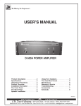
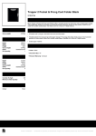
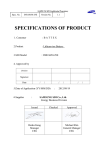
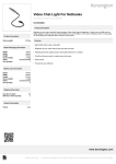
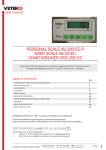
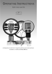
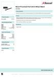
-92000/02/11
No.
21:21:58
TARE
NET
GROSS
TOTAL
----------------------------------------------001 0.000U1 0.034U1 0.034U1 0.034U1
DATE 2000/02/11
TIME 21:26:56
NO.
001
TARE
0.000kg
NET
0.076kg
GROSS
0.076kg
DATE 2000/02/11
TIME 21:27:41
NO.
002
TARE
0.125kg
NET
0.035kg
GROSS
0.160kg
WIDRA - HF L / HF S
SECTION 6 ERROR CODES
ERROR
CODES
- - OL - -
DESCRIPTION
RESOLUTION
Over range
Remove weight from the scale.
Err 1/Err 2
Date and Time not right
Reset again.
Err 4
Zero Setting Error
The scale was outside the normal zero setting
range either when it was turned on or when
the ZERO Key was pressed. Remove weight
from the scale and try again. Use the TARE
Key to set the display to zero value.
Weighing Indicator
User’s Guide
-8“P4 AZ”: Select the auto zero maintenance, Options: 0.5d/1d/2d/4d. “d” means division.
“P5 DEC”: Set the decimal point. Options: 0/0.0/0.00/0.000/0.0000.
“P6 CAP”: Set the capacity.
“P7 INC”: Set division increment. Options: 1/2/5/10/20/50.
“P8 CAL”: Calibration
After finishing all necessary settings above, the indicator is ready for calibration. (Note: If
the scale has settings already done you can directly calibrate it.) Press FUN Key when
displaying “P8 CAL”. Display will show “noLoAd”. Empty the platform by removing the
weight if any. When platform is empty and STABLE indicator is on then press FUN Key to
confirm. Display shows “XXXXXX”. Set it to be the weight of the weigher you want to put
on. Press FUN Key to confirm, and it will show “LoAd”. Put the calibration weigher on the
platform and press FUN Key after the STABLE indicator is on. Indicator will go to weighing
state. The calibration is finished.
“P9 INT”: Initialize the memory to ex-work state.
“P10 RS”: Communication mode.
This option is used for the RS232C serial port mode setup. Options: “RS Cot” is
continuous Data Transmission for using Remote Display or External Display, “RS Prt” is
used for the Serial Printer. “RS Aut” is used for “transmission after every weighing”.
“P11 FL”: Weight adjustment for acceleration of gravity.
Table of Contents
“P12 KB”: When “on”, keyboard is pressed with sound.
“P13 UT”: Unit setting. Lb, U1 or U2 is optional, which could be “ON” or “OFF” through
pressing the FUN Key and TARE Key. When U1/U2 is “ON”, the conversion coefficient
SECTION 1 INTRODUCTIONS………………………………………………………………1
can be set through pressing UNIT Key while self-checking. When U1/U2 is “OFF”, it could
not be set unless entering the P13 UT menu and set it “ON”.
1.1 Introduction……………………………………………………………………………………1
1.2 Specification…………………………………………………………………………………..1
1.3 Installation………………………………………………………………………………..…...1
SECTION 2 KEYS DESCRIPTIONS………………………………………………………2
SECTION 5 RS-232 OUTPUT
Specifications: RS-232 output of weighing data, 1200/2400/4800/9600/19200 bps,1 stop
SECTION 3 OPERATIONS…………………….……………………………………….…..3
bit, 8 data bits, No Parity.
3.1 Power on/off...................................................................................3
Mode 1: Continue output
3.2 Functions and parameters setting...........................................................................3
3.3 Zero the scale...................................................................................3
ST,GS 0.119,kg
ST for stable; US for unstable ; GS for gross weight; NT for net weight ;
0.119 for weighing value; kg for unit (kg, lb); HEX 0d and HEX oa : HEX for hex; 0d for
enter; 0a for next line.
3.4 Tare the scale………………………………………………………………..…….4
3.5 Parts counting (KEY=1)…………………………………………………………4
Mode 2: Automatic output
Automatic output mode is same as continue output. The only difference is:
3.6 Accumulation (KEY=2)…………………………………………………………….5
3. 7 Holding the weight (KEY=3)…………………………………………………. 5
3.8 Pres ett ing tare v alue (KEY=4)………………………………………………. 5
After weighing, when take away the goods display returns to zero, then transfers.
Data Format for normal weighing operations. Examples as follow:
3.9 Animal weighing (KEY=5)…………………………………………………………5
-73. 10 Chec k - we igh ing. . . . . . . . . . . .. . . . . . .. . . . .. . . . .. . . . .. . . . .. . . . . .. . . . .. . . .. . . . . . .. . . . .. . . . ..6
Date setting: Same as time setting.
“F2 SLP”: Sleep function
3.11 Print (KEY=2)...................................................................................6
SLP no: Set to “SLP no” means the indicator will never sleep.
SECTION 4 FUNCTIONS AND PARAMETERS……………………………………..…7
SLP 3:
SECTION 5 RS-232 OUTPUT……………………………………………………………..8
Set the time span 3 minutes for the sleep. This sleep mode has two options: “off
& dot”, which can be selected by pressing FUN Key when displaying “SLP 3” . ”off” means
cutting off the power and “dot” means only a dot at the last digit will be displayed. When
“dot”, weight changing can wake up the indicator.
SLP 5/10/15:
Same as SLP 3.
“F3 KEY”: MOD Key setting
KEY
1
To set the MOD Key for counting, gross / net weight display switch.
KEY
2
To set the MOD Key for accumulation & print.
KEY
3
To set the MOD Key for holding the weight value.
KEY
4
To set the MOD Key for setting tare value in advance.
KEY
5
To set the MOD Key for animal weighing parameters setting.
“F4 CHK”: Check-weighing setting
Options: BEEP 1/2/3.
“F5 INP”: Display the internal counts
Used to check the connection of loadcell and working status of ADC circuit.
Press “TARE” to exit.
“F6 BAT”: Battery and voltage revised
Note: Need a adjustable DC instead of battery inside to move on this function.
1) Enter “F6 BAT”, it displays voltage of the indicator.
2) If need to revise press FUN Key, press ZERO key to exit.
3) Press FUN Key and it displays “1 XXXX”. Now DC power supply is 6V. When stable,
press FUN Key and “2 XXXX” is displayed. Now DC power supply is 7V. When stable,
press FUN Key and revising is finished.
“F7 CAL”: Calibration
“PN”: Press FUN Key to enter “PN”, then press UNIT Key, ZERO Key, TARE Key orderly
as password. Key-press internal can not exceed 2 seconds.
“P1 SP”: Set AD converting speed. Options: 1/2/3/4/5. 1 is the fastest and 5 is the
slowest.
“P2 AUT”: Select the “Power on “ zero maintenance, Options: 0/2/5/10/20/50/100% of
the capacity.
“P3 RAN”: Select the manually zero maintenance, Options: 2/ 4/10/20/50/100% of the
capacity.
SECTION 6 ERROR CODES……………………………………………………………..9
-1-
-6new display.
SECTION 1 INTRODUCTIONS
Press FUN Key to enter or cancel the animal weighing function.
1.1 Introduction
The indicator provides an accurate, fast and versatile series of general purpose weighing
3.10 Check-Weighing
indicator with counting, check-weighing, animal weighing functions.
Check-weighing is a procedure to cause alarm to sound when the weight on the scale
All the keys are sealed color-coded membrane switches and the displays are large LED
meets or exceeds values stored in memory. The memory holds values for a high limit and
display easy to be read.
a low limit.
All units include automatic zero tracking, audible alarm for pre-set weights, automatic tare,
and an accumulation facility that allows the individual weights to be stored and recalled as
Check range:
an accumulated total.
Set hi-limit and low-limit as different values, and hi-limit value is larger than low-limit value.
Check key point:
Set hi-limit and low-limit as same value.
1.2 Specification
Zero range
0mV~8mV
Check mode:
Max input
15mV
Setting the parameter: Select
ADC
Σ-Δ
and sub select “BEEP 1, BEEP 2 or BEEP 3”; Press FUN Key, it will show “XXXXXX”.
External Resolution
1/15000
Interface
RS-232 Output
Stabilisation time
1 second typical
Operating temperature
0°C - 40°C / 32°F - 104°F
”F4 CHK” to enter check mode. Press FUN Key to enter
Then begin to set high-limit value; Press Enter to set low-limit value;
Mode 1: BEEP=1, never beep whether it is eligible or not, but the indicator HI or LO will be
on or off to show the result. When the weight is higher than the high-limit,
indicator HI will be on, while lower than the low-limit indicator LO will be on.
Otherwise indicator HI & LO will be both on.
220~240V AC (110V optional) 50/60Hz
Mode 2: BEEP=2, beep when it is eligible;
built-in rechargeable battery 6V1.3AH.
Mode 3: BEEP=3, beep when it is not eligible.
Display
6 digits 1’LED digital display.
Note: The weight must be greater than 9 scale divisions for the check weighing to operate.
Housing
Stainless steel
To disable the check-weighing function press UNIT Key to set both high and low limit to
Load cell drive voltage
5V/ Max 150mA
zero.
Other function
Real-time clock and units conversion
Load cells
Up to eight 350 ohms cells
Power supply
3.11 Print (KEY=2)
Set “F7 CAL” - “P10 PS”: “RS Prt” is selected for the Serial Printer.
1.3 Installation
When weighing, press MOD Key to print.
The weighing indicator should be sited in a location where the accuracy would not be
degraded.
Avoid extremes of temperature. Do not place it in direct sunlight or near air conditioning
vents.
Avoid unsuitable tables. The tables or floor must be rigid and not vibrate. Do not place
near vibrating machinery.
Avoid unstable power sources. Do not use near large users of electricity such as welding
equipment or large motors.
Keep the weighing indicator clean.
Verify the voltage showing on the label matches the voltage in your area.
SECTION 4 FUNCTIONS AND PARAMETERS
“F1 CLK”: Date and time setting
When “F1 CLK” is showed, press FUN Key. It will display the time.
Time setting:
ZERO Key: shift digit;
MOD Key: cancel and esc;
TARE Key:
FUN Key:
value up;
enter and esc;
Select date setting mode by pressing TARE Key. “YY-MM-DD”, “MM-DD-YY” or
“DD-MM-YY”
-5samples from the container and place the desire parts for counting purpose. Display will
-2To connect the indicator to loadcell, see the diagram below.
show the number of parts (pcs).
Viewing the Unit Weight, Nos. of Counts & Total Weight:
Press FUN Key to cycle through Unit Weight, Nos. of Counts and Total Weight. (Note that
the Unit Weight will show in gram.)
Press MOD Key to return to normal weighing.
3.6 Accumulation (KEY=2)
Accumulate the weight:
When weighing, press FUN Key for accumulation.
Place the products that to be weighed, when the STABLE indicator is on, press MOD Key
and the weight value will be stored in the memory. The display will show nos. of
Layout of PC Board
accumulation. After that it goes to normal weight display. Do other subsequent weighing
by the similar procedure as described above. Note: This Indicator can store 200 Nos. of
accumulation.
SECTION 2 KEY DESCRIPTIONS
View the accumulated total weight:
Empty the scale by removing the weights. Press FUN Key it will display the Nos. of
SOFT POWER ON/OFF Key
weights, and then total weight.
Power on/off the indicator.
Clear the accumulated weight from memory:
Press ZERO Key during display of the nos. of weights and total weight, accumulated
weights are cleared from memory.
ZERO Key
1) When self-checking, Press ZERO Key to enter parameter setting;
3.7 Holding the weight (KEY=3)
Press MOD Key to enter the hold function. After every weighing, the weight value will be
2) Set the zero point for all-subsequent weighing;
3) Move the cursor to change the digit when setting parameters or other functions.
kept on the display. MOD Key can be pressed to cancel hold function.
TARE Key
3.8 Presetting tare value (KEY=4)
1) When self-checking, Press TARE Key to enter fast calibration;
Press MOD Key to preset tare value. While every weighing, the value displayed is the one
2) Tare the scale. Store the current weight in memory as a tare value, subtract the tare
actual weight substrate the preset tare value.
value from the weight and shows the net weight. Entering a value using the keypad will
store that value as the tare value;
3) Cycle through the functions or increase the active digit when setting value for
3.9 Animal weighing (Key=5)
parameters or other functions.
Press MOD Key to set parameters of animal weighing.
1) Stable time “Fil n”. Options: 1/2/3/4/5. 1 is the fastest and 5 is lowest. The longer of
MOD/ ESC Key
stable time, the harder to lock.
1) Enter / Cancel the counting mode from weighing mode when “F3 KEY”=1;
2) Display range “Rang n”. Options: 1/2/3. Option 2 is recommended.
2) Accumulate and print when “F3 KEY”=2;
3) Leaving lock range. If the change of weight exceeds the value, the indicator will get a
3) “Hold” Function keep and cancel when “F3 KEY”=3;
-3-
-4-
4) Enter pre-tare value when “F3 KEY”=4;
measured. Usually this will only be necessary when the platform is empty. When the zero
5) Parameter setting for animal weighing when “F3 KEY”=5;
point is obtained the ZERO indicator is ON.
6) Cancel or quit from the operations.
The scale has an automatic re-zeroing function to account for minor drifting or
accumulation of material on the platform. However you may need to press ZERO Key to
FUN Key
re-zero the scale if small amounts of weight are shown when the platform is empty.
1) Select or enter the function and save the setting values of parameters;
2) View unit weight, counts and total weight when counting mode (“F3 KEY”=1);
3.4 Tare the scale
3) View nos. of accumulated weight and total weight when “F3 KEY”=2;
When a container is applied it needs to tare off and obtains a net weight. Remove all
4) Enter/Cancel animal weighing function when “F3 KEY”=5;
weights from the platform and make the platform empty. Make sure that the ZERO
indicator is on. Place a container on the platform and the container’s weight will be
UNIT Key
displayed. Press TARE Key to tare the scale. The container’s weight will be stored as a
1) When self-checking, press UNIT Key to set unit conversion coefficient.
tare value and the value will be subtracted from the display, leaving a zero value on the
2) Unit conversion when weighing.
display. The TARE indicator will be on to show the indicator is now under tare operation. A
product is placed in the container and it will show only the weight of the added product.
SECTION 3 OPERATIONS
The scale should be tare a second time if another is added to the first one. Again only the
weight added after tare will be displayed.
3.1 Power on/off
Press ON/OFF Key to power on the Indicator and the indicator self-checks, then goes into
the weighing state.
When the container is removed a negative value will be shown. If the scale was tare just
before removing the container this value is the gross weight of the container plus all
products that were removed. The ZERO indicator will also be on because the platform is
back to the same condition it was when the ZERO Key was last pressed.
3.2 Functions and parameters setting
When self-checking, press ZERO Key to enter parameter setting. Then display shows “F1
CLK”. Press TARE Key to move functions cycle. Press FUN Key to enter the desire
function or MOD Key to cancel or quite. See details on Section 4 Functions and
Parameter Sections.
To clear the tare value, empty the platform and press TARE Key again, TARE indicator will
be goes off.
3.5 Parts counting (KEY=1)
When self-checking, press TARE Key to enter “P8 CAL” calibration function.
Tare the weight of any container that is used, leaving the empty container on the scale.
When self-checking, press MOD Key to enter “P13 UT” unit setting.
Place samples on the scale. The number of samples should match the options for parts
When self-checking, press FUN Key to stop self-checking and it goes into the work state.
counting, 10, 20, 50, 100 or 200 pieces.
When self-checking, press UNIT Key to enter unit conversion coefficient setting.
Weighing sample: Press MOD Key to begin the parts counting. The scale shows
"P
10" asking for a sample size of 10 parts. Change the sample size by pressing the TARE
3.3 Zero the scale
Key, the display will cycle through the options: 10/20/50/100/200.
Press ZERO Key to set the zero point from which all other weighing and counting is
Counting: Press FUN Key when the number matches the sample size.
Remove