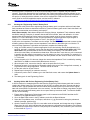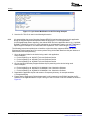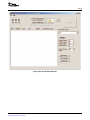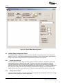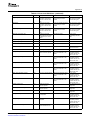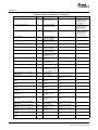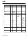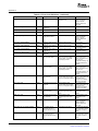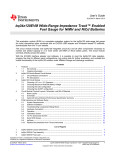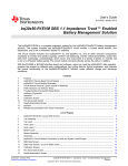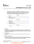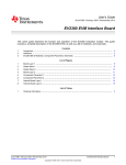
1
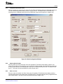
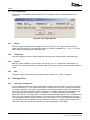
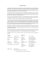
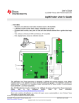
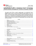
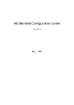
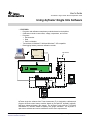
User's Guide SLUA352A – August 2005 – Revised September 2006 Using bqTester Single Site Software Texas Instruments I2C:VOUT Test Fixture SMB I2C EV2300 HDQ FEATURES – Programs and calibrates smart battery modules based on the bq20zxx – Calibrates coulomb counter offset, voltage, temperature, and current – Programs • Serial number • Date • Pack Lot Number – Test software is Windows™ 2000 and Windows™ XP compatible. – Data-logging feature preserves calibration records. USB • 470 Ohm 1% P+ SLP SYS VSS P- 1N 1P 2P 3P 4P 470 Ohm 1% 470 Ohm 1% 470 Ohm 1% Power Supply 2 Power Supply 1 bqTester single site software from Texas Instruments (TI) is designed to calibrate and program electronic smart battery modules based on the bq20z70, bq20z80, bq20z90, and future advanced battery gas gauges. The bqTester works with the TI EV2300 USB-based PC interface board for battery fuel gauge evaluation. The bqTester is open-source software and can be modified to suit the user’s requirements. SLUA352A – August 2005 – Revised September 2006 Submit Documentation Feedback Using bqTester Single Site Software 1 www.ti.com Contents 1 Minimum System Requirements .................................................................. 3 2 Software Installation ................................................................................ 3 3 Interface Connections ............................................................................ 14 4 Testing .............................................................................................. 14 5 Software Change Recommendations .......................................................... 25 Appendix A Error Code Definitions .................................................................. 26 List of Figures 1 2 3 4 5 6 7 8 9 10 11 12 13 14 15 16 17 18 19 20 21 22 23 24 Welcome Screen ................................................................................... 3 Single Site Setup Wizard .......................................................................... 4 Choose Components Box ......................................................................... 5 Choose Start Menu Folder Box ................................................................... 6 Completing Setup Wizard Box .................................................................... 7 Found New Hardware Wizard..................................................................... 8 Alternate Found New Hardware Screen ......................................................... 9 Windows Logo Testing Screen ................................................................... 9 Confirm File Replace Screen .................................................................... 10 Completing the Found New Hardware Wizard Screen ....................................... 10 Found New Hardware Wizard ................................................................... 11 Alternate Found New Hardware Screen ....................................................... 11 Windows Logo Testing Screen .................................................................. 12 Confirm File Replace Screen .................................................................... 12 Completing the Found New Hardware Wizard Screen ....................................... 13 Single Site Tester Interface Connections ...................................................... 14 Cycle Count Modification in GG File Using Notepad ......................................... 16 EV Software Pro Screen ......................................................................... 17 Data Flash Reader Screen ...................................................................... 18 bqTester Main Window ........................................................................... 19 bqTester Main Window Unlocked ............................................................... 20 Global Configuration Window.................................................................... 21 Targets File ........................................................................................ 23 VTI Configuration Box ............................................................................ 24 List of Tables A-1 Error Code Definitions ............................................................................ 26 Impedance Track is a trademark of Texas Instruments. Windows is a trademark of Microsoft Corporation. 2 Using bqTester Single Site Software SLUA352A – August 2005 – Revised September 2006 Submit Documentation Feedback www.ti.com Minimum System Requirements 1 Minimum System Requirements • • • • • • • 2 Computer: PC or compatible Operating system: Windows™ 2000, or Windows™ XP. Operation with Windows™ 98SE may be possible but is untested and unsupported. Minimum video resolution is 640x480; recommended: 800x600 or above 1 available USB port 1 EV2300 USB-based PC interface board for battery fuel gauge evaluation from Texas Instruments 5-MB available hard drive space Visual Basic version 6.0 with Service Pack 5 is required if user wishes to alter program operation. Software Installation The TI bq SingleStationTester Software.exe executable file installs all required software, drivers, and DLL files for proper software operation. To install the software: • Do not connect any EV2300s to the PC before installing the software. If any are connected, disconnect them now. • It is recommended to check for software in the bqTester Tool Folder on the www.ti.com Web site. The Tool Folder is located at: http://focus.ti.com/docs/toolsw/folders/print/bqtester.html • If installing software downloaded from the above Web site, then unzip the downloaded file into a temporary directory and go to Start, Run, and type: C:\Yourdirectory\TI bqSingleStationTester Software.exe and click OK (replace C:\Yourdirectory with the location where the file was unzipped). • . The welcome screen shown in Figure 1 is displayed. Figure 1. Welcome Screen After a few seconds, the Single Site Setup Wizard will appear as shown in Figure 2. SLUA352A – August 2005 – Revised September 2006 Submit Documentation Feedback Using bqTester Single Site Software 3 www.ti.com Software Installation Figure 2. Single Site Setup Wizard Click Next to continue installing the Single Site software. The License Agreement box appears. After carefully reading the License Agreement, click I Agree to continue installation. Note: clicking cancel aborts the installation. After I Agree has been clicked, the Choose Components box appears as shown in Figure 3. 4 Using bqTester Single Site Software SLUA352A – August 2005 – Revised September 2006 Submit Documentation Feedback www.ti.com Software Installation Figure 3. Choose Components Box Notice that Core Components= is selected and grayed out. No other selections can be made. Click Next to proceed. The Choose Start Menu Folder box appears as shown in Figure 4. SLUA352A – August 2005 – Revised September 2006 Submit Documentation Feedback Using bqTester Single Site Software 5 www.ti.com Software Installation Figure 4. Choose Start Menu Folder Box Choose the Start Menu folder where you want the program’s shortcuts to be created. The default is Texas Instruments. After choosing the installation folder, click Install. A box is displayed showing the files being installed, followed by the Completing Setup Wizard as shown in Figure 5. 6 Using bqTester Single Site Software SLUA352A – August 2005 – Revised September 2006 Submit Documentation Feedback www.ti.com Software Installation Figure 5. Completing Setup Wizard Box Click Finish to complete installation. Be sure to check the Show Readme box if additional information is desired 2.1 EV2300 Driver to USB Port Association Two drivers are associated with the EV2300. An instance of the two drivers must be associated with the EV2300 connected to the bqTester PC through any USB port. If an EV2300 is connected to the bqTester PC and the PC detects that it has not had an EV2300 connected to that particular USB port before, then the computer requires the following procedure to associate a copy of the drivers for that USB port. To associate an instance of the EV2300 drivers to any given USB port, connect an EV2300 to the bqTester PC. After a few seconds the Found New Hardware screen appears as seen in Figure 6. Note: if an EV2300 has been installed on the PC previously, the Found New Hardware screen does not appear and installation is complete. SLUA352A – August 2005 – Revised September 2006 Submit Documentation Feedback Using bqTester Single Site Software 7 www.ti.com Software Installation Figure 6. Found New Hardware Wizard Select No, not at this time and click Next. If the first screen that appears does not look like this screen, then it looks like the one shown in Figure 7. 8 Using bqTester Single Site Software SLUA352A – August 2005 – Revised September 2006 Submit Documentation Feedback www.ti.com Software Installation Figure 7. Alternate Found New Hardware Screen Select Install the software automatically (Recommended) and click Next. This wizard is for the first of the two drivers (TI USB Firmware Updater) required for the EV2300. The Windows Logo Testing screen appears as shown in Figure 8. Figure 8. Windows Logo Testing Screen SLUA352A – August 2005 – Revised September 2006 Submit Documentation Feedback Using bqTester Single Site Software 9 www.ti.com Software Installation Click Continue Anyway to proceed with the installation. It is common for the next screen to be the Confirm File Replace screen as shown in Figure 9. Figure 9. Confirm File Replace Screen Click No to continue. If this screen does not appear, then the next screen is the Completing the Found New Hardware Wizard screen as seen in Figure 10. Figure 10. Completing the Found New Hardware Wizard Screen The TI USB Firmware Update driver is now installed for the EV2300. Click Finish to exit the driver install wizard. After a few seconds, another Found New Hardware screen appears to start the installation of the final driver for the EV2300 as shown in Figure 11. 10 Using bqTester Single Site Software SLUA352A – August 2005 – Revised September 2006 Submit Documentation Feedback www.ti.com Software Installation Figure 11. Found New Hardware Wizard Select No, not at this time and click Next. If the screen that appears does not look like this, then it looks like the one shown in Figure 12. Figure 12. Alternate Found New Hardware Screen Select Install the software automatically (Recommended) and click Next. This wizard is for the second of the two drivers (TI USB bq80XX Driver) required for the EV2300. The Windows Logo Testing screen appears as shown in Figure 13. SLUA352A – August 2005 – Revised September 2006 Submit Documentation Feedback Using bqTester Single Site Software 11 www.ti.com Software Installation Figure 13. Windows Logo Testing Screen Click Continue Anyway to proceed with installation. It is common for the next screen to be the Confirm File Replace screen as shown in Figure 14. Figure 14. Confirm File Replace Screen Click No to continue. If this screen does not appear, then the next screen is the Completing the Found New Hardware Wizard screen as seen in Figure 15. 12 Using bqTester Single Site Software SLUA352A – August 2005 – Revised September 2006 Submit Documentation Feedback www.ti.com Software Installation Figure 15. Completing the Found New Hardware Wizard Screen The TI bq80xx Driver is now installed for the EV2300. Click Finish to exit the driver install wizard. At this point, the installation of the EV2300 is complete. Source code in Visual Basic 6.0 format is available if the user wishes to modify the behavior of the bqTester. Contact TI for access to the source code. SLUA352A – August 2005 – Revised September 2006 Submit Documentation Feedback Using bqTester Single Site Software 13 www.ti.com Interface Connections 3 Interface Connections HDQ EV2300 Texas Instruments Test Fixture I2C:VOUT SMB I2C USB The bqTester software requires that the TI EV2300 USB-based PC interface board for battery fuel gauge evaluation interface be installed and running properly. The smart battery module should be connected to the EV2300 board and external power supplies as shown in Figure 16. 470 Ohm 1% 470 Ohm 1% P+ SLP SYS VSS P- 1N 1P 2P 3P 4P 470 Ohm 1% 470 Ohm 1% Power Supply 2 Power Supply 1 Figure 16. Single Site Tester Interface Connections Note: Do not use actual battery cells with this software. Cells should be simulated with resistors as shown in Figure 16. The relays used to validate this procedure are 10-A, 250-Vac relays with a 5-Vdc coil. Any brand can be used but the ones used during this test were Omron model G6RN-1. The diodes used were 1N4148. Set the power supply 1 Vdc to 3 Vdc and limit current to 2 A dc. Set power supply 2 to the voltage corresponding to the number of cells being simulated (e.g., 10.8 Vdc for 3 cells or 14.4 Vdc for 4 cells). A calibrated temperature probe also is needed to measure the actual temperature. 4 Testing 4.1 Creating the Golden Image File (mandatory procedure) After engineering development has been completed, a golden data flash image file must be made from an Engineering Perfect module. This Golden Image file is used as a default to program the Static Data Flash constants in all the bq20zxx-based smart battery modules using bqTester during production. It is important 14 Using bqTester Single Site Software SLUA352A – August 2005 – Revised September 2006 Submit Documentation Feedback www.ti.com Testing that this process is completed. If it is not, then the Impedance Track™ algorithm may not function correctly. This section assumes the user's familiarity with Texas Instruments evaluation software for the bq20zxx modules because the user was most likely used it during the engineering development phase of this project. If unfamiliar with the software, then see the bq20z80-001 EVM tool folder that includes a user's guide for the EVM, application reports, and the latest EV software: http://focus.ti.com/docs/toolsw/folders/print/bq20z80evm-001.html 4.1.1 Creating the "Engineering Perfect" Battery Pack It is assumed at this point that an engineering prototype battery pack is complete and that all static data flash constants have been reviewed and verified for a particular battery pack model. Static data flash is all data flash constants that are not battery pack specific. Static Data examples: Static data examples are Charging Voltage, Impedance Track resistance tables, and QMAX settings. Examples of nonstatic data include serial number, date, and calibration. It is also assumed that this Engineering Perfect battery pack was created using the correct chemistry support SENC file. For more information on this, see the multichemistry support application report Support of Multiple Li-Ion Chemistries With Impedance Track™ Gas Gauges (SLUA372). At this point, the Impedance Track data must be verified. This data must be updated and accurate so that all battery packs produced have accurate Impedance Track tables in data flash right out of the box. To ensure that the Impedance Track tables are optimized, complete the following steps: 1. Using an EV2300 and the EV software appropriate for the device being used in this application (e.g., bq20z70, bq20z80, or bq20z90), ensure that the data flash locations Qmax Cell 0–Qmax Cell 3, and Qmax Pack have good estimates in them for the battery pack capacity. This information can be derived from the battery cell manufacturer data sheet. Also note that if more than one cell is connected in parallel, then the capacity increments by one cell capacity for every cell in parallel. For example, if a single-cell data-sheet capacity is 2400 mAh, and three parallel cells are used, set each value to 2400 x 3 = 7200 mAh. 2. Charge the pack to full. If it does not charge then ensure that Impedance Track is enabled by sending data 0x0021 to SMBus command 0x00 (Manufacturer Access). 3. When the pack is full, remove the charger, and let the pack relax for 2 hours. 4. Discharge the pack to minimal device acceptable voltage (also set as Term Voltage flash constant), at a typical rate for the target application. The exact rate is not critical. 5. Let the pack relax for at least 5 hours. 6. Repeat steps 2 through 5 for maximum accuracy. 7. Connect the pack to the EV software, go to the data flash screen, and ensure that Update Status is 0x06. 8. The battery pack is now Engineering Perfect. 4.1.2 Creating Golden GG file from Engineering Perfect Battery Pack A GG file needs to be created with all the data from the Engineering Perfect battery pack that is used in creating the Golden Image File. The purpose of this GG file is to ensure that all the nonreserved data is saved so that it can be installed back into the module after the battery pack is put back into the original state with a new SENC file (discussed in the next section). You also want to change usage data to original values so th at all production battery packs do not report that they have been used. To make this Golden GG file, do the following: 1. Ensure that the Engineering Perfect battery pack is still connected to the EV2300 and that the EV software for the applicable device is open. 2. Go to the Data Flash screen in the EV software, and click the Read All button. 3. Select the File pulldown menu, click Export, and chose a (*.gg) file name for saving the prelearned defaults (example: optimized.gg). 4. Open the saved GG file from step 3 in a text editor such as Notepad, and change the value of Update Status from 06 to 02, which indicates that the parameters are learned but the Impedance Track feature is disabled (as should be the case for a new pack prior to calibration). Also, reset the Cycle Count field to 0 as shown in Figure 17. SLUA352A – August 2005 – Revised September 2006 Submit Documentation Feedback Using bqTester Single Site Software 15 www.ti.com Testing Figure 17. Cycle Count Modification in GG File Using Notepad 5. Save the file. This file is used in the following discussion. 4.1.3 It is assumed that the proper Chemistry Support SENC file has been determined for this application during the Engineering and Development Phase of this project. For most applications (LiCoO2/graphitized carbon chemistry), the default SENC file for the applicable device (e.g., bq20z80, bq20z90, or bq20z70) is used. For more information on multichemistry support. see the TI application report Support of Multiple Li-Ion Chemistries With Impedance Track™ Gas Gauges (SLUA372). The following instructions explain how to install the original chemistry supported SENC file into the Engineering Perfect battery pack. Do not worry about losing all the static data from this pack because it was stored as discussed previously. 1. Go to the product folder for the device being used in this application. Some Examples: a. For the bq20z70 go to: bq20z70 Tools and Software Section b. For the bq20z80 go to: bq20z80 Tools and Software Section c. For the bq20z90 go to: bq20z90 Tools and Software Section 2. Click on the Multi-Chemistry Support Software zip file pertaining to the device being used: Some Examples: a. For the bq20z70 go to: bq20z70-V101 Multiple Li-Ion Chemistries Software b. For the bq20z80 go to: bq20z80-V102 Multiple Li-Ion Chemistries Software c. For the bq20z90 go to: bq20z90-V102 Multiple Li-Ion Chemistries Software 3. Download the applicable zip file and extract to a temporary directory. An example would be C:\Temp\sluc058.zip 4. Ensure that the Engineering Perfect battery pack is still connected to the EV2300 and that the EV software for the applicable device is open. Then go to the Pro screen in the EV software as shown in Figure 18. 16 Using bqTester Single Site Software SLUA352A – August 2005 – Revised September 2006 Submit Documentation Feedback www.ti.com Testing Used Command 0x08 to put bq20zXX back into Gas Gauge Mode from ROM mode Write 0x0F00 to SMBus command 0x00 to put bq20zXX into ROM mode for SENC file creation Load the SENC file Figure 18. EV Software Pro Screen 5. Ensure that Write SMB Word frame has the SMBus Command set to 0x00 and the SMBus Word set to 0x0F00. If they are not, then change them. 6. Then click Write. This puts the bq20zxx module into ROM mode to prepare for writing the SENC file created in the previously discussed section. 7. Write the SENC file to the Engineering Perfect pack by clicking the browse ( ) button in the Srec programming frame. 8. In the file manager that pops up, locate and select the previously saved SENC file created in the previously discussed section. 9. Then click the Program button. The software will indicate when finished. 10. After writing is finished, ensure that the SMB Command is 0x08 in the Send SMB Command frame. If it is not, then change it to 0x08. 11. Click the Send button. This puts the bq20zxx back into Gas Gauge mode. Your factory default SENC file is now loaded. 4.1.4 Creating the Golden Image File The final step in this process is creating the Golden Image file. This file includes all the static data in the data flash that is constant from one smart battery module to the next. It also has all the reserved data and usage data set to default states to ensure that all production packs start out in a new state. This process is mandatory for new designs. Without this process the Impedance Track Algorithm may not function properly. Follow these steps to create this file: 1. Ensure that the Engineering Perfect battery pack is still connected to the EV2300 and that the EV software for the applicable device is open. Then go to the Data Flash screen, open the File pulldown menu, and select Import. SLUA352A – August 2005 – Revised September 2006 Submit Documentation Feedback Using bqTester Single Site Software 17 www.ti.com Testing 2. In the file manager that pops up, locate and select the Golden GG file created in the preceding section and click the Write All button. 3. The Engineering Perfect battery pack now has all Golden data in it. The next step is to retrieve that data into a Golden image file. 4. Run the Data Flash reading software in the bqTester suite by double-clicking the TesterDFReader icon. The Data Flash reader screen appears as shown in Figure 19. Figure 19. Data Flash Reader Screen 5. Select the device type being read from the Device pulldown menu. 6. Type in a complete path and file name with a .rom extension in the dialog box or click the browse button ( ). This is the file that contains the Golden Image. 7. Click the Read Data Flash Image button. This causes the software to read the data flash information from the bq20zxx-based smart battery module and store it in this file. This .rom file is now the golden data flash image file which is used to program all other similar bq20zxx-based smart battery modules in the production process. 4.1.5 Running the bqTester Software Follow all instructions in Section 1 to install the software. After installation, double-click the bqTester icon on the PC desktop or launch the bqTester program from the Start menu. The single site tester main window appears as shown in Figure 20. Press the Unlock Configuration button. The default password is bq20z80. After entering the default password, two new buttons appear on the single site tester screen as shown in Figure 21. They are Global Configuration and VTI configuration. 18 Using bqTester Single Site Software SLUA352A – August 2005 – Revised September 2006 Submit Documentation Feedback www.ti.com Testing Figure 20. bqTester Main Window SLUA352A – August 2005 – Revised September 2006 Submit Documentation Feedback Using bqTester Single Site Software 19 www.ti.com Testing Figure 21. bqTester Main Window Unlocked 4.2 Setting Global Configuration Values Pressing the Global Configuration button causes the bqTester Configuration window to be displayed as shown in Figure 22. In the global configuration screen, all numeric values are specified in signed decimal except for the serial number field which is unsigned with a maximum value of 65535. 4.2.1 Current Sense Resistor This box contains two values. Enter the value of the sense resistor used in the Impedance Track-based smart battery pack in the Sense Resistor field. This value is entered in units of milliohms. Enter the desired acceptable percent error that the sense resistor can differ from the value listed in the Sense Resistor field in the % Error field. Note that the default value for this field is 25%. This test is intended only as a rough test to ensure that the sense resistor is mounted and not shorted; it is not intended to be a highly accurate test of the sense resistor value. This value must be specified as a positive integer value. 4.2.2 Voltage Reference/FSV This box contains two values. The tester calibrates the voltage gain by manipulating the Full Scale Voltage Reference. Do not change the values in these fields. 20 Using bqTester Single Site Software SLUA352A – August 2005 – Revised September 2006 Submit Documentation Feedback www.ti.com Testing 4.2.3 Temperature Maximum Offset This box contains one value and is in units of 0.1°C. Enter the maximum amount of offset that can be put into the module being tested, either positive or negative from 0. The default value of this field is 20, meaning that the calibrated offset entered in the data flash cannot exceed positive or negative 2°C. Figure 22. Global Configuration Window 4.2.4 Starting Serial Number Enter the value for the serial number of the first Impedance Track-based smart battery module to be tested. This number is incremented by one as each new module is tested. If the Skip On Error check box is checked, the number is not incremented in the case of a module that fails the test. The default for this box is 1. This value must be specified as a positive integer value 4.2.5 Pack Lot Code Enter the value for the Pack Lot Code of the group of Impedance Track-based smart battery modules currently being tested. This number does not change until it is changed manually and is programmed into each module tested. This value must be specified as a positive integer value. SLUA352A – August 2005 – Revised September 2006 Submit Documentation Feedback Using bqTester Single Site Software 21 www.ti.com Testing 4.2.6 Date Enter the value for the desired date to be programmed into each Impedance Track-based smart battery module. If the Use Current Date check box is checked, the system date from the computer running the bqTester software is used. 4.2.7 Log File Name Enter the complete path and file name to be used for the log file. This file contains all relevant test data for each Impedance Track-based smart battery module tested. If the Clear Log button is pressed, the log file contents are deleted. 4.2.8 CC Offset Calibration This is the coulomb counter offset. No user-definable values are in this box. Select this calibration by placing a check in its selection box, or deselect it by removing the check. The default is checked. Note that if this test is disabled, the values from the gold data flash file are used and not the values currently in the part. 4.2.9 Temperature Calibration This box shows the currently measured temperature and provides a box for the user to enter the actual temperature as measured by a calibrated meter. If the ambient air temperature changes, this value needs to be updated. This box also offers three different temperature probe selections. The proper selections should be made depending on the application. Temperature calibration can be selected by placing a check in its selection box or deselected by removing the check. The default is checked. Note that if this test is disabled, the values from the gold data flash file are used and not the values currently in the part. 4.2.10 Voltage Calibration This box shows the currently measured voltage and provides a box for the user to enter the actual voltage being supplied to the part as measured by a calibrated meter. It also has a box for the user to enter the number of series cells being simulated. The default number of cells is 4. It also has a FET Control selection box. Select Off (Batt), and supply voltage to the simulation resistors as shown in Figure 16 (this configuration is the default). Never select On (Pack); it is only included for possible future use. To select voltage calibration, place a check in its selection box, or deselect it by removing the check. The default is checked. Note that if this test is disabled, the values from the gold data flash file are used and not the values currently in the part. 4.2.11 Pack Current Calibration This box shows the currently measured current and provides a box for the user to enter the actual current being supplied to the part as measured by a calibrated meter. It also has a FET Control selection box. Always select On (External Load) and supply current to the Pack– and 1N (Batt–) inputs of the bq20zxx-based smart battery pack as shown in Figure 16 (this configuration is the default). Never select Off (Bypassed); it is only included for possible future use. To select Pack Current calibration, place a check in its selection box, or deselect it by removing the check. The default is checked. Note that if this test is disabled, the values from the gold data flash file are used and not the values currently in the part. 4.2.12 Device and Version The correct Device and Version must be selected using the select ( ) button. Once the select button is pressed, select the proper device and firmware version of the modules to be tested form the dialog box that appears. If the device or version desired is not available, check the Texas Instruments Web site for an updated version of the bqTester software in the bqTester tool folder: http://focus.ti.com/docs/toolsw/folders/print/bqtester.html 22 Using bqTester Single Site Software SLUA352A – August 2005 – Revised September 2006 Submit Documentation Feedback www.ti.com Testing Advanced Information: For special/custom parts, it is possible that the part can be added to the file that holds all allowed parts compatible with bqTester. Using this option is sometimes tricky. It is recommended that TI be contacted before using this option to ensure that the bqTester has been tested with the requested device. The file to be edited is called Targets and is located in the directory that bqTester was installed. This file is shown in Figure 23. Figure 23. Targets File 4.2.13 Data Flash Image File Input the location of the data flash Golden file that will be stored in all parts that will be tested when running the bqTester.exe program. Clicking the browse ( ) button gives the option to browse for the Golden image file. If the Update Data Flash Image check box is not checked, then no data flash image will be installed in any parts. It is always recommended that an Image file be used. 4.2.14 Advanced Calibration Board Facilities This frame contains two check boxes. These check boxes are not currently supported for single site testing. They are for use with the HPA169 calibration board when that functionality is added. Both should remain unchecked when using the single site tester software. 4.2.15 Seal Pack on Successful Completion If checked, then the module is sealed on completion of the test. 4.2.16 Save Clicking the Save button causes the current configuration settings to be saved. SLUA352A – August 2005 – Revised September 2006 Submit Documentation Feedback Using bqTester Single Site Software 23 www.ti.com Testing 4.3 VTI Configuration Clicking the VTI Configuration button causes the VTI configuration box to be displayed as shown in Figure 24. Figure 24. VTI Configuration Box 4.3.1 Voltage Enter the voltage supplied by Power Supply 2 as seen in Figure 16. This voltage must be extremely stable. Set the voltage at 3.6 volts times the number of cells being simulated (e.g., 4 x 3.6 = 14.4 v for 4 cells). Measure this voltage with a calibrated meter. 4.3.2 Temperature Enter the temperature near the module under test which has been measured with a calibrated meter. 4.3.3 Current Enter the current supplied by Power Supply 1 as seen in Figure 16. A reasonable current setting is 2 amperes. This current value must be extremely stable. This voltage should be measured with a calibrated meter. 4.3.4 Save Pressing the Save button causes the currently recorded values for V, T, and I to be saved. 4.4 4.4.1 Running the Test Locking the Configuration The test cannot be started until the Lock Configuration button has been clicked. First, check or uncheck the box called Allow V, T, and I update while locked. If selected, the user is able to change actual values for voltage, temperature, and current even though the configuration has been locked. If not selected, the user is unable to alter these values without unlocking the configuration. Note that the configuration must be currently unlocked to select this option. Once Allow V, T, I= while locked has been selected or deselected, click on Lock Configuration. This causes a password dialog to appear. Enter a password, and record it in a safe location for future reference. If you do not wish to enter the password every time the Lock Configuration button is pressed, check the box called Quick Lock. This causes555 the configuration to be locked with the current password. Notice that the Lock Status icon changes from an open lock to a closed lock. Also notice that the Start button is now active and testing can now begin. 24 Using bqTester Single Site Software SLUA352A – August 2005 – Revised September 2006 Submit Documentation Feedback www.ti.com Software Change Recommendations 4.4.2 Starting the Test Click on the Start button to run the test. The software displays a busy indication and then indicates Pass or Fail. The software also displays information about each bq20zxx-based smart battery module tested and its Pass or Fail status. This same information is also recorded in a log file. The log file can be specified by pressing the Log Instead To… button. If a module fails, an error code is displayed and logged. Appendix A defines the error codes for the bqTester software. The information on the screen can be cleared by pressing the Clear Screen button. The statistical information can be cleared by pressing the Clear Statistics button. 5 Software Change Recommendations 1. Add new files when new functionality is added. Do not edit existing files. 2. Edit modSerial.bas to change the way serial numbers are generated. 3. Examples of how to use existing functions to read/write gas gauge constants can be found in the modGGDF.bas file. It is recommended that end-users use these functions for data flash access instead of writing their own. SLUA352A – August 2005 – Revised September 2006 Submit Documentation Feedback Using bqTester Single Site Software 25 www.ti.com Appendix A Appendix A Error Code Definitions Table A-1. Error Code Definitions 26 Error Code Error # Description NO_ERROR 0 Successful (No errors) LOST_SYNC 1 EV2300 lost synchronization EV2300 has outdated firmware or drivers are outdated. Contact TI to get EV2300 with latest firmware. Ensure latest drivers for EV2300 installed. NO_USB 2 USB Connection Missing No EV2300 is connected. Close program, reboot, and connect EV2300 first. BAD_PEC 3 Bad PEC on SMBus Possible Bad hardware. Replace EV2300 / target board WRONG_NUM_BYTES 5 Unexpected number of bytes sent/received Unexpected hardware behavior. May need assistance from TI T2H_UNKNOWN 6 SMBus communication terminated unexpectedly / timed out or the bus was busy. Wrong kind of target connected or target timing is off Trim oscillator make sure that the target mode accepts the SMB command being sent INCORRECT_PARAM 7 Invalid parameter type Incorrect parameter in call to passed to function – function. Software Bug or especially Variant argument. overflow Contact TI TIMEOUT_ERROR 8 USB Timeout No response on USB EV2300 or driver problems or software is not supposed to wait for a response. INVALID_DATA 9 AssemblePacket could not build a valid packet Bad data / bad packet. Software found problem with data Possible version incompatibility between BqTester and Module under test. ERR_UNSOLICITED_PKT 10 Found an unsolicited non-error packet when looking for error packets Unexpected packet received. The packet may be a response from a previous transaction that failed or that did not check the response. Make corrections to software COMPARE_DIFFERENT 11 Comparison failed and data read is different from srec Flash comparison results in mismatch. Possible Flash failure or SMBus failure. Module under test Flash failure BQ80XRW_OCX_INTERNAL_ERROR 12 Problems with pointers being NULL etc. Possible software bug or overflow. Contact TI USER_CANCELLED_OPERATION 34 User clicked on cancel button on progress bar dialog DF_CHECKSUM_MISMATCH 51 Data Flash checksum mismatch Flash comparison results in mismatch. Possible Flash failure or SMBus failure. Module under test Flash failure IF_CHECKSUM_MISMATCH 52 Instruction Flash checksum mismatch Flash comparison results in mismatch. Possible Flash failure or SMBus failure. Module under test Flash failure OPERATION_UNSUPPORTED 53 Unsupported type Software problem Check that Module under test and bqTester versions are compatible. Then contact TI ERR_TOO_MANY_QUERIES 81 Not used ERR_BAD_QUERY_ID 82 Not used BAD_CRC 83 Packet was corrupted during USB communication ERR_TOO_MANY_RESPONSES 84 Not used ERR_NO_QUERIES_TO_DELETE 85 Not used ERR_QUERY_UNAVAILABLE 86 Not used ERR_NO_RESPONSES_TO_DELETE 87 Not used ERR_RESPONSE_UNAVAILABLE 88 Not used ERR_TMMT_NO_RESPONSE 90 Not used Error Code Definitions Most Probable Cause Possible Action Too much noise or bad connection SLUA352A – August 2005 – Revised September 2006 Submit Documentation Feedback www.ti.com Appendix A Table A-1. Error Code Definitions (continued) Error Code Error # Description Most Probable Cause Possible Action T2H_ERR_TIMEOUT 92 SMBus communication terminated unexpectedly / timed out or the bus was busy. Wrong kind of target connected or target timing is off Trim oscillator make sure that the target mode accepts the SMB command being sent BUS_BUSY 94 SMBus communication terminated unexpectedly / timed out or the bus was busy. Wrong kind of target connected or target timing is off Trim oscillator make sure that the target mode accepts the SMB command being sent T2H_ERR_BAD_SIZE 95 SMBus communication terminated unexpectedly / timed out or the bus was busy. Wrong kind of target connected or target timing is off Trim oscillator make sure that the target mode accepts the SMB command being sent ERR_BAD_PAYLOAD_LEN 97 Packet was corrupted during USB communication or software sent in a bad packet Bad USB connection Check Version Compatibility and USB cable ERR_TMMT_LIST_FULL 98 Not used ERR_TMMT_BAD_SELECTION 99 Not used UNKNOWN 100 Unexpected/unknown error UNEXPECTED_ERROR 110 Should not happen OUT_OF_MEMORY 111 Not enough memory on PC SREC_OPEN_FAIL 221 Srec specified does not exist or cannot be opened SREC targets a different device than the one detected on the SMBus Ensure version compatibility between bqTester software and Module under Test. SREC_BAD_START_RECORD 222 Srec not in expected format SREC targets a different device than the one detected on the SMBus Ensure version compatibility between bqTester software and Module under Test. SREC_UNKNOWN_TYPE 223 Srec not in expected format SREC targets a different device than the one detected on the SMBus Ensure version compatibility between bqTester software and Module under Test. SREC_BAD_CHECKSUM 224 Srec not in expected format SREC targets a different device than the one detected on the SMBus Ensure version compatibility between bqTester software and Module under Test. SREC_BAD_RECORD_COUNT 225 Srec not in expected format SREC targets a different device than the one detected on the SMBus Ensure version compatibility between bqTester software and Module under Test. SREC_DEV_MISMATCH 226 SREC targets a different device than the one detected on the SMBus Ensure version compatibility between bqTester software and Module under Test. CONFIG_OPEN_FAIL 227 Config file not found / cannot be opened Redo StationSetup.exe configuration CONFIG_UNEXPECTED_EOF 228 Config file not found / cannot be opened Redo StationSetup.exe configuration CONFIG_BAD_FORMAT 229 Config file format incorrect Redo StationSetup.exe configuration PCFG_DEVVER_MISMATCH 231 Config file device version not compatible Ensure version compatibility between bqTester software and Module under Test. PCFG_DEV_MISMATCH 232 Config file device not compatible Ensure version compatibility between bqTester software and Module under Test. PCFG_SRECDEVVER_MISMATCH 233 Srec not compatible with current hardware device Ensure version compatibility between bqTester software and Module under Test. SLUA352A – August 2005 – Revised September 2006 Submit Documentation Feedback Outdated software Contact TI Unexpected error Hardware not expected to respond to this error Install more memory Error Code Definitions 27 www.ti.com Appendix A Table A-1. Error Code Definitions (continued) 28 Error Code Error # Description PCFG_SRECDEV_MISMATCH 234 Srec not compatible with current hardware device Most Probable Cause Ensure version compatibility between bqTester software and Module under Test. BCFG_DEVVER_MISMATCH 235 Srec not compatible with current hardware device Ensure version compatibility between bqTester software and Module under Test. BCFG_DEV_MISMATCH 236 Srec not compatible with current hardware device Ensure version compatibility between bqTester software and Module under Test. SMBC_LOCKED 260 Unused but reserved for backward compatibility 516 Unused but reserved for backward compatibility T2H_NACK 772 No response from target SMBD_LOW 1028 Unused but reserved for backward compatibility SMB_LOCKED 1284 Unused but reserved for backward compatibility ERR_NOTHINGTODO 5001 Calling the function with specified values resulted in nothing being done ERR_VOLTAGE_LESSTHANZERO 5002 Specified Voltage must be greater than 0 ERR_TEMPERATURE_LESSTHANZERO 5003 Specified temperature must be greater than 0 ERR_CURRENT_EQUALSZERO 5004 Specified current cannot be 0 ERR_NOT_IN_CAL_MODE 5010 Gas gauge was not in Calibration mode/ could not be put in calibration mode ERR_CALIBRATION_IN_FIRMWARE_ FLASHWRITE 5020 Error writing flash in calibration mode Target not connected/not powered ERR_CALIBRATION_IN_FIRMWARE_AFE 5021 Error in AFE calibration Value too large (Overflow) in firmware ERR_CALIBRATION_IN_FIRMWARE_ PACKV 5022 Error in Pack voltage calibration Value too large (Overflow) in firmware ERR_CALIBRATION_IN_FIRMWARE_ PACKG 5023 Error in Pack gain calibration Value too large (Overflow) in firmware ERR_CALIBRATION_IN_FIRMWARE_ VGAIN 5024 Error in Voltage gain calibration Value too large (Overflow) in firmware ERR_CALIBRATION_IN_FIRMWARE_ CCIGAIN 5025 Error in Current gain calibration Value too large (Overflow) in firmware ERR_CALIBRATION_IN_FIRMWARE_ TMPOFFEXT1 5026 Error in external temperature 1 offset calibration Value too large (Overflow) in firmware ERR_CALIBRATION_IN_FIRMWARE_ TMPOFFEXT2 5027 Error in external temperature 2 offset calibration Value too large (Overflow) in firmware ERR_CALIBRATION_IN_FIRMWARE_ TMPOFFINT 5028 Error in internal temperature Value too large (Overflow) in offset calibration firmware ERR_CALIBRATION_IN_FIRMWARE_ ADCOFF 5029 Error in ADC offset calibration Value too large (Overflow) in firmware ERR_CALIBRATION_IN_FIRMWARE_ BRDOFF 5030 Error in Board offset calibration Value too large (Overflow) in firmware ERR_CALIBRATION_IN_FIRMWARE_ CCIOFF 5031 Error in CC offset calibration Value too large (Overflow) in firmware ERR_CALIBRATION_IN_FIRMWARE_ RSVD0 5032 Reserved for future use Error Code Definitions Possible Action Connect target and check is correct power is applied SLUA352A – August 2005 – Revised September 2006 Submit Documentation Feedback www.ti.com Appendix A Table A-1. Error Code Definitions (continued) Error Code Error # Description ERR_CALIBRATION_IN_FIRMWARE_ RSVD1 5033 Reserved for future use ERR_CALIBRATION_IN_FIRMWARE_ RSVD2 5034 Reserved for future use ERR_CALIBRATION_IN_FIRMWARE_ RSVD3 5035 Reserved for future use ERR_CALIBRATION_IN_FIRMWARE_ RSVD4 5036 Reserved for future use ERR_CALIBRATION_IN_FIRMWARE_ RSVD5 5037 Reserved for future use ERR_CALIBRATION_IN_FIRMWARE_ RSVD6 5038 Reserved for future use ERR_CALIBRATION_IN_FIRMWARE_ UNDEFINED 5039 Unknown error code returned by hardware ERR_DF_RD_REQ_B4_WR 5041 Data flash cannot be written before reading the remaining values in a given class ERR_INVALID_DATA_ENTERED 5042 Invalid data entered on screen ERR_USB_ACQUIRE 5043 EV2300 is locked by another thread NVALID_FILENAME 65537 DEVICE_VERSION_MISMATCH 65538 Incompatible device/version RETURN_TO_ROM_FAILED 65539 Gas gauge could not be put in Rom mode Hardware incompatibility Check Connections. Verify version compatibility between bqTester software and Module under Test. RUNGG_FAILED 65541 Gas gauge could not exit ROM mode Hardware incompatibility Check Connections. Verify version compatibility between bqTester software and Module under Test. WRITEFLASH_GG_FAILED 65542 Writing to flash failed Data Flash Failure Module Repair CALIBRATE_FAILED 65543 Calibration failed Module hardware failure or Configuration failure Module Repair or Check Testing Configuration Settings POST_CAL_CHECKS_FAILED 65544 Post calibration checks failed Module hardware failure or Configuration failure Module Repair or Check Testing Configuration Settings WRITESERIAL_FAILED 65545 Write serial number failed Data Flash Failure Module Repair/Retry Test ERR_UNEXPECTED 65552 Unexpected value/response Software does not know how to handle this ERR_FILE 65553 Error opening/processing File Wrong File location settings. Check all File location settings in bqTester Software ERR_NOT_IN_ROM 65554 GG not in ROM mode when expected – communication failure? Gas gauge could not be put in ROM Check Connections. Verify version compatibility between bqTester software and Module under Test. SLUA352A – August 2005 – Revised September 2006 Submit Documentation Feedback Most Probable Cause Possible Action Software is obsolete Attempting to do multiple transactions possibly from different windows in background at the same time. Could also be a software problem. Stop scanning in SBS. Check File Name for Rom File and Log File Check Connections. Verify version compatibility between bqTester software and Module under Test. Error Code Definitions 29 www.ti.com Appendix A Table A-1. Error Code Definitions (continued) 30 Error Code Error # Description Most Probable Cause Possible Action ERR_ENTER_CALMODE 65555 Cannot put GG in Cal mode Gas gauge could not be put in Calibration mode Check Connections. Verify version compatibility between bqTester software and Module under Test. ERR_CUSTOM_FUNC 65556 User defined function returned error BAD_FILE_FORMAT 65557 Header bad or format bad Bad image file format ERR_WRITE_MFG_DATA 65558 Failed to write manufacturer data Data Flash Failure Module Repair/Retry Test ERR_READ_DEV_VER 65559 Communication error reading device version Hardware incompatibility Check Connections. Verify version compatibility between bqTester software and Module under Test. CAL_VOLT_LESSTHANZERO 65600 Calibration voltage must be greater than 0 On screen values incorrect Verify VTI and Configuration Settings CAL_TEMP_LESSTHANZERO 65601 Calibration current must be greater than 0 On screen values incorrect Verify VTI and Configuration Settings CAL_CURR_LESSTHANZERO 65602 Calibration current must be greater than 0 On screen values incorrect Verify VTI and Configuration Settings WRITEFLASH_ROM_FAILED 65560 Failed to write flash while in ROM mode SENSE_RES_CAL_HIGH 65570 Sense resistor value too high in post cal checks Sense Resistor Hardware Failure, Connection Problem, Setting Problem, or HPA169 Power Supply Problem Verify Sense Resistor Value, check current supply connections, and verify VTI and Configuration Settings. Try increasing tolerances if possible SENSE_RES_CAL_LOW 65571 Sense resistor value too low Sense Resistor Hardware in post cal checks Failure, Connection Problem, Setting Problem, or HPA169 Power Supply Problem Verify Sense Resistor Value, check current supply connections, and verify VTI and Configuration Settings. Try increasing tolerances if possible VOLT_CAL_HIGH 65580 voltage value too high in post cal checks Module hardware failure, HPA169 Voltage power supply problem or Configuration failure Verify Voltage circuit, voltage power supply, VTI, and Configuration Settings. Try increasing tolerances if possible VOLT_CAL_LOW 65581 voltage value too low in post Module hardware failure, cal checks HPA169 Voltage power supply problem or Configuration failure Verify Voltage circuit, voltage power supply, VTI, and Configuration Settings. Try increasing tolerances if possible TEMP_CAL_HIGH 65590 temperature value too high in post cal checks Module hardware failure, HPA169 Temperature sensor Failure Verify VTI settings, and Temperature sensor location TEMP_CAL_LOW 65591 temperature value too low in Module hardware failure, post cal checks HPA169 Temperature sensor Failure Verify VTI settings, and Temperature sensor location SEAL_CMD_FAILED 65610 Seal command failed Communication Failure Check Connections. Verify version compatibility between bqTester software and Module under Test. ERR_READ_CB_INT_TEMP_SENSOR 65611 Error reading internal temperature sensor on HPA169 calibration board Temperature sensor failure Verify HPA169 calibration board temperature sensor connections or replace sensor ERR_READ_CB_EXT_TEMP_SENSOR 65612 Error reading external temperature sensor on HPA169 calibration board Temperature sensor failure Verify HPA169 calibration board temperature sensor connections or replace sensor Error Code Definitions SLUA352A – August 2005 – Revised September 2006 Submit Documentation Feedback www.ti.com Appendix A Table A-1. Error Code Definitions (continued) Error Code Error # Description Most Probable Cause Possible Action ERR_CALIBRATION_OUTOFSPEC 65613 Time to recalibrate HPA169 calibration board VTI calibration Timer expired Calibrate VTI settings ERR_TEST_ROUTINE 65614 Reserved SLUA352A – August 2005 – Revised September 2006 Submit Documentation Feedback Error Code Definitions 31 IMPORTANT NOTICE Texas Instruments Incorporated and its subsidiaries (TI) reserve the right to make corrections, modifications, enhancements, improvements, and other changes to its products and services at any time and to discontinue any product or service without notice. Customers should obtain the latest relevant information before placing orders and should verify that such information is current and complete. All products are sold subject to TI’s terms and conditions of sale supplied at the time of order acknowledgment. TI warrants performance of its hardware products to the specifications applicable at the time of sale in accordance with TI’s standard warranty. Testing and other quality control techniques are used to the extent TI deems necessary to support this warranty. Except where mandated by government requirements, testing of all parameters of each product is not necessarily performed. TI assumes no liability for applications assistance or customer product design. Customers are responsible for their products and applications using TI components. To minimize the risks associated with customer products and applications, customers should provide adequate design and operating safeguards. TI does not warrant or represent that any license, either express or implied, is granted under any TI patent right, copyright, mask work right, or other TI intellectual property right relating to any combination, machine, or process in which TI products or services are used. Information published by TI regarding third-party products or services does not constitute a license from TI to use such products or services or a warranty or endorsement thereof. Use of such information may require a license from a third party under the patents or other intellectual property of the third party, or a license from TI under the patents or other intellectual property of TI. Reproduction of information in TI data books or data sheets is permissible only if reproduction is without alteration and is accompanied by all associated warranties, conditions, limitations, and notices. Reproduction of this information with alteration is an unfair and deceptive business practice. TI is not responsible or liable for such altered documentation. Resale of TI products or services with statements different from or beyond the parameters stated by TI for that product or service voids all express and any implied warranties for the associated TI product or service and is an unfair and deceptive business practice. TI is not responsible or liable for any such statements. Following are URLs where you can obtain information on other Texas Instruments products and application solutions: Products Applications Amplifiers amplifier.ti.com Audio www.ti.com/audio Data Converters dataconverter.ti.com Automotive www.ti.com/automotive DSP dsp.ti.com Broadband www.ti.com/broadband Interface interface.ti.com Digital Control www.ti.com/digitalcontrol Logic logic.ti.com Military www.ti.com/military Power Mgmt power.ti.com Optical Networking www.ti.com/opticalnetwork Microcontrollers microcontroller.ti.com Security www.ti.com/security Low Power Wireless www.ti.com/lpw Mailing Address: Telephony www.ti.com/telephony Video & Imaging www.ti.com/video Wireless www.ti.com/wireless Texas Instruments Post Office Box 655303 Dallas, Texas 75265 Copyright 2006, Texas Instruments Incorporated