1
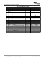
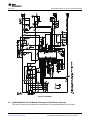
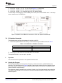
User's Guide
SLUU353 – June 2009
bq20z65EVM-001 SBS 1.1 Impedance Track™ Technology
Enabled Battery Management Solution Evaluation Module
This evaluation module (EVM) is a complete evaluation system for the bq20z65/bq29412 battery
management system. The EVM includes one bq20z65/bq29412 circuit module and a link to
Windows™-based PC software. The circuit module includes one bq20z65 integrated circuit (IC), one
bq29412 IC, and all other onboard components necessary to monitor and predict capacity, perform cell
balancing, monitor critical parameters, protect the cells from overcharge, over-discharge, short-circuit, and
overcurrent in 2-, 3- or 4-series cell Li-ion or Li-polymer battery packs. The circuit module connects directly
across the cells in a battery. With the EV2300 interface board and software, the user can read the
bq20z65 data registers, program the chipset for different pack configurations, log cycling data for further
evaluation, and evaluate the overall functionality of the bq20z65/bq29412 solution under different charge
and discharge conditions.
1
2
3
4
5
6
7
8
9
10
11
Contents
Features ....................................................................................................................... 2
bq20z65-Based Circuit Module ............................................................................................ 2
bq20z65 Circuit Module Schematic ....................................................................................... 3
Circuit Module Physical Layouts and Bill of Materials .................................................................. 3
EVM Hardware and Software Setup ...................................................................................... 8
Troubleshooting Unexpected Dialog Boxes .............................................................................. 8
Hardware Connection ....................................................................................................... 8
Operation ..................................................................................................................... 9
Calibration Screen.......................................................................................................... 12
Pro (Advanced) Screen .................................................................................................... 13
Related Documentation from Texas Instruments ...................................................................... 14
List of Figures
1
2
3
4
5
6
7
8
9
10
11
bq20z65EVM-001 Layout – Silk Screen .................................................................................. 4
Top Assembly ................................................................................................................ 4
Top Layer ..................................................................................................................... 4
Bottom Layer ................................................................................................................. 5
Bottom Assembly ............................................................................................................ 5
Schematic ..................................................................................................................... 7
bq20z65 Circuit Module Connection to Cells and System Load/Charger ............................................ 9
SBS Data Screen........................................................................................................... 10
Data Flash Screen, 1st Level Safety Class ............................................................................. 11
Calibration Screen.......................................................................................................... 13
Pro (Advanced) Screen .................................................................................................... 14
List of Tables
1
2
3
4
5
Ordering Information ........................................................................................................
Components and Flash-Memory Settings for Different Precharge Modes ...........................................
Bill of Materials ...............................................................................................................
Performance Specification Summary .....................................................................................
Circuit Module to EV2300 Connections ...................................................................................
SLUU353 – June 2009
Submit Documentation Feedback
bq20z65EVM-001 SBS 1.1 Impedance Track™ Technology
Enabled Battery Management Solution Evaluation Module
2
3
5
8
9
1
Features
1
Features
•
•
•
1.1
Complete evaluation system for the bq20z65 SBS 1.1-compliant advanced gas gauge with Impedance
Track™ technology and bq29412 independent overvoltage protection IC
Populated circuit module for quick setup
Software that allows data logging for system analysis
Kit Contents
•
•
1.2
www.ti.com
bq20z65/bq29412 circuit module
Set of support documentation
Ordering Information
Table 1. Ordering Information
2
EVM PART NUMBER
CHEMISTRY
CONFIGURATION
CAPACITY
bq20z65EVM-001
Li-ion
2, 3, or 4 cell
Any
bq20z65-Based Circuit Module
The bq20z65/bq29412-based circuit module is a complete and compact example solution of a bq20z65
circuit for battery management and protection of Li-ion or Li-polymer packs. The circuit module
incorporates a bq20z65 battery monitor IC, bq29412 independent overvoltage protection IC, and all other
components necessary to accurately predict the capacity of 2-, 3-, or 4-series cells.
2.1
Circuit Module Connections
Contacts on the circuit module provide the following connections:
• Direct connection to the cells: 1N (BAT-), 1P, 2P, 3P, 4P (BAT+)
• To the serial communications port (SMBC, SMBD)
• The system load and charger connect across PACK+ and PACK• To the system-present pin (SYS PRES)
2.2
Pin Descriptions
PIN NAME
DESCRIPTION
1N
-ve connection of first (bottom) cell
1P
+ve connection of first (bottom) cell
2P
+ve connection of second cell
3P
+ve connection of third cell
4P
+ve connection of fourth (top) cell
SMBC
Serial communication port clock
SMBD
Serial communication data port
SYS PRES
System present pin (if low, system is present)
PACK-
Pack negative terminal
VSS
Pack negative terminal
PACK+
Pack positive terminal
Impedance Track, bqEasy are trademarks of Texas Instruments.
Windows is a trademark of Microsoft Corporation.
2
bq20z65EVM-001 SBS 1.1 Impedance Track™ Technology
Enabled Battery Management Solution Evaluation Module
SLUU353 – June 2009
Submit Documentation Feedback
bq20z65 Circuit Module Schematic
www.ti.com
3
bq20z65 Circuit Module Schematic
This section contains information for modifying and choosing a precharge mode for bq20z65/bq29412
implementation.
3.1
Schematic
The schematic follows the bill of materials in this user's guide.
3.2
Modifications for Choosing Particular Precharge Mode
In order to charge, the charge FET (CHG-FET) must be turned on to create a current path. When the
V(BAT) is 0 V and CHG-FET = ON, the V(PACK) is as low as the battery voltage. In this case, the supply
voltage for the device is too low to operate. This function has three possible configurations, and the IC can
be easily configured according to the application needs. The three modes are 0-V Charge FET mode,
Common FET mode, and Precharge FET mode.
1. 0-V Charge FET mode - Dedicates a precharge current path using an additional FET (ZVCHG-FET) to
sustain the PACK+ voltage level.
2. Common FET mode - Does not use a dedicated precharge FET. The charge FET (CHG-FET) is set to
ON state as default.
3. Precharge FET mode - Dedicates a precharge current path using an additional open-drain (OD) pin
drive FET (PCHG-FET) to sustain the PACK+ voltage level.
To use a particular mode of charging with the EVM, add or remove some elements shown in Table 2, and
use the given settings of DF.Configuration, ZVCHG1, 0.
Table 2. Components and Flash-Memory Settings for Different Precharge
Modes
MODE
RESISTORS
PRECHG FET
ZVCHG1
ZVCHG0
1. 0-V Chg (default)
R21, R28
Q3
0
0
R24
Q2
0
1
R23, R28
Q3
1
0
2. Common FET
3. Precharge
For more details about precharge operation and mode choices, see the bq20z65 data sheet (SLUS878).
3.3
Testing Fuse-Blowing Circuit
To prevent the loss of board functionality during the fuse-blowing test, the actual chemical fuse is not
provided in the circuit. FET Q1 drives TP3 low if a fuse-blow condition occurs; so, monitoring TP3 can be
used to test this condition. Fuse placement on the application board is shown in the bq20z65 data sheet
reference-board schematic.
4
Circuit Module Physical Layouts and Bill of Materials
This section contains the printed-circuit board (PCB) layout, bill of materials, and assembly drawings for
the bq20z65/bq29412 circuit module.
SLUU353 – June 2009
Submit Documentation Feedback
bq20z65EVM-001 SBS 1.1 Impedance Track™ Technology
Enabled Battery Management Solution Evaluation Module
3
Circuit Module Physical Layouts and Bill of Materials
4.1
www.ti.com
Board Layout
This section shows the dimensions, PCB layers (Figure 1 through Figure 5), and assembly drawing for the
bq20z65 module.
Figure 1. bq20z65EVM-001 Layout – Silk Screen
Figure 2. Top Assembly
Figure 3. Top Layer
4
bq20z65EVM-001 SBS 1.1 Impedance Track™ Technology
Enabled Battery Management Solution Evaluation Module
SLUU353 – June 2009
Submit Documentation Feedback
Circuit Module Physical Layouts and Bill of Materials
www.ti.com
Figure 4. Bottom Layer
Figure 5. Bottom Assembly
4.2
Bill of Materials and Schematic
Table 3. Bill of Materials
Count
RefDes
Description
Size
Mfr
Part Number
21
C1–C9, C12,
C13, C15–C18,
C23, C24,
C26–C28
Capacitor, Ceramic, 0.1µF, 50 V, X7R, 20%
0603
Any
STD
1
C11
Capacitor, Ceramic, 0.22µF, 50 V, X7R, 20%
0603
Any
STD
1
C19
Capacitor, Ceramic, 4.7µF, 10 V, X7R, 20%
0603
Any
STD
1
C20
Capacitor, Ceramic, 47nF, 50 V, X7R, 20%
0603
Any
STD
2
C22, C25
Capacitor, Ceramic, 0.47µF, 16 V, X7R, 20%
0603
Any
STD
3
C10, C14, C21
Capacitor, Ceramic, 1.0µF, 25 V, X7R, 20%
0805
Any
STD
4
D1–D3, D11
Diode, Switching, 150-mA, 75-V, 350mW
SOT23
Vishay-Liteon
BAS16
2
D4, D5
Diode, Dual, Zener, 5.6V, 300mW
SOT23
VishayTelefunken
AZ23C5V6
5
D6–D10
Diode, LED, Green, Gullwing, GW Type, 20ma, 7.5
mcd typ.
0.120 × 0.087
inches
Panasonic
LN1361C
1
J1
Header, Friction Lock Ass'y, 4-pin Right Angle,
0.400 × 0.500
Molex
22-05-3041
1
Q1
MOSFET, N-ch, 20-V, 1.3A, 0.16-Ω
SOT23
Fairchild
NDS331N
2
Q2, Q4
MOSFET, N-ch Logic Level, Power Trench, 30V, 11A,
12.5 mΩ
SO8
Fairchild
FDS6690A
SLUU353 – June 2009
Submit Documentation Feedback
bq20z65EVM-001 SBS 1.1 Impedance Track™ Technology
Enabled Battery Management Solution Evaluation Module
5
Circuit Module Physical Layouts and Bill of Materials
www.ti.com
Table 3. Bill of Materials (continued)
6
Count
RefDes
Description
Size
Mfr
Part Number
1
Q3
MOSFET, P-ch, 30-V, 8.0-A, 20-mΩ
SO8
Siliconix
Si4435DY
1
Q6
MOSFET, Nch, 50V, 0.22A, 6 Ω
SOT23
Fairchild
BSS138
12
R1–R5, R12,
R13, R32–R34,
R38, R39
Resistor, Chip, 100-Ω, 1/16-W, 5%
0603
Std
Std
1
R11
Resistor, Chip, 0.010 Ω, 1-W, xx%
2512
Vishay
WSL-2512-010 1%
R86
3
R15, R16, R40
Resistor, Chip, 220 kΩ, 1/16-W, 5%
0603
Std
Std
1
R17
Resistor, Chip, 300-Ω, 1-W, 10%
2512
2
R18, R27
Resistor, Chip, 3.01MΩ, 1/16-W, 5%
0603
Std
Std
5
R14, R19,
R21–R23
Resistor, Chip, 5.1kΩ, 1/16-W, 5%
0603
Std
Std
4
R20, R36, R37,
R41
Resistor, Chip, 1MΩ, 1/16-W, 5%
0603
Std
Std
2
R24, R28
Resistor, Chip, 100kΩ, 1/16-W, 5%
0603
Std
Std
2
R25, R29
Resistor, Chip, 8.45kΩ, 1/16-W, 1%
0603
Std
Std
2
R26, R30
Resistor, Chip, 61.9kΩ, 1/16-W, 1%
0603
Std
Std
7
R6–R10, R31,
R35
Resistor, Chip, 1kΩ, 1/16-W, 5%
0603
Std
Std
2
RT1, RT2
Thermistor, 10kΩ
0.095 × 0.150
Semitec
NTC103AT
1
SW1
Switch, Push button, Momentary, N.O. Low Profile
5 mm × 5 mm
Panasonic
EVQPLCxxxx
2
TB1, TB4
Terminal Block, 2-pin, 6-A, 3,5mm
0.27 × 0.25
OST
ED1514
2
TB2, TB3
Terminal Block, 3-pin, 6-A, 3,5mm
0.41 × 0.25
OST
ED1515
1
TP1
Test Point, Black, Thru Hole Color Keyed
0.100 × 0.100 inch
Keystone
5001
1
TP3
Test Point, White, Thru Hole Color Keyed
0.100 × 0.100 inch
Keystone
5002
1
U1
IC, Voltage Protection for 2, 3, 4 Cell Lion , 2nd
Protection, 4.45 V OVP
SSOP-08
TI
BQ29412DCT
1
U2
IC, Cool-GG Programmable Battery Management
TSSOP30
TI
bq20z65DBT
bq20z65EVM-001 SBS 1.1 Impedance Track™ Technology
Enabled Battery Management Solution Evaluation Module
WSL-2512-300 1%
R86
SLUU353 – June 2009
Submit Documentation Feedback
www.ti.com
Circuit Module Physical Layouts and Bill of Materials
Figure 6. Schematic
4.3
bq20z65/bq29412 Circuit Module Performance Specification Summary
This section summarizes the performance specifications of the bq20z65/bq29412 circuit module.
SLUU353 – June 2009
Submit Documentation Feedback
bq20z65EVM-001 SBS 1.1 Impedance Track™ Technology
Enabled Battery Management Solution Evaluation Module
7
EVM Hardware and Software Setup
www.ti.com
Table 4. Performance Specification Summary
Specification
5
Minimum
Typical
Maximum
Units
Input voltage Pack+ to Pack–
6
15
25
V
Charge and discharge current
0
2
7
A
EVM Hardware and Software Setup
This section describes how to install the bq20z65 PC software and how to connect the different
components of the EVM.
5.1
System Requirements
The bq20z65EVSW software requires Windows™ 2000 or Windows XP.
5.2
Software Installation
Find the latest software version in the bq20z65 tool folder on power.ti.com. Use the following steps to
install the bq20z65EVSW software:
1. Copy the files from the Ti Web site into a temporary directory you select, double-click on
bqEV-EASYSetup00.09.xx.exe, where xx indicates the version, and follow the installer instructions to
complete the bq20z60 EVSW installation.
2. If the EV2300 was not previously installed, after bq20z60 EVSW installation, a TI USB DRIVER
INSTALLER pops up. Click Yes for the agreement message and follow its instructions. Two drivers are
associated with the EV2300. Follow the instructions to install both. Do not reboot the computer, even if
asked to do so.
3. Plug the EV2300 into a USB port. The Windows system may show a prompt that new hardware has
been found. When asked, "Can Windows connect to Windows Update to search for software?", select
"No, not this time" and click on NEXT. In the next dialog window, it indicates "This wizard helps you
install software for: TI USB Firmware Updater", select "Install the software automatically
(Recommended)" and click NEXT. It is common for the next screen to be the Confirm File Replace
screen. Click No to continue. If this screen does not appear, then go to the next step. After Windows
indicates that the installation was finished, a similar dialog window pops up to install the second driver;
proceed with the same installation preference as the first one. The second driver is TI USB bq80xx
Driver.
6
Troubleshooting Unexpected Dialog Boxes
The following actions can help the user to avoid unexpected dialog boxes.
• Ensure that the files were extracted from the zip file using the Preserve Folder names option.
• Ensure that all the files were extracted from the zip file.
• The user that is downloading the files must be logged in as the administrator.
• The driver is not signed, so the administrator must allow installation of unsigned drivers in the
operating system policy.
7
Hardware Connection
The bq20z65EVM-001 comprises three hardware components: the bq20z65/bq29412 circuit module, the
EV2300 PC interface board, and the PC.
7.1
Connecting bq20z65/bq29412 Circuit Module to Battery Pack
Figure 7 shows how to connect the bq20z65/bq29412 circuit module to the cells and system load/charger.
The cells must be connected in the following order:
8
bq20z65EVM-001 SBS 1.1 Impedance Track™ Technology
Enabled Battery Management Solution Evaluation Module
SLUU353 – June 2009
Submit Documentation Feedback
Operation
www.ti.com
1. 4-Cell Pack: 1N (BAT–), 1P, 2P, 3P, and 4P (see Section 2.1 for definitions).
2. 3-Cell Pack: 1N (BAT–), 1P, 2P, and then connect 4P and 3P together.
3. 2-Cell Pack: 1N (BAT–), 1P, and then connect 4P, 3P, and 2P together
To start charge or discharge test, connect PRES pin to PACK- pin to set SYS PRES state. To test sleep
mode, disconnect the SYS PRES pin.
Figure 7. bq20z65 Circuit Module Connection to Cells and System Load/Charger
7.2
PC Interface Connection
The following steps configure the hardware for interface to the PC:
1. Connect the bq20z65-based smart battery to the EV2300 using wire leads as shown in Table 5.
Table 5. Circuit Module to EV2300 Connections
bq20z65-Based Battery
EV2300
SMBD
SMBD
SMBC
SMBC
VSS
GND
2. Connect the PC USB cable to the EV2300 and the PC USB port.
The bq20z65EVM-001 is now set up for operation.
8
Operation
This section details the operation of the bq20z65 EVSW software.
8.1
Starting the Program
Run bq Evaluation Software from the Start | Programs | Texas Instruments | bq20z65 EVSW menu
sequence. The SBS Data screen (Figure 8) appears. Data begins to appear once the <Refresh> (single
time scan) button is clicked, or when the <Keep Scanning> check box is checked. To disable the scan
feature, deselect <Keep Scanning>.
The continuous scanning period can be set via the | Options | and | Set Scan Interval | menu selections.
The range for this interval is 0 ms to 65535 ms. Only items that are selected for scanning are scanned
within this period.
SLUU353 – June 2009
Submit Documentation Feedback
bq20z65EVM-001 SBS 1.1 Impedance Track™ Technology
Enabled Battery Management Solution Evaluation Module
9
Operation
www.ti.com
The bq Evaluation Software provides a logging function which logs the values that were last scanned by
EVSW. To enable this function, select the Start Logging button; this causes the Keep Scanning button to
be selected. When logging is Stopped, the keep scanning button is still selected and has to be manually
unchecked.
The logging intervals are specified under the | Options | menu with the maximum value of 65535 ms. The
Log interval cannot be smaller than the scan interval because this results in the same value being logged
at least twice.
Figure 8. SBS Data Screen
This screen (Figure 8) shows the SBS data set along with additional ManufacturersAccess() command
information such as individual cell measurements. Additional Flag and Static data can be viewed by
selecting the appropriate tab at the bottom of the SBS screen.
Data such as SBS.ManufacturerName() is static and does not change. This data is viewed separately
using the Static Data tab available at the bottom of the screen.
Dragging the splitter bar (line that separates the Flags/Static data from SBS values) changes the height of
the Flags/Static Data display. Selecting | View |, then | Auto Arrange | returns the splitter bar to its original
location.
10
bq20z65EVM-001 SBS 1.1 Impedance Track™ Technology
Enabled Battery Management Solution Evaluation Module
SLUU353 – June 2009
Submit Documentation Feedback
Operation
www.ti.com
8.2
Setting Programmable bq20z65 Options
The bq20z65 data flash comes configured per the default settings detailed in the bq20z65 data sheet.
Ensure that the settings are correctly changed to match the pack and application for the bq20z65 solution
being evaluated.
IMPORTANT: The correct setting of these options is essential to get the best performance.
The settings can be configured using the Data Flash screen (Figure 9).
Figure 9. Data Flash Screen, 1st Level Safety Class
To read all the data from the bq20z65 data flash, click on menu option | Data Flash | Read All |.
To write to a data flash location, click on the desired location, enter the data and press <Enter>, which
writes the entire tab of flash data, or select menu option | Data Flash | Write All |. The data flash must be
read before any writes are performed to avoid any incorrect data being written to the device.
The | File | Special Export | menu option allows the data flash to be exported, but it configures the
exported data flash to a learned state ready for mass production use.
The data flash configuration can be saved to a file by selecting | File | Export | and entering a file name. A
data flash file also can be retrieved in this way, imported, and written to the bq20z65 using the | Write All |
button.
The configuration information of the bq29z95 and module calibration data also is held in the bq20z65 data
flash.
SLUU353 – June 2009
Submit Documentation Feedback
bq20z65EVM-001 SBS 1.1 Impedance Track™ Technology
Enabled Battery Management Solution Evaluation Module
11
Calibration Screen
www.ti.com
The bq20z65 allows for an automatic data flash export function, similar to the SBS Data logging function.
This feature, when selected via | Options | Auto Export |, exports Data Flash to a sequential series of files
named as FilenameNNNNN.gg where N = a decimal number from 0 to 9.
The AutoExport interval is set under the | Options menu | with a minimum value of 15 s. The AutoExport
filename also is set under the | Options menu |.
When a check mark is next to | AutoExport |, the AutoExport is in progress. The same menu selection is
used to turn on/off AutoExport.
If the data flash screen is blank, then the bq20z65 that is being used may not be supported by the
bqEVSW version that is being used. An upgrade may be required.
9
Calibration Screen
9.1
How to Calibrate
The bq20z65 must be calibrated using power supplies or a power supply and cell simulation resistors (200
Ω to 1000 Ω each) before cells are attached. Before the bq20z65 is calibrated:
• Connect and measure a 2-A current source from 1N (-) and Pack- (+) to calibrate without using the
FETs. (Calibration using the FETs is not recommended.)
• Measure the pack voltage from Batt+ to Batt- (total of cell voltages).
• Measure the temperature of the pack.
• These steps may not be required, depending on the type of calibration being performed.
9.2
To Calibrate the bq20z65
Perform the following steps.
1. Select the types of calibration to be performed (see Figure 10).
2. Enter the measured values for the types selected (except for CC Offset Calibration).
3. If Voltage Calibration is selected, then enter the number of cells on the pack.
4. If Temperature Calibration is selected, then select the sensor that is to be calibrated.
5. If the current source is connected between 1N and Pack-, then select the Off (bypassed) check box in
the FET Control section.
6. Press the Calibrate Part button.
9.3
Board Offset Calibration
The following steps perform the offset calibration for the current offset of the board.
1. Remove load/external voltage and short Pack- to Batt-.
2. Press the CC Board Offset Calibration button.
9.4
Pack Voltage Calibration
The following steps calibrate the voltage at the AFE Pack pin.
1. Ensure that Voltage Calibration has been performed for the pack. Ensure that a stable charger voltage
higher than 8-V is present at Pack+.
2. Press the Pack Voltage button to calibrate.
12
bq20z65EVM-001 SBS 1.1 Impedance Track™ Technology
Enabled Battery Management Solution Evaluation Module
SLUU353 – June 2009
Submit Documentation Feedback
Pro (Advanced) Screen
www.ti.com
Figure 10. Calibration Screen
10
Pro (Advanced) Screen
10.1 SMB Communication
The set of read/write operations over SMBus are not specific to any gas gauge. These are provided as
general-purpose communication tools (Figure 11).
10.2 Hexadecimal/Decimal Converter
These two boxes convert between hexadecimal and decimal as soon as values are typed into the boxes.
Invalid values may cause erroneous results.
When scaling converted hexadecimal values to a higher number of bytes, follow these rules:
• When unsigned is selected, the left pad contains zeroes.
• When signed is selected, the left pad contains zeroes for a positive number, or the left pad contains F
for negative numbers.
SLUU353 – June 2009
Submit Documentation Feedback
bq20z65EVM-001 SBS 1.1 Impedance Track™ Technology
Enabled Battery Management Solution Evaluation Module
13
Related Documentation from Texas Instruments
www.ti.com
10.3 Programming
This screen allows device reprogramming from unencrypted and encrypted files.
Figure 11. Pro (Advanced) Screen
11
Related Documentation from Texas Instruments
1. bq20z95, SBS 1.1-Compliant Gas Gauge Enabled and Protection Enabled With Impedance Track™
data sheet (SLUS757)
2. bq20z90-V1.50 + bq29330, bq20z95 Technical Reference manual (SLUU264)
3. bq20z70 and bq20z90 Application Book (SLUA404)
4. Quick-Start Guide for bq20zxx Family Gas Gauge application report (SLUA421)
5. bqEasy™ User's Guide (SLUU278)
14
bq20z65EVM-001 SBS 1.1 Impedance Track™ Technology
Enabled Battery Management Solution Evaluation Module
SLUU353 – June 2009
Submit Documentation Feedback
EVALUATION BOARD/KIT IMPORTANT NOTICE
Texas Instruments (TI) provides the enclosed product(s) under the following conditions:
This evaluation board/kit is intended for use for ENGINEERING DEVELOPMENT, DEMONSTRATION, OR EVALUATION PURPOSES
ONLY and is not considered by TI to be a finished end-product fit for general consumer use. Persons handling the product(s) must have
electronics training and observe good engineering practice standards. As such, the goods being provided are not intended to be complete
in terms of required design-, marketing-, and/or manufacturing-related protective considerations, including product safety and environmental
measures typically found in end products that incorporate such semiconductor components or circuit boards. This evaluation board/kit does
not fall within the scope of the European Union directives regarding electromagnetic compatibility, restricted substances (RoHS), recycling
(WEEE), FCC, CE or UL, and therefore may not meet the technical requirements of these directives or other related directives.
Should this evaluation board/kit not meet the specifications indicated in the User’s Guide, the board/kit may be returned within 30 days from
the date of delivery for a full refund. THE FOREGOING WARRANTY IS THE EXCLUSIVE WARRANTY MADE BY SELLER TO BUYER
AND IS IN LIEU OF ALL OTHER WARRANTIES, EXPRESSED, IMPLIED, OR STATUTORY, INCLUDING ANY WARRANTY OF
MERCHANTABILITY OR FITNESS FOR ANY PARTICULAR PURPOSE.
The user assumes all responsibility and liability for proper and safe handling of the goods. Further, the user indemnifies TI from all claims
arising from the handling or use of the goods. Due to the open construction of the product, it is the user’s responsibility to take any and all
appropriate precautions with regard to electrostatic discharge.
EXCEPT TO THE EXTENT OF THE INDEMNITY SET FORTH ABOVE, NEITHER PARTY SHALL BE LIABLE TO THE OTHER FOR ANY
INDIRECT, SPECIAL, INCIDENTAL, OR CONSEQUENTIAL DAMAGES.
TI currently deals with a variety of customers for products, and therefore our arrangement with the user is not exclusive.
TI assumes no liability for applications assistance, customer product design, software performance, or infringement of patents or
services described herein.
Please read the User’s Guide and, specifically, the Warnings and Restrictions notice in the User’s Guide prior to handling the product. This
notice contains important safety information about temperatures and voltages. For additional information on TI’s environmental and/or
safety programs, please contact the TI application engineer or visit www.ti.com/esh.
No license is granted under any patent right or other intellectual property right of TI covering or relating to any machine, process, or
combination in which such TI products or services might be or are used.
FCC Warning
This evaluation board/kit is intended for use for ENGINEERING DEVELOPMENT, DEMONSTRATION, OR EVALUATION PURPOSES
ONLY and is not considered by TI to be a finished end-product fit for general consumer use. It generates, uses, and can radiate radio
frequency energy and has not been tested for compliance with the limits of computing devices pursuant to part 15 of FCC rules, which are
designed to provide reasonable protection against radio frequency interference. Operation of this equipment in other environments may
cause interference with radio communications, in which case the user at his own expense will be required to take whatever measures may
be required to correct this interference.
EVM WARNINGS AND RESTRICTIONS
It is important to operate this EVM within the input voltage range of 6 V to 25 V and the output voltage range of 0 V to 16.4 V.
Exceeding the specified input range may cause unexpected operation and/or irreversible damage to the EVM. If there are questions
concerning the input range, please contact a TI field representative prior to connecting the input power.
Applying loads outside of the specified output range may result in unintended operation and/or possible permanent damage to the EVM.
Please consult the EVM User's Guide prior to connecting any load to the EVM output. If there is uncertainty as to the load specification,
please contact a TI field representative.
During normal operation, some circuit components may have case temperatures greater than 60°C. The EVM is designed to operate
properly with certain components above 60°C as long as the input and output ranges are maintained. These components include but are
not limited to linear regulators, switching transistors, pass transistors, and current sense resistors. These types of devices can be identified
using the EVM schematic located in the EVM User's Guide. When placing measurement probes near these devices during operation,
please be aware that these devices may be very warm to the touch.
Mailing Address: Texas Instruments, Post Office Box 655303, Dallas, Texas 75265
Copyright © 2009, Texas Instruments Incorporated
IMPORTANT NOTICE
Texas Instruments Incorporated and its subsidiaries (TI) reserve the right to make corrections, modifications, enhancements, improvements,
and other changes to its products and services at any time and to discontinue any product or service without notice. Customers should
obtain the latest relevant information before placing orders and should verify that such information is current and complete. All products are
sold subject to TI’s terms and conditions of sale supplied at the time of order acknowledgment.
TI warrants performance of its hardware products to the specifications applicable at the time of sale in accordance with TI’s standard
warranty. Testing and other quality control techniques are used to the extent TI deems necessary to support this warranty. Except where
mandated by government requirements, testing of all parameters of each product is not necessarily performed.
TI assumes no liability for applications assistance or customer product design. Customers are responsible for their products and
applications using TI components. To minimize the risks associated with customer products and applications, customers should provide
adequate design and operating safeguards.
TI does not warrant or represent that any license, either express or implied, is granted under any TI patent right, copyright, mask work right,
or other TI intellectual property right relating to any combination, machine, or process in which TI products or services are used. Information
published by TI regarding third-party products or services does not constitute a license from TI to use such products or services or a
warranty or endorsement thereof. Use of such information may require a license from a third party under the patents or other intellectual
property of the third party, or a license from TI under the patents or other intellectual property of TI.
Reproduction of TI information in TI data books or data sheets is permissible only if reproduction is without alteration and is accompanied
by all associated warranties, conditions, limitations, and notices. Reproduction of this information with alteration is an unfair and deceptive
business practice. TI is not responsible or liable for such altered documentation. Information of third parties may be subject to additional
restrictions.
Resale of TI products or services with statements different from or beyond the parameters stated by TI for that product or service voids all
express and any implied warranties for the associated TI product or service and is an unfair and deceptive business practice. TI is not
responsible or liable for any such statements.
TI products are not authorized for use in safety-critical applications (such as life support) where a failure of the TI product would reasonably
be expected to cause severe personal injury or death, unless officers of the parties have executed an agreement specifically governing
such use. Buyers represent that they have all necessary expertise in the safety and regulatory ramifications of their applications, and
acknowledge and agree that they are solely responsible for all legal, regulatory and safety-related requirements concerning their products
and any use of TI products in such safety-critical applications, notwithstanding any applications-related information or support that may be
provided by TI. Further, Buyers must fully indemnify TI and its representatives against any damages arising out of the use of TI products in
such safety-critical applications.
TI products are neither designed nor intended for use in military/aerospace applications or environments unless the TI products are
specifically designated by TI as military-grade or "enhanced plastic." Only products designated by TI as military-grade meet military
specifications. Buyers acknowledge and agree that any such use of TI products which TI has not designated as military-grade is solely at
the Buyer's risk, and that they are solely responsible for compliance with all legal and regulatory requirements in connection with such use.
TI products are neither designed nor intended for use in automotive applications or environments unless the specific TI products are
designated by TI as compliant with ISO/TS 16949 requirements. Buyers acknowledge and agree that, if they use any non-designated
products in automotive applications, TI will not be responsible for any failure to meet such requirements.
Following are URLs where you can obtain information on other Texas Instruments products and application solutions:
Products
Amplifiers
Data Converters
DLP® Products
DSP
Clocks and Timers
Interface
Logic
Power Mgmt
Microcontrollers
RFID
RF/IF and ZigBee® Solutions
amplifier.ti.com
dataconverter.ti.com
www.dlp.com
dsp.ti.com
www.ti.com/clocks
interface.ti.com
logic.ti.com
power.ti.com
microcontroller.ti.com
www.ti-rfid.com
www.ti.com/lprf
Applications
Audio
Automotive
Broadband
Digital Control
Medical
Military
Optical Networking
Security
Telephony
Video & Imaging
Wireless
www.ti.com/audio
www.ti.com/automotive
www.ti.com/broadband
www.ti.com/digitalcontrol
www.ti.com/medical
www.ti.com/military
www.ti.com/opticalnetwork
www.ti.com/security
www.ti.com/telephony
www.ti.com/video
www.ti.com/wireless
Mailing Address: Texas Instruments, Post Office Box 655303, Dallas, Texas 75265
Copyright © 2009, Texas Instruments Incorporated