1
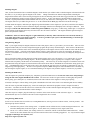
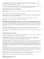
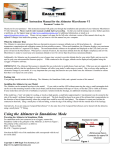
Instruction Manual for the USB Car Data Recorder
Patent Pending
Document Version 2.6, Model # CDR-01
Thank you for your purchase! This instruction manual will guide you through the installation and operation of
your Car Data Recorder.
Please read the entire manual carefully before proceeding. If, after you read the manual (including the
Troubleshooting sections!) you have further questions or problems, please visit our web support page for additional
support options, at http://www.eagletreesystems.com/Support/support.html. Note that the latest version of this
manual is available in PDF form from the Support page of our website.
Steps to Follow
Installation and use of the Car Data Recorder will be quite easy and enjoyable if you follow these few steps:
1.
2.
3.
4.
Read through the manual to understand the warnings, determine what parameters you want to log, etc.
Install the Recorder in your model, as described in the Recorder Installation section below. Pay special attention to the
polarity and plug-in location of the sensors, since some of the plugs will fit in more than one location!
Install and configure the Windows software as described in the Windows installation section below. Note that you will need
to bring your model near your computer for this step.
Bench and range test your model, and have fun!
Packing List
Your package should include the following: Car Data Recorder, 2 ‘Y’ Cables, 1 Temperature Sensor, 1 RPM sensor, 4 tiny magnets,
Custom USB Cable, and CD-ROM.
Installation of the Recorder
NOTE: The recorder’s label has a handy color coded means of indicating the polarity of the various connectors. The red dots on
the label, which are on only one side of the text corresponding to each input, indicate on which side of the plug the red wire
should go.
Powering the Recorder and Connecting the Recorder to Your Model’s Servos and Receiver
First, determine if you wish to log servo positions. If you decide to log servo positions, you will be connecting the Recorder to your
receiver via the ‘Y’ cables. In this configuration, the Recorder is powered from your receiver battery.
If you decide not to log servo positions, you can still power the Recorder from your receiver battery by connecting one of the Y cables
from a spare receiver channel to the Recorder (or use your own 2-3 wire connector).
If you want to power the Recorder from a separate battery, meaning that you want complete electrical isolation between the Recorder
and your receiver, you can power the Recorder with a small separate battery as described in the Installing Battery Backup Harness
section below.
Copyright © 2003 Eagle Tree Systems, LLC
http://www.eagletreesystems.com
Page 2
The Recorder includes two custom, heavy duty ‘Y’ cables with Universal connectors which install in line between your
throttle and steering servos and your radio receiver. Connection of the ‘Y’ cables is simple: connect the center (male) keyed
connector of the ‘Y’ to one of the 2 keyed slots servo slots in the recorder (see Figure 1), connect the remaining male connector one of
the channels on your receiver, and connect the female ‘Y’ connector to the servo which you previously connected to that channel of
the receiver. Note: It doesn’t matter which of the 2 keyed recorder slots you plug your ‘Y’ cables into – the Recorder Application
will automatically detect which servos are connected where during application setup.
WARNING: Do not connect ‘Y’ cables to any other location on the recorder. Doing so may damage the recorder or other
components.
Note: the Recorder, which draws only around 35 mA of current, draws power from the ‘Y’ cables. All standard receivers we are
aware of hardwire the power and ground wires from the battery to the power and ground wires of the servos, so the Recorder is in
reality directly connected to the battery.
Note: The ‘Y’ cables included should be electrically compatible with most of the currently available receivers, such as Futaba™,
JR™, Tower™, and HiTec™.
The pinout of the ‘Y” cables is as follows: Black = ground, Red = power, White = servo signal
WARNING: It is your responsibility to make sure that your receiver and servos are pin compatible with the Y cables before
connecting. Serious damage could result to your receiver, servo or recorder if they are not compatible. If your equipment is
not pin compatible, you should obtain the appropriate connector adapter from your hobby shop.
Installing the Temperature Sensor(s)
One temperature sensor is included with the Recorder – an additional
sensor can be ordered separately. The temperature sensors are typically
installed by placing the black wire loop around the cylinder head, and
cinching it in place by pulling the two rubber stays snugly against the
engine. Normally the highest temperatures are experienced near the base
of the engine, but experience will dictate where your particular engine
best reads heat. Other mounting arrangements are possible, such as
obtaining a metal washer with a tab, carefully bending the tab around the
sensor portion of the wire loop, and installing the washer under your
glow plug, or installing the sensor under a dedicated tapped screw in the
cylinder head. Note that since various mounting locations and brands of
temperature devices on the market will read differently, the most
important aspect of temperature measurement is learning how your
engine reads under various conditions, and adjusting based on relative
temperature readings.
Plug the Futaba style connector from the sensor
into the recorder as shown in Figure 1.
Installing the RPM Sensor and Magnets
Installing the RPM sensor and magnets is the most challenging part of installation, but is
relatively easy once a good mounting location is determined. Refer to our website’s Car
support page at http://www.eagletreesystems.com for pictures of example installations.
First, find a suitable location on your Car’s drivetrain to attach one or two small magnets and
RPM sensor. Typically, on nitro motors the flywheel is an ideal location. On electric cars
the driveshaft or one of the axles is the best place. This will of course vary with make and
model of Car. Make sure the magnets are mounted on some structure that doesn’t “flop
around,” as the magnets could hit the sensor in this case. The RPM sensor must be mounted
so that it does not move around, and is within 1-2 mm of the two magnets as they spin. On
typical Car installations, there’s usually a place where the back of the sensor can be glued to a
flat surface under or over the hub which has the magnets mounted. The Recorder kit
includes four magnets, providing you with up to three spares.
Figure 2: RPM Sensor & Magnet
Copyright © 2003 Eagle Tree Systems, LLC
http://www.eagletreesystems.com
Page 3
Installing Magnets
Once you have determined where to install the magnets, decide whether you will drill a hole so that the magnets will mount flush with
the surface, or if you will just glue the magnets to the surface. Though somewhat more difficult and permanent, mounting the
magnet flush with the surface is the best long term approach, since the mounting will be much more rugged, and the risk of imbalance
due to not mounting the magnets exactly 180 degrees apart is reduced. In fact, if the magnet is mounted flush in another metal
material, it is quite possible that no shaft imbalance will occur if you only mount one of the magnets total. If you decide to use only
one magnet, make sure you double the gear ratio to “2” on the Calibrate Motor RPM page under the Tools menu in the app.
To flush mount the magnets, drill a hole just slightly larger than the diameter of the magnet size you choose, and of the same depth as
that magnet. If you decide to surface mount the magnets, thoroughly clean this area and lightly scuff it to improve adhesion. Glue
the magnets with the side marked with a red line facing inward (hidden), using epoxy, or other strong, suitable glue. It’s important
that the red line on the magnets faces away from the sensor once the sensor is installed. The magnets should be glued 180 degrees
apart to keep the shaft in balance.
WARNING: make sure that the magnets are glued sufficiently so that they will not detach and create a hazard, and always
wear safety glasses when your engine is running! It is also a good idea to put a piece of heatshrink tubing or electrical tape
around the magnets, to further secure them.
Using Existing Magnets
Note: if your engine already has magnets mounted for some other purpose, there’s a good chance you can use them. Take one of the
magnets included with your recorder, and put that magnet up against the previously mounted magnet. If the red line of the Recorder
magnet faces down so that the sensor can be mounted facing the side of the magnet with no red line, mount the sensor with the printed
side toward the magnet. If the side of the magnet with the red line is visible when on top of the previous magnet, the polarity is
reversed. This should work correctly if you install our sensor backwards (printed side of sensor away from magnets), though we have
not tried it.
We are often asked whether existing magnets on spark ignition engines can be used. The answer is “yes” in most cases, if you can
install the sensor near enough to rotating magnets. We have found that these engines typically have 3 magnets, with 2 magnets
mounted with one polarity, and the other one with another polarity. The easiest way to use these magnets is to install the sensor with
the printed side facing the magnets (as described below) then run the motor and see what RPMs are recorded after setting up the gear
ratio. If the RPM looks like it is only half of the correct value, double the gear ratio value you entered, to compensate for only one
magnet being in the right polarity. We have received problem reports of RPM reading errors when the RPM sensor is mounted very
near the magneto of spark engines, so we recommend mounting it 180 degrees away from the magneto, or as far away as possible.
Installing the RPM Sensor
Once the magnets are glued and completely dry, temporarily position the RPM sensor so that the side of the sensor with printing is
facing the side of the magnets WITHOUT the red line. The sensor now needs to be glued so that it is held rigidly into position.
Before gluing, put a small spacer (1-2 mm thick) between the sensor and one of the magnets to ensure proper spacing.
If desired, a small piece of brass tubing can be glued or heatshrunk to the back of the sensor to ease mounting and increase stability.
After the sensor is glued and completely dry, remove the small spacer and rotate the propeller to ensure complete freedom of
movement. Also make sure that the sensor won’t vibrate and come in contact with the magnets during driving. If this happens, the
sensor will be destroyed, and the Recorder could be damaged.
Once these steps are complete, plug the Futaba style connector on the sensor into the recorder as shown in figure 1.
standard Futaba style servo extension cable can be used to lengthen the wire if needed.
Note that a
Using Existing RPM Sensors
Several of our customers have been able to use existing RPM sensors, such as governors or turbine sensors, with our products.
following steps must be followed:
The
1) Determine the “pinout” of the existing sensor. Compatible sensors will have Power, Ground, and Signal connections. The
Recorder’s RPM pinout, from left to right, is: Power (black wire), Ground (red wire), Signal (white wire).
2) Devise a “Y” cable to connect your existing sensor to it’s connection, and also to the Recorder’s RPM connection. NOTE:
Power for the sensor should come only from the connection the sensor is normally plugged into. So, only Gound and Signal
Copyright © 2003 Eagle Tree Systems, LLC
http://www.eagletreesystems.com
Page 4
wires should be routed from the existing sensor to the recorder. The power wire of the Y cable between the
sensor and the recorder should be cut before connecting it to the recorder. This is necessary to avoid connecting the power
of the existing sensor connection to the Recorder’s power connection.
3) Thoroughly test the system to make sure the sensor still works with whatever it was originally connected to, after Y’ing to the
recorder.
Installing a Secondary RPM Sensor
A second MODIFIED RPM sensor can be plugged into the unused servo port nearest the switch on the recorder, for measuring wheel
slip or other parameters. This RPM sensor must be modified by swapping the red and black wires in the RPM sensor plug.
Carefully pry back the plastic tabs that hold each pin in the plug, remove the red and black pins, and re-install them so that the pin
order is RED, BLACK, WHITE. The second RPM sensor plugs into the servo port with the red wire to the right, nearest the edge of
the recorder.
NOTE: for the secondary RPM sensor to work, there has to be voltage from 4.5 to 6.5 V supplied to one or both of the servo inputs (as
shown in Figure 1). This is normally done with the Y Cables, a separate battery, or your BEC.
The second RPM channel is set up in the “Secondary RPM Sensor Setup” section under “Tools, Calibrate Speed from RPM.”
Normally, if the second RPM is used for wheel speed, just enter a “1” in this field if you are using 2 magnets, or a “2” if you are using
only one magnet.
The secondary RPM sensor is logged and displayed on the screens with the other parameters, as described below.
Installing the Optional Battery Backup Harness
In most cases, the Recorder can be successfully powered by the Y cables from the receiver. If you have problems with recorder
power during acceleration or steering, as described in the troubleshooting section, this can be remedied by adding a small backup
battery to power the recorder. To add the backup battery, plug the larger end of the optional backup harness into the recorder. The
backup harness is a two wire cable with a Futaba style male connector on one end, and a larger male connector on the other end.
The large end of the backup harness plugs into the USB port of the recorder, with the red wire in the same place as the red wire of the
USB cable (as shown in the drawing).
The backup battery must be at least 4.5volts to power the recorder. Power is only drawn from the backup battery when the voltage
being supplied through the Y cables drops below the voltage of the backup battery, so if you use a 4.5 volt backup battery, no power
should be drawn from it except for moments when the main battery drops below this voltage. Therefore, it is possible to use a very
small pack (a tiny 4 cell pack or possibly 3 watch type batteries) as the backup battery. Note of course that the backup battery must
be disconnected whenever the receiver is turned off, as it will power the recorder whenever power is not supplied to the recorder from
the receiver. If you want to get fancy, you could add a DPDT switch in place of the standard receiver switch and turn off the backup
battery whenever you turn off the receiver.
Removing the Recorder from your Car
When you remove the Recorder, your servos are still connected to your receiver so it’s not necessary to remove the ‘Y’ cables from
the car to operate it without the Recorder. Be sure however that the connectors are kept from shorting.
Note: Additional ‘Y’ cables, RPM sensors and temperature sensors are available for purchase on our website if you wish to install
and leave ‘Y’ cables in more than one car. This makes it very easy to use the same recorder with multiple cars.
Installation and Use of the Windows™ Application
Installing the Windows Application
The supplied Windows application is compatible with USB equipped PCs running Windows 98SE, Millennium, Win 2K, and Win
XP. The application is not compatible with Windows 98 Original Edition (Gold), or NT 4, even if the PC has USB support.
NOTE: the application included on CD with the unit was current at the time of manufacture. Please check our Car Support page on
http://eagletreesystems.com to see if there is a newer version of the app which may have addressed issues you could encounter.
Copyright © 2003 Eagle Tree Systems, LLC
http://www.eagletreesystems.com
Page 5
To install the application, just place the CD in the CD-ROM drive. If AutoPlay is enabled on your PC, the setup
program should run automatically. If it does not run, click on My Computer, click on the icon for your CD-ROM drive, and click on
the “Car Data Recorder” application icon in the drive window.
Follow the Setup Wizard to install the Recorder application. Once installation is complete, the Recorder may be launched either from
its Desktop Icon, or by choosing the Recorder application from the Start->Programs->Eagle Tree Systems folder.
Setting up the Recorder with the Application
Once the application is installed, follow the above steps to launch it. The first time the application is launched, the New Car Wizard
will be invoked.
The Wizard will prompt you to install the Recorder using the supplied USB cable.
Warning: Make sure you connect the custom USB plug with the correct polarity, and into the correct connector on the Recorde,
as shown in Figure 1 r. Not doing this could cause damage!
When you do this for the first time, the behavior will be different depending on which version of Windows you are using:
Windows 98™: The Recorder and application are not compatible with Windows 98.
Windows 98SE™ and Windows Millennium™: When the Recorder is first connected to the USB port, the New Hardware Wizard
will likely appear. Follow the steps in the Wizard, choosing the options to allow Windows to find the appropriate drivers for the
Recorder – these drivers are built into Windows. If the devices you already have on your computer haven’t required the installation
of the USB drivers, Windows will prompt you for your Windows CD to copy over the drivers. Once this process is complete, you
may be asked to reboot the system. Reboot at this point, then relaunch the Recorder Application, and the New Car Wizard should
start up again.
Windows 2000 ™ and Windows XP ™: When the Recorder is first connected to the USB port, Windows should automatically
install the correct drivers without prompting you. If you should receive a Windows prompt, however, do what it says.
Once the Recorder is correctly discovered and installed by Windows, continue on with the New Car Wizard, relaunching the app after
reboot if necessary.
Telling the Recorder what to Log
The first time you run the app, you will be prompted to choose what driving parameters you wish to log. The more items you log, the
less record time will be available. A description of the parameters is below:
Steering and Throttle movements: If one or more of these parameters is checked, the recorder will log the positions of the
corresponding servos. Choose these options if you want to see controller movements while racing, etc. Logging the steering
movements may make it easy to track where you were on a track when particular events occur.
Receiver Battery Voltage: Selecting this parameter causes the recorder to log your receiver’s battery voltage (or whatever battery is
being used to power the servos). Note that it is normal to see rapid spikes in the receiver battery voltage on playback, but if you are
seeing voltage drops below 4.5 volts on a regular basis, you should test your battery. The Recorder constantly monitors battery
voltage even if this option is not checked, and will shut itself down if the battery voltage consistently is below around 4.5 volts to save
power for the receiver. The recorder will log an error in this case. The recorder will “reboot” if the voltage falls below 4.35 volts
even for a short period, and logs an error in this case also. Error logs are displayed in the “Notification Area” of the application
during playback.
Servo Glitches: If this option is selected, the recorder detects and logs three different types of servo glitches: short servo pulses (less
than 740uSec), long servo pulses (greater than 2.25 mSec) and missing servo pulses (no pulse for 100mSec). The most common
causes of glitches are low receiver or transmitter battery, driving out of range of your transmitter, or defective receiver. Note that it is
normal to see a series of glitch notifications right after the recorder or the transmitter is powered up.
RPM: If this option is selected, the recorder logs the RPM of your car. Note that for speed to function, RPM must be logged. Note
also that the parameters in the “Calibrate Speed to RPM” must also be set up to measure RPM correctly.
Temperature 1: Choose this option if you want to record temperature from the supplied temperature sensor.
Copyright © 2003 Eagle Tree Systems, LLC
http://www.eagletreesystems.com
Page 6
Temperature 2: Choose this option if you want to record temperature from one additional temperature sensor, sold
separately.
Optional Accessories: See the instruction manuals included with the optional accessories for information on logging these
parameters.
Setting the “Stop on Full” Feature
After you complete the New Car Wizard for the first time, you will be prompted to choose whether you want the recorder to write
over its data when its buffer becomes full, or to stop when the Recorder is full. NOTE: You can change this setting later from the
Tools menu.
Setting the “Set Capture Rate” Feature
The Recorder can be adjusted to capture data in during driving at five different rates. The faster the capture rate, the more data is
obtained, but at the expense of record time. The default rate, four samples/second, gives good resolution and reasonable record
times. You may find that you can get plenty of record time even with the highest capture rate setting, however.
A note on record time: The recorder uses advanced data compression to get the most data recorded as possible. When your car is
sitting idle before or after driving with the battery turned on, the recorder is still capturing data, but since not much is changing very
little data is recorded. But when the car is actively being driven lots of data is being recorded.
Note: You can change this setting later from the Tools menu.
Setting the “Choose What to Display” Feature
The Recorder Application can display several driving parameters in both numeric and instrument format. Select the parameters you
wish the Application to display with this dialog box. Note that some of the parameters require optional accessories, available from
Eagle Tree Systems. Also note that the display area is limited, so not all parameters can be displayed at once. Numeric parameters
take up less space than instruments, so more numeric parameters can be displayed at once.
Note: You can change this setting later from the Tools menu.
Setting the RPM to Distance Conversion
For the Recorder Application to correctly determine the RPM of your motor, and the groundspeed of your car, you must tell the
application how the wheel’s rotation relates to the rotation of the magnets and the rotation of your motor.
There are two ways to enter this information. If you do not know the internal geometry of your car’s gearing, you should use the
standard method of entering this information. This method involves measuring a fixed distance on a flat surface, pushing the car
along this distance, and counting the number of times your magnets and your motor rotate over the distance.
If you installed only
one magnet, you will need to double this count before entering it into the computer.
If you do know your car’s gearing geometry, you can enter these parameters in the “Advanced” dialog. Make sure you indicate
whether you have one or two magnets installed by doubling the “spur” gear value if you are only using one magnet.
Note that if your car does not have just a spur and pinion gear (as with some nitro cars and monster trucks) you can enter the motor
gear ratio (not the differential/transmission ratio) by multiplying the ratio to get rid of the decimal place. For example, if the ratio of
the motor gearing was 3.5:1, enter 35 for spur gear, and 10 for pinion gear.
Note: You can change this setting later from the Tools menu. Note also that the parameters in the “Calibrate Speed to RPM” must
also be set up to measure RPM correctly.
Using the Recorder
Once the Recorder and application is installed, it’s almost time to race!!! Please read the important information below on Recorder
operation before using it in your car.
The Recorder’s LED
Copyright © 2003 Eagle Tree Systems, LLC
http://www.eagletreesystems.com
Page 7
The Recorder’s LED serves several purposes. When the Recorder is powered on when installed in your car, the LED flashes a
number of times to indicate your 4.8 or 6 volt battery’s charge state at power-up time. Five flashes indicates a fully charged battery,
and three or fewer flashes indicates that the battery is likely not safe to use. Loading can affect these readings, of course.
IMPORTANT: The Recorder’s battery indicator should be used as a guide only: you need to verify that the LED gives
accurate results with your system, and you need to make sure that your battery’s charge state is sufficient before flying under
the appropriate loads.
WARNING: The Recorder gives charge level indication for both 6 volt and 4.8 volt batteries, and attempts to detect which is
installed automatically.
Be aware that if you have installed a 6 volt battery and it goes so dead that it looks like a fully charged 4.8 volt battery, the
Recorder will flash five times
because it thinks the battery is fully charged, though the 6 volt battery is actually nearly dead!!
Once the Recorder is powered up in your car, it will either flash one or two times every second or so. This flash rate is longer or
shorter depending on the capture rate. This flashing indicates the following:
One flash - The recorder is actively recording. This is the normal power-up state.
Two Flashes – The recorder is paused. This has happened either because the Recorder’s data buffer is full and you have selected the
“stop on full” mode described above, or you have manually paused the Recorder as described below in the Recorder Button section.
Three Flashes – The Recorder is connected to your PC’s USB connector, and has been recognized by the PC.
The Recorder’s Pushbutton
The small, almost flush red pushbutton on the Recorder serves two purposes.
When depressed and released quickly, the button toggles between Pause and Record modes. The LED will indicate the current mode
as described above.
When the button is depressed and held in for several seconds, the LED will flash rapidly, the Recorder’s Data Buffer will be cleared,
and the Recorder will flash to indicate battery voltage as described above.
NOTE: All data within the Recorder will be lost when the Recorder is reset in this manner!
After You’ve Raced
After driving with the Recorder, you can either remove the Recorder from your car and take it to your PC, bring the car with the
Recorder still in it to your PC, or (if you’re lucky) use a Laptop and connect to the Recorder in the field.
After you connect the Recorder to your PC’s USB interface, the LED should indicate USB connectivity with three repeating flashes
as described above.
Once the Recorder is connected, launch the Application and click on the Download From Recorder button.
Recorder’s Data Buffer into the Application for playback and saving.
This will load the
Use the play controls to play back the data. Note that the Slider can be dragged with the mouse by clicking and holding it then
moving it to the desired position.
The application displays the following race information:
•
Notifications – this window displays messages about the race. The three most common messages are:
o Startup/Reset Detected – this indicates that the Recorder has been turned on at the time specified
o Recorder low battery restart – this indicates that the Recorder has ‘rebooted’ because the power momentarily
dropped below 4.35 volts. See the troubleshooting section if you frequently see this message.
o Glitch detected – these messages tell you what type of glitch was detected, and on what servo the glitch occurred.
The most common causes of glitches are low receiver or transmitter battery, flying out of range of your transmitter,
or defective receiver. Note that it is normal to see a series of glitch notifications right after the recorder or the
transmitter is powered up.
Copyright © 2003 Eagle Tree Systems, LLC
http://www.eagletreesystems.com
Page 8
•
•
•
•
•
•
•
Trip Length/Progress – when stopped, this readout indicates the total recording length. When playing back,
this meter indicates current time into the race.
Battery Voltage – this instrument indicates the current battery voltage during playback.
Graphical and/or Numeric Temperatures – The application can display up to two Temperature readings in either instrument
or numeric format.
Graphical and/or Numeric RPM – The application displays RPM readings in either instrument or numeric format.
Graphical Steering Wheel – The application indicates steering knob position via a graphical steering wheel.
Throttle Position Meter – Throttle position is indicated via a bi-directional meter
Graphical and/or Numeric Speed – The vehicle’s speed, as computed from RPM, can be displayed graphically and
numerically.
Other display options are available with optional equipment from Eagle Tree Systems.
Multiple Session Support
Depending on the length of your modeling sessions, it is often possible to record multiple runs into the Recorder without having to
clear the buffer or overwrite data. The Recorder application will split multiple sessions automatically for you. By clicking the
“Sessions” option in either the playback or graphing pages of the app, you can display a separate session, or all sessions
simultaneously. When graphing all sessions simultaneously, vertical gray bars on the graph indicate where sessions start.
Note that a new session is created in the logger each time it is powered off and on.
Saving race files
After downloading race data, if you wish to save the data to play back later or to share with friends, save the file with the File->Save
Recorder File menu. Note that the file is saved with a .CDR extension by default.
Graphing/Spreadsheet Compatibility
The Recorder application’s Data File is compatible with Excel ™ spreadsheet software, and perhaps other spreadsheet brands. Using
Excel™ is useful for graphing the data output from the recorder.
To load in Excel, save the data file from File->Save Recorder File, and in Excel™ choose File->Open, and select “All Files” in the
“Files of Type” box. Navigate the Excel dialog box to the location you saved the .CDR data file, and click on the filename. Excel
should then bring up the “Text Import Wizard”. Choose the “Delimited” option, and on the next page choose “Delimited with
Spaces”. The data should then load correctly in Excel.
The format of each line of data in the file is:
First Line: Car Name
Second Line: Data about your car’s setup. This line is needed to allow sharing of your race files with others.
Third line: header indicating what each of the fields represents. These columns are:
Steering Throttle RPM Speed Rec-Bat*10 Temp1*10 Temp2*10 Amps*100 PackVolt*100 GForceX GForceY
ThermoA ThermoB IsEvent EventError EventData Timestamp
Steering and Throttle are servo entries. The values correspond with the length of the servo pulse for each servo. A lower # means
the pulse was shorter. A value of zero corresponds to a length of about 740uSec, and a value of 254 means about 2.25mSec.
If IsEvent is 1, the record is an event, rather than normal data. Typical events are power-up (restart), and servo glitches. Ignore the
non-event fields when IsEvent is set to 1.
Timestamp indicates when each record was collected. The timestamp is in milliseconds
Event Codes in the “EventCode” field are as follows (the first one is 0). Note that “internal” errors should be reported to Eagle Tree
Systems:
ERROR_BEGINPOINTER_INVALID - internal,
ERROR_ENDPOINTER_INVALID - internal,
ERROR_INIT_POINTERS_INVALID - internal,
Copyright © 2003 Eagle Tree Systems, LLC
http://www.eagletreesystems.com
Page 9
ERROR_INITIALIZE_FAILED - internal,
ERROR_CANT_SEND_HEADER - internal,
ERROR_CANT_SEND_ANALOG_PACKET - internal,
ERROR_CANT_SEND_DATA_PACKET - internal,
ERROR_BATTERY_LOW – battery has fallen below a safe level for an extended period of time,
ERROR_BATTERY_DEAD – battery has fallen below a critical level for an extended period of time – recorder will shut
itself down in this case,
ERROR_RESTART – the recorder has been restarted normally,
ERROR_NESTED_INT_DISABLE - internal,
ERROR_ILLEGAL_INT - internal,
ERROR_LOW_BAT_RESTART – the recorder has been restarted due to a brownout,
ERROR_SERVO_GLITCH_MISSED – a servo pulse was missing,
ERROR_SERVO_GLITCH_SHORT – a servo pulse was shorter than 740uSec,
ERROR_SERVO_GLITCH_LONG – a servo pulse was longer than 2.25mSec,
ERROR_MAX_ERROR
Email us if you need more information on the file format.
Happy Racing!!
Troubleshooting
Below is a list of problems that may be encountered, and steps to remedy them. If your particular issue is not addressed by the
below, see the Car Support page at http://www.eagletreesystems.com/Support/support.html.
Issue: My PC does not recognize the Recorder.
Solution: Try to eliminate the problem in the following ways:
o Disconnect all other USB peripherals from your PC (if possible) and try the Recorder again.
o Try the Recorder on a different PC. If it works, there may be a misconfiguration with your PC.
o Try the Recorder with a different USB cable, if you have one. If this works, your cable has been damaged.
o Try rebooting your PC – occasionally USB support gets disabled with some PCs.
o Try the other USB connector on you PC if it has two.
o Ensure that USB is enabled within your Operating System by checking in Device Manager. You’ll need to see your
Windows™ documentation to determine how to do this on your particular OS version.
Issue: I have a fully charged battery, but the recorder frequently shows “Low Battery Restart” Notifications when playing back data.
Solution: The recorder shuts down immediately if the power goes below 4.35 volts for more than a few milliseconds, and logs this
occurrence when the power returns to above 4.35 volts. Some less expensive car BECs use voltage dividers rather than regulators to
supply BEC power, which means that as the main pack voltage drops, the BEC voltage drops proportionally. Also, some
motors/ESCs draw so much power during acceleration that the BEC power drops below 4.35 volts momentarily.
This could also
happen with nitro cars running if the servo movements draw enough power on startup to momentarily drop the voltage below 4.35
volts. See the section in the manual above on installing the optional battery backup harness if this problem persists and affects your
data collection.
Issue: I am seeing servo jitter or observing reduced range during range checking, after installing the Recorder.
Solution:
Chances are that RF interference is being channeled from your engine or other noise source, through your recorder, and to your
receiver. Spark ignition engines have more of a problem with this than nitro or electric, due to the RFI generated by the ignition
circuitry. There are a few possibilities to remedy this.
• Ferrite cores can often be used to filter out the RF interference. Snap-on RF ferrite cores are available from Eagle Tree
Systems, Radio Shack or other sources. Often a single ferrite snapped around all the wires leading from the engine will
eliminate this problem.
• If a single ferrite does not remedy the situation, an additional ferrite snapped around all the servo Y cables provides
additional filtering.
• If ferrites do not correct the problem, it may be necessary to disconnect the Y cables from your recorder, and not record servo
positions. This would be an extreme case, however. Note that if you have to take this step, it is necessary to power the
recorder from a separate backup battery as described below.
Issue: RPM is not working correctly
Solutions:
• Make sure you have the writing on the RPM sensor facing away from the red lined side of the magnets.
Copyright © 2003 Eagle Tree Systems, LLC
http://www.eagletreesystems.com
Page 10
•
•
•
•
Make sure that under Choose What to Log in the app, you have checked RPM.
Make sure that the parameters in the Calibrate Speed to RPM in the app are set up correctly.
Make sure that the RPM sensor is plugged into the correct slot on the recorder (should be the bottom slot next to the temp
sensors).
Connect the recorder to the computer and launch the app. Then, choose Tools->Live Mode. Make sure that the RPM gauge
is displayed, and spin the magnets, or wave the magnets by hand in front of the sensor. Try both sides of the magnets and
both sides of the sensor. See if the RPM reading jumps.
Issue: The recorder seems to stop recording mid-race.
Solution: The recorder shuts off if it detects a very low battery for an extended period of time. Download the race data, and if you
see the battery voltage is below 4.3 volts constantly, the recorder likely shut off. Charge or replace your battery, or if the problem
persists, install the optional battery backup harness. Also, if you have the recorder set up to pause when its buffer is full, and the
buffer becomes full during your run, the recorder will stop recording.
Car Data Recorder Specifications
Operational Voltage: 4.35V to 7.0V
Current Draw: < 35 mA @ 4.8 V (with no plugged in expanders)
Temperature: Dual inputs, 0 degrees F to 424 degrees F
RPM range: approx 100 RPM to >50,000 RPM
Weight: Recorder, 2 Y cables, RPM and temperature sensor, approximately 1 oz.
Measurements: 1.97” x 1.38” x 0.67”
Record Time: Varies with sample rate, parameters being recorded, and “activeness” of your driving.
Limited Warranty
Eagle Tree Systems, LLC, warrants the Car Data Recorder to be free from defects in materials and workmanship for a period of one
(1) year from the date of original purchase. This warranty is nontransferable. If your unit requires warranty service during this
period, we will replace or repair it at our option. Shipping cost to us is your responsibility.
To obtain warranty service, contact us by phone, fax or email to request an RMA number. No returns will be accepted without this
number.
This limited warranty does not cover:
•
•
The Software included with the Car Data Recorder. See the Software license agreement for more information on Software
restrictions.
Problems that result from:
o External causes such as accident, abuse, misuse, or problems with electrical power
o Servicing not authorized by us
o Usage that is not in accordance with product instructions
o Failure to follow the product instructions
THIS WARRANTY GIVES YOU SPECIFIC LEGAL RIGHTS, AND YOU MAY ALSO HAVE OTHER RIGHTS WHICH VARY
FROM STATE TO STATE (OR JURISDICTION TO JURISDICTION). OUR RESPONSIBILITY FOR MALFUNCITONS AND
DEFECTS IN HARDWARE IS LIMITED TO REPAIR AND REPLACEMENT AS SET FORTH IN THIS WARRANTY
STATEMENT. ALL EXPRESS AND IMPLIED WARRANTIES FOR THE PRODUCT, INCLUDING, BUT NOT LIMITED TO,
ANY IMPLIED WARRANTIES AND CONDITIONS OF MERCHANTABILITY AND FITNESS FOR A PARTICULAR
PURPOSE, ARE LIMITED IN TIME TO THE TERM OF THE LIMITED WARRANTY PERIOD AS DESCRIBED ABOVE. NO
WARRANTIES, WHETHER EXPRESS OR IMPLIED, WILL APPLY AFTER THE LIMITED WARRANTY PERIOD HAS
EXPIRED. SOME STATES DO NOT ALLOW LIMITATIONS ON HOW LONG AN IMPLIED WARRANTY LASTS, SO THIS
LIMITATION MAY NOT APPLY TO YOU.
WE DO NOT ACCEPT LIABILITY BEYOND THE REMEDIES PROVIDED FOR IN THIS LIMITED WARRANTY OR FOR
CONSEQUENTIAL OR INCIDENTAL DAMAGES, INCLUDING, WITHOUT LIMITATION, ANY LIABILTY FOR THIRDPARTY CLAIMS AGAINST YOU FOR DAMAGES, FOR PRODUCTS NOT BEING AVAILABLE FOR USE, OR FOR LOST
DATA OR LOST SOFTWARE. OUR LIABILITY WILL BE NO MORE THAN THE AMOUNT YOU PAID FOR THE PRODUCT
THAT IS THE SUBJECT OF A CLAIM. THIS IS THE MAXIMUM AMOUNT FOR WHICH WE ARE RESPONSIBLE.
Copyright © 2003 Eagle Tree Systems, LLC
http://www.eagletreesystems.com
Page 11
SOME STATES DO NOT ALLOW THE EXCLUSION OR LIMITATION OF INCIDENTAL OR
CONSEQUENTIAL DAMAGES, SO THE ABOVE LIMITATION OR EXCLUSION MAY NOT APPLY TO YOU.
Eagle Tree Systems, LLC
4957 Lakemont Blvd SE
Suite C-4 PMB 235
Bellevue, WA 98006
FAX 425-484-4131
Product Warranty Registration.
Registering your product means that we can send you important updates and other notifications. Please fill out this form and return it
to the above address, or FAX it. Or, email the info to [email protected]. Note that if you purchased your item directly
from Eagle Tree Systems, this is not necessary.
Eagle Tree Systems Warranty Product Registration:
Name:_________________________________________________________________________
Address: ________________________________________________________________________
Phone: ________________________________ Email: ___________________________________
Product(s) Purchased: ________________________
Date Purchased:______________________
Where did you purchase your product?_________________________________________________
Any features or additions you would like to see? _________________________________________
________________________________________________________________________________
Copyright © 2003 Eagle Tree Systems, LLC
http://www.eagletreesystems.com