1
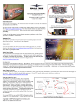
User Manual for the Seagull Wireless Dashboard Telemetry System
Patent Pending
Document Version 1.6, Model # ETS-SEA
READ ME FIRST!
Please read this manual before using your new system.
Thank you for your purchase! This instruction manual will guide you through the installation and operation of
your Seagull Wireless Dashboard Telemetry System. Please read the entire manual carefully before proceeding.
If, after you read the manual (including the Troubleshooting sections!) you have further questions or problems,
email us at [email protected] with your question. Note that the latest version of this manual is
available in PDF form from the Support page of our website.
Steps to Follow
Installation and use of your Seagull system will be quite easy and enjoyable if you follow these few steps:
1.
2.
3.
4.
Read through the manual to understand the warnings, determine the installation and setup sequence, etc.
Install the Data Recorder and Transmitter as described in Transmitter installation instructions below. Note that installing
your Data Recorder requires referring to the included Data Recorder manual, if you did not purchase your Recorder
separately.
Configure the Seagull system with your PC, as described the Seagull Configuration instructions below.
Bench and range test your model, and have fun!
FCC Information
Seagull Receiver FCC Information
Eagle Tree Systems
ETS-SEA
Tested to Comply With FCC Standards
FOR HOME OR OFFICE USE
FCC Radiation Exposure Statement Regarding the FCC Certified Seagull Transmitter (red case)
This equipment complies with FCC radiation exposure limits set forth for an uncontrolled environment. This equipment must be
operated with minimum distance of 20cm between the radiator and your body.
The Transmitter must not be co-located or operating in conjunction with any other antenna or transmitter.
FCC Caution
Any changes or modifications not expressly approved by the party responsible could void the user’s authority to operate this
equipment.
Copyright © 2004, 2005 Eagle Tree Systems, LLC
Page 2
Radio Interference and FCC Information
Note: This equipment has been tested and found to comply with the limits for a Class B digital device, pursuant to part 15 of the FCC
Rules. These limits are designed to provide reasonable protection against harmful interference in a residential installation. This
equipment generates, uses and can radiate radio frequency energy and, if not installed and used in accordance with the instructions,
may cause harmful interference to radio communications. However, there is no guarantee that interference will not occur in a
particular installation.
If this equipment does cause harmful interference to radio or television reception, which can be determined by turning the equipment
off and on,
the user is encouraged to try to correct the interference by one or more of the following measures:
--Reorient or relocate the receiving antenna.
--Increase the separation between the equipment and receiver.
--Connect the equipment into an outlet on a circuit different from that to which the receiver is connected.
--Consult the dealer or an experienced radio/TV technician for help.
Important Warnings
•
Make sure you have the right transmitter for your area. If the transmitter included has a red colored
case, it is FCC approved for US use. Using it outside the US may require a license or may not be
legal. If the transmitter has a gold case, it is designed for EU operation, and may not be legal
elsewhere. You are responsible for determining whether you may use your transmitter in your
country! See the transmitter specifications below for information on frequency and power output.
•
It is very important that you range check your model per your radio manufacturer’s instructions
after installing or reconfiguring any electronic equipment, and generally before each operation. If
you have range issues, see the Troubleshooting section, or email [email protected].
•
The Seagull system is to be used only as described in the “Intended Uses” section below. Other uses
are not supported, and uses where loss of life or injury may result are expressly forbidden.
•
Operating your model requires that you keep your eyes on it and give it your full attention. Looking
at the Seagull LCD display while the model is in operation is strongly discouraged. Use the
programmable audible alarms, or have a buddy look at the display, as necessary.
•
The Seagull Transmitter and Dashboard Receiver antennas are very flexible, but use care that you
don’t mount them in such a way that they could cause eye or other bodily contact injury.
Intended Uses and Additional Hardware Requirements
The Seagull System is designed to be used to transmit data in Radio Controlled model Planes, Cars, Helicopters, Boats and other RC
models. A Flight V2, Car or Boat Data Acquisition Module (Recorder) is also required for operation. Recorder Firmware Revision
2.16 or greater is required for Seagull operation. Connect your Recorder to USB and select “Help, About Data Recorder” in the
Windows Recorder Application (the App) to determine what firmware revision you have. Email [email protected] for
firmware upgrade information. Seagull is not compatible with the Flight Data Recorder V1.
Packing List
Your Seagull system includes the Wireless Telemetry Data Dashboard Receiver, the Wireless Telemetry transmitter, and this
instruction manual. If you ordered a full package system, the items listed in your Recorder manual are also included.
Copyright © 2004, 2005 Eagle Tree Systems, LLC
Page 3
Seagull Transmitter Installation Instructions
Install your Data Acquisition Module (Recorder)
If you have not already done so, install your Flight V2, Car or Boat Data Acquisition Module (Recorder) and desired accessories in
your model, following the included Recorder instructions. You may want to become familiar with the operation of your recorder and
the Windows application before installing the Seagull Transmitter, but this is not required.
Install the Seagull Transmitter in your Model
Choose a location in your model to install the transmitter. The transmitter is normally mounted with Velcro or double sided tape.
Ideally, the transmitter will be installed with its antenna and body as far away from your radio receiver (RX) as possible, with the
antenna protruding at right angles with your RX antenna, to reduce the possibility of interference. For example, if you have a model
plane with the receiver mounted horizontally along the plane’s fuselage, mount the Seagull so that the antenna is protruding from the
model vertically, as far forward of the RX antenna as possible. With a model car, the Seagull antenna can be mounted so that it
extends out of the side or front of the car, away and at right angles from the RX antenna.
Connecting the FCC Approved 900 MHz Seagull Transmitter to your Data Recorder
NOTE: If you have the 433 MHz EU transmitter, skip to the EU transmitter section below.
Plug the Seagull Transmitter cable into the “Expansion” port on your Recorder, as shown in Figure 1. Ensure that the Recorder is not
powered, and ensure that the red wire of the cable corresponds with the red dot on the port label (to the right of the connector).
Copyright © 2004, 2005 Eagle Tree Systems, LLC
Page 4
Connecting the EU 433 MHz Seagull Transmitter to your Data Recorder
NOTE: If you have the FCC approved 900 MHz transmitter, skip this step.
Plug the Seagull EU Transmitter cable into the “Expansion” port on your Recorder, into the bottom row of pins, as shown in Figure
1A. Ensure that the Recorder is not powered, and ensure that the red wire of the cable corresponds with the red dot on the port label
(to the right of the connector).
Seagull Dashboard Receiver Instructions
The Seagull Dashboard Receiver (the Dashboard) operates from a standard 9V battery. The battery installs in the back snap-off
compartment of the Dashboard. Approximately 12-14 hours continuous use is typical with an alkaline battery. Rechargeable 9V
batteries will work, but the run time will be significantly reduced.
Note: If the Dashboard will be unused for long periods, it is a good idea to remove the battery
Note: When removing the battery clip, use your thumb to pop the clip off from the side without the wires. Pushing on the wire side
can break the battery clip or the wires.
Refer to Figure 3, which illustrates the front of the Dashboard:
USB Connection: The USB cable supplied with your Recorder connects to the Dashboard
at this port. Note that the RED wire of the USB cable goes up, as shown by the red dot
above “USB” on the Dashboard label.
LCD Display: The 16 x 2 LCD character display is easily programmed to display up to
four model parameters per screen page.
Display Contrast: if the display contrast is not to your liking, remove the battery plate,
and carefully turn the blue potentiometer next to the battery compartment until the contrast
is better.
Pushbutton 1 (up arrow):
page.
The leftmost pushbutton advances to the next LCD screen
Figure 3
Pushbutton 2 (down arrow): This pushbutton returns to the previous LCD screen page.
Pushbutton 3 (Disp/Reset Max): pressing this pushbutton briefly causes the Dashboard to toggle between Max and Live modes. In
Max Mode, the parameters displayed have a carat (^) next to them to indicate they are the max parameters recorded. Note that some
parameters are not captured in Max Mode – these are displayed with “***”. Figure 6 shows which parameters have the Max feature.
In Live Mode, the data displayed are the live values received from the Transmitter.
Holding down this pushbutton for approximately two seconds zeros the Max parameters.
Copyright © 2004, 2005 Eagle Tree Systems, LLC
Page 5
Pushbutton 4 (Mute/Power): When the unit is in operation, pressing this button mutes or unmutes the audio portion of
the Dashboard, as well as turning off power. What happens when the mute button is pressed briefly depends on the state of the audio
system:
• If the audio is unmuted, and no alarm beeps are in progress, pushing the button causes the Dashboard to go into “Mute All”
state. No beeps will be heard in this state.
• If the audio is in “Mute All” state, pushing the button causes the Dashboard to go into “Unmute” state. All beeps will be
heard in this state.
• If the audio is unmuted, and alarm beeps are in progress, the Dashboard will go into “Mute Current” state. This state mutes
only the currently sounding alarm to be muted. All other beeps will be heard, and the currently sounding alarm will be heard
once the alarm condition occurs again.
When the Mute/Power button is held for approximately 2 seconds, the Dashboard is powered off.
Note: Pressing any of the keys when the power is off powers up the Dashboard.
Note: The Dashboard will power off after approximately 5 minutes when no signal is being received, and no buttons are pressed.
Seagull Configuration Instructions
Setting Metric or English Units
Metric or English units are selected via the Windows Recorder Application (the App). The default setting is English units. To
change this, Click “Tools, Choose What to Display” in the app, and click on “Display In Metric.” This causes both the App display
and the Seagull LCD display to switch to metric.
NOTE: whenever you change this parameter, you must re-download data to the Seagull Dashboard, as described
in “Seagull Dashboard Data Setup Utility Instructions” below.
Seagull Configuration Wizard
Ensure you have App version 2.0 or higher. Click “Help, About” in the App to determine what application revision you have.
Upgrade your application from our support web page if you do not have the latest version.
To configure the Seagull system, plug the USB cable into your PC and the Data Recorder, and launch the App and select “Tools,
Seagull Setup Wizard.” This wizard will guide you through the rest of the installation process. See the below instructions on
configuring specific items in the Wizard:
Seagull Transmitter Type: Select either the FCC US Transmitter (red case) or the EU transmitter (gold case) depending on which
system you have.
Seagull ID: The Wizard automatically generates an ID for your Seagull system, which you can change in the wizard. The Seagull
ID uniquely attaches your Seagull Transmitter to your Dashboard. This attachment means that it is unlikely that other Seagull
systems at your site will interfere with your system, and it also keeps your data private to some degree. Note that the Seagull system
will not operate if the Seagull Transmitter and Dashboard are set to different ID’s.
Note: The Dashboard ID is displayed in Hexadecimal in the lower right-hand side of the LCD screen at Dashboard power up.
Set Beep on Seagull Keyboard Press: Check this wizard box if you want a short beep to sound on each press of the Dashboard
buttons. Note that in this mode, selecting Mute All will silence these beeps.
Seagull Power Level (FCC transmitter only): The Seagull Transmitter supports operation at low (around 8-12 milliwatt) and high
(around 200 milliwatt) power levels. Normally low power is good for indoor use, and high power may be required for outdoor use.
Warning: Always range check your model after changing power levels!
Connecting the Dashboard to USB: When the Wizard asks you to Connect the Seagull Dashboard, disconnect the Recorder from
the USB connection, and connect the Dashboard as described in the “Seagull Dashboard Receiver Instructions” section above. Note:
Follow the Wizard instructions carefully – if the computer needs to reboot the first time the Dashboard is installed, do so and relaunch
the Wizard after reboot.
After the Dashboard is successfully discovered by your PC, “USB Mode Active” should display on the LCD window. If this does not
happen, see the Troubleshooting section below.
Copyright © 2004, 2005 Eagle Tree Systems, LLC
Page 6
Launching the Dashboard Data Setup Utility: After the Dashboard is discovered by the PC, the Next button of the
Wizard should ungray, and hitting Next take you to the final page of the Wizard. This page has a button to launch the Dashboard
Data Setup Utility. See the below section on running this utility. Once the utility is successfully run, the Finish button of the Wizard
will ungray.
Seagull Dashboard Data Setup Utility Instructions
This utility (the Utility) will appear the first time you run the Seagull Configuration Wizard, and can be re-run by selecting “Tools,
Edit Seagull Display” in the App. This utility is the tool used to bring your Seagull Dashboard to life – it gives you the capability of
configuring all of the items displayed on the LCD screen, setting up alarms, and configuring the Climbrate Alarm settings (Flight
Systems).
Figure 4 shows the main page of the Utility.
The Utility main page is divided into the following section:
Select Data Parameter to Configure on the Dashboard LCD: This section contains the tools to select what, how and where
parameters are displayed on the LCD pages.
Figure 6 provides a table of the parameters that can be configured with your system.
To select and configure a parameter, choose the parameter to be configured in the “Select Feature to Display” window. A “o” next to
an item indicates that this item is already selected for display, and choosing it will allow you to edit the item. After selecting the
parameter, click the “Enable this parameter…” checkbox to enable the parameter to be displayed/configured, or uncheck it to remove
it from the list.
Once the parameter is enabled, choose where the parameter will be displayed by choosing the location in the “Select Display
Location” window. A “o” next to the location chosen means it is already in use by this or another parameter. Choosing a location
that is in use already will cause the parameter using it to be disabled.
The window labeled “Enter the label to display..” in this section displays the 3 digit label that will be displayed beside this parameter
on the LCD. You can change this 3 digit label to be whatever you want. For example, if Temperature Sensor 1 was attached to your
Cylinder Head, you might label this parameter “CHT.”
NOTE: If the data for each parameter grows large, such as a large RPM, the middle character in the 3 digit label will be eliminated to
show all the numeric digits in the parameter. For example, “RPM 0” would become “RM 40342” in this case.
Set up alarms (if any) to be triggered by values of the above parameter: This section contains the tools to set up audible and
visual alarms for many of the displayed parameters.
NOTE: See the “Servo” section below for information on Servo setup.
NOTE: If you have a Flight System and select Climbrate, see the “Configuring Climbrate Alarms” section below.
To enable a “High Alarm” for a parameter, meaning that the alarm should activate if the parameter exceeds the set value, check the
High Alarm Enabled button.
To enable a “Low Alarm” for a parameter, meaning that the alarm should activate if the parameter falls below the set value, check the
High Alarm Enabled button.
NOTE: only a high or a low alarm can be configured for each parameter (not both).
To enter the alarm value, type the high or low threshold in the “Enter the Alarm Trigger Value” window. For values, such as RX
voltage, with a decimal place, enter the fractional part in the box to the right of the decimal point. For example, to set an alarm if
your RX voltage drops below 4.8 volts, enter 4 and 8 in the two boxes.
See the Parameter table in Figure 6 for high and low alarm limits. NOTE: when an alarm is triggered, a “!” appears to the right of the
parameter label on the LCD, to indicate the parameter is in an alarm state.
If you wish to have an audible beep sound when the alarm is triggered, configure the beep alarm as follows:
•
•
•
Select the number of beeps to sound in the “Number of Beeps” window.
Select the beep length in the “Length of each Beep” window.
Select the length of the “silence” between each of the beeps in the “Length of silent pause between beeps” window.
Copyright © 2004, 2005 Eagle Tree Systems, LLC
Page 7
If you wish the beeps to repeatedly sound when the alarm condition occurs, click on the “Check here to cause the alarm
beeps to sound continuously…” checkbox. If you wish the alarm to only sound once when the condition occurs, uncheck this box.
Note that when the alarm condition goes away, and then recurs, the alarm will sound again in both these cases. See the muting
section in the “Seagull Dashboard Receiver Instructions” above for information on muting the alarms.
If you want to have the Dashboard switch to the LCD page that has the alarming parameter, check the “Check here to automatically
Switch…” checkbox.
NOTE: If two or more alarm conditions occur simultaneously, only the last occurring condition will be signaled. If the last
condition to trigger an alarm goes away, the second to last currently active condition will be signaled, etc.
Once all the parameters you wish to display are configured, you can review the parameters by clicking the Preview button as shown in
Figure 5. The Preview window is a handy way to see which parameters are configured on which LCD page locations. A “***” in a
page location indicates that no parameter is displayed in that location.
Once the parameters are configured to your satisfaction, click OK, which will download the settings to the Dashboard. Note that you
can change the parameters at any time by following the above steps.
Note: If you wish to clear all previously configured parameters, hit the Clear button on the bottom of the utility.
Figure 4
Figure 5
Configuring Climbrate Alarms
If you have a Flight Data System, and wish to set up climbrate and/or sinkrate alarms for variometer support, click the Climbrate
button in the alarms section. Note that the Climbrate button will only appear when the Climbrate parameter is selected and Enabled.
Note also that when the Climbrate parameter is enabled, the Configure Climbrate Alarms page will automatically appear.
Carefully read the instructions on the Configure Climbrate Alarms page. This page should be self explanatory. The audible
climbrate/sinkrate alarms are configured in basically the same way that other alarm parameters are configured. One difference is that
both climbrate and sinkrate alarms can be simultaneously programmed.
Note that the altitude value displayed (if the altitude parameter is selected for display) is by default averaged and updated once during
each climbrate measurement time interval. If you wish to display the raw, unaveraged altitude value, uncheck this box. Note that the
altitude may “jump around” a bit if raw mode is chosen.
Servo Display on the Dashboard
Copyright © 2004, 2005 Eagle Tree Systems, LLC
Page 8
If you calibrated your servo movements with the App during Recorder setup, the Seagull should display the correct
names of your servos, i.e., “Ailerons.” If you did not calibrate, servos will be labeled “Servo 1”, etc.
If you calibrated, the data values displayed for your servos should be as follows:
Flight Systems: Rudder, Ailerons, Elevator: -100 to 100; Throttle: 0 to 100 (with negative values for idle trim down)
Car/Boat Systems: Throttle; centered at 0, max throttle 100, negative throttle negative; Steering; -100 to 100
Using your Seagull
Now that you have completed installation and configuration of the Seagull system, it’s time to actually use it!
First, ensure that you have disconnected the USB cable from the system. Power on your model as you normally would, turning on
your radio transmitter before powering up the model. The Recorder’s LED should blink normally (one flash repeating) after
powering up the model.
Next, power on your Dashboard. Since the Dashboard calibrates several of the parameters on powerup, always turn on your model
first, then turn on your Dashboard (or turn the Dashboard power off and on after you model is turned on).
At this point, the Dashboard should display live data, starting with Page 1 of the parameters you selected. If the Dashboard displays
“No Signal”, consult the Troubleshooting section below.
If you have the Flight System, please note the following on altitude and airspeed: Depending on your radio transmitter and model
wiring, having the transmitter close to the model with the antenna extended may cause the altitude and airspeed values to vary. If this
variation is happening when the Dashboard is turned on, altitude and airspeed may not zero properly. If you notice this problem, you
can either keep your radio transmitter antenna down when powering up the Dashboard (don’t forget to raise it before flying!!), or you
can simply power off and on the Dashboard after taxiing the model several feet away.
Once the Seagull system is communicating, consider how you will mount and use the Dashboard. The Dashboard can be mounted
to your radio transmitter with strips of Velcro so that you can hear the audible alarms, or handed to your crew or buddy to monitor
your run. It is a very bad idea to take your eyes off your model during operation!
DON’T FORGET TO RANGE CHECK YOUR MODEL AFTER INSTALLATION, AS DESCRIBED IN YOUR RADIO
MANUAL!
Using your Seagull in Laptop Live Mode
If you have a laptop at your site, or wish to see live data with your model on the bench, the App can be used to view the Seagull data
parameters live in a “big screen” format, with almost infinite recording capability!
To use Live Mode, first select “Tools, Choose What to Display” in the App, and set up the parameters you want to display.
Seagull specific items are available to display, as well as the other parameters:
Two
Seagull Signal Strength – this item shows the strength of the real-time signal coming from the Seagull Transmitter.
Seagull Packet Percent – this item shows the percentage of packets that were successfully received from Seagull.
To invoke Live Mode, first ensure that your Dashboard is receiving data from the transmitter. Then, connect the Dashboard to USB,
and click the Live Mode button on the App. A window may display asking you whether to record the Live Mode data. After
choosing this option, Live Mode should start and display the live parameters.
Note: several of the Live Mode parameters are zeroed when Live Mode is started. Stop and restart Live Mode if the parameters did
not correctly zero.
Note: whenever a packet is missed, the previous packet is duplicated in the Live Mode recording. The duplicated packets are marked
as duplicated in the “error” fields of the recording – these are visible when viewed in Excel. See the Recorder manual for more
information on viewing the files in Excel.
Copyright © 2004, 2005 Eagle Tree Systems, LLC
Page 9
Note: if the 9 volt battery is installed in the Dashboard, the Dashboard will be powered by the battery even when the
USB plug is connected. If you wish to monitor or record very long runs with Live Mode, turn off all power to the Dashboard and
remove the 9 volt battery. Then, the Dashboard will be powered by USB.
Troubleshooting
If your problem is not resolved after carefully reading the following section, email us at [email protected] for help.
Issue: I get the “No Signal” message from the Dashboard, and never see live data.
Solution: Make sure the Seagull ID is correctly set in both the Recorder and the Dashboard, by running through the Seagull Setup
Wizard.
Solution: Make sure the Seagull Transmitter is plugged into the correct Recorder slot, and that the plug polarity is correct. Note that
the Car and Flight/Boat systems require a different connection and polarity.
Solution: Make sure that the Recorder light is flashing one repeated flash (or two repeated flashes if the Recorder button is full)
Solution: Make sure that the Recorder is not connected to USB.
Solution: Turn model’s power off and on, then turn your Dashboard off and on.
Solution: Make sure you have chosen a Recorder sampling rate that is Seagull compatible. This is set in the App by choosing
“Tools, Choose Capture Rate” with the Recorder connected.
Issue: My Dashboard is receiving data, but it doesn’t look like correct data.
Solution: First, refer to your Recorder manual and read the section pertaining to the incorrectly displaying parameters. Then, verify
that parameters are working correctly with just the Recorder by either making a recording and playing it back, or using Recorder (not
Dashboard) Live Mode.
Solution: Some parameters, like altitude, airspeed and current, are “zero calibrated” each time the Dashboard is turned on. If these
parameters are not zeroed, try turning off and on the Dashboard.
Issue: My altitude or airspeed values seem to drift, even when the model is sitting still
Solution: Your radio transmitter puts out powerful radio signals, which may interfere with the operation of the altimeter or airspeed
sensor when close to your model. See the information in the “Using your Seagull in Dashboard Standalone Mode” section.
Solution: Some slight drift may occur after flying. Note that for airspeed, which is related to the square of pressure, slight drift from
zero will not affect your higher speed readings much. For example, if your Dashboard is displaying 9 MPH when not moving, the
error at 50 MPH would be closer to 1 MPH, rather than 9 MPH.
Issue: I am unable to successfully complete an antenna down range check with the Seagull Transmitter running.
Solution: Read the troubleshooting section in the Recorder manual and see if one or more of those solutions resolve the problem.
Solution: Try low power mode if you are not using it.
Solution: Try placing a snap-on choke on the cable between the Recorder and the Seagull Transmitter. Or, wind this cable four or
five turns through a toroid core.
Solution: Try operating the Recorder/Transmitter without any Y cables connected to your radio RX. This will require a small
battery to power the Recorder.
Issue: My Dashboard display is hard to read, or very dim.
Solution: See the “Display Contrast” information in the Seagull Dashboard section above.
Solution: Replace the Dashboard battery.
Issue: My Dashboard works briefly, then shuts off.
Solution: Replace the Dashboard battery.
Issue: I get periodic “No Signal” messages on the Dashboard during model operation
Solution: if you are operating at low power mode, try high power mode. Make sure you range check after changing power modes!
Solution: If others are operating Seagull systems in your area, try a different Seagull ID
Seagull Specifications
FCC Transmitter
Frequency Range:
FCC Approval:
Maximum Output Power:
Dimensions:
Weight:
Copyright © 2004, 2005 Eagle Tree Systems, LLC
902 – 928 MHz
15.247 Frequency Hopping Spread Spectrum
approx 200 mWatt
approx 2-3/4” x 1-1/4” x ¼”
approx 0.5 oz (Transmitter only)
Page 10
Temperature Range:
TX Antenna:
Power:
Current Draw:
0 – 140 degrees F
Thin, flexible stainless whip
Power taken from Recorder/Receiver battery
Transmitter + Recorder, average < 70 milliamp
EU Transmitter
Frequency Range:
Manufacturer:
Maximum Output Power:
Dimensions:
Weight:
Temperature Range:
TX Antenna:
Power:
Current Draw:
433 – 434 MHz
LPRS, UK
approx 10 mWatt
approx 38 x 14 x 4mm
approx 4 grams (Transmitter only)
-40 to 85 degrees C
Thin, flexible stainless whip
Power taken from Recorder/Receiver battery
Transmitter + Recorder, average < 60 milliamp
Receiver
Sensitivity:
RX Antenna:
Temperature range:
Battery:
Display:
Pushbuttons:
Contrast Adjustment:
USB connection:
< -110 dBm nom
Thin, flexible stainless whip
0 – 140 degrees F
Standard 9V
16x2 character LCD
4
Potentiometer behind battery door
Yes
Limited Warranty
Eagle Tree Systems, LLC, warrants the Seagull System to be free from defects in materials and workmanship for a period of one (1) year from the
date of original purchase. This warranty is nontransferable. If your unit requires warranty service during this period, we will replace or repair it at
our option. Shipping cost to us is your responsibility.
To obtain warranty service, email us to request an RMA number. No returns will be accepted without this number.
This limited warranty does not cover:
•
•
The Software Application. See the Software license agreement for more information on Software restrictions.
Problems that result from:
o External causes such as accident, abuse, misuse, or problems with electrical power
o Servicing not authorized by us
o Usage that is not in accordance with product instructions
o Failure to follow the product instructions
THIS WARRANTY GIVES YOU SPECIFIC LEGAL RIGHTS, AND YOU MAY ALSO HAVE OTHER RIGHTS WHICH VARY FROM STATE
TO STATE (OR JURISDICTION TO JURISDICTION). OUR RESPONSIBILITY FOR MALFUNCITONS AND DEFECTS IN HARDWARE IS
LIMITED TO REPAIR AND REPLACEMENT AS SET FORTH IN THIS WARRANTY STATEMENT. ALL EXPRESS AND IMPLIED
WARRANTIES FOR THE PRODUCT, INCLUDING, BUT NOT LIMITED TO, ANY IMPLIED WARRANTIES AND CONDITIONS OF
MERCHANTABILITY AND FITNESS FOR A PARTICULAR PURPOSE, ARE LIMITED IN TIME TO THE TERM OF THE LIMITED
WARRANTY PERIOD AS DESCRIBED ABOVE. NO WARRANTIES, WHETHER EXPRESS OR IMPLIED, WILL APPLY AFTER THE
LIMITED WARRANTY PERIOD HAS EXPIRED. SOME STATES DO NOT ALLOW LIMITATIONS ON HOW LONG AN IMPLIED
WARRANTY LASTS, SO THIS LIMITATION MAY NOT APPLY TO YOU.
WE DO NOT ACCEPT LIABILITY BEYOND THE REMEDIES PROVIDED FOR IN THIS LIMITED WARRANTY OR FOR
CONSEQUENTIAL OR INCIDENTAL DAMAGES, INCLUDING, WITHOUT LIMITATION, ANY LIABILTY FOR THIRD-PARTY CLAIMS
AGAINST YOU FOR DAMAGES, FOR PRODUCTS NOT BEING AVAILABLE FOR USE, OR FOR LOST DATA OR LOST SOFTWARE.
OUR LIABILITY WILL BE NO MORE THAN THE AMOUNT YOU PAID FOR THE PRODUCT THAT IS THE SUBJECT OF A CLAIM. THIS
IS THE MAXIMUM AMOUNT FOR WHICH WE ARE RESPONSIBLE.
SOME STATES DO NOT ALLOW THE EXCLUSION OR LIMITATION OF INCIDENTAL OR CONSEQUENTIAL DAMAGES, SO THE
ABOVE LIMITATION OR EXCLUSION MAY NOT APPLY TO YOU.
Eagle Tree Systems, LLC
http://www.eagletreesystems.com
[email protected]
4957 Lakemont Blvd SE
Suite C-4 PMB 235
Bellevue, WA 98006
FAX 425-484-4131
Copyright © 2004, 2005 Eagle Tree Systems, LLC