1
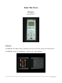
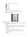
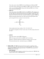
EMF - ITC
USER MANUAL
Version 1.00
by
Digital Dowsing, LLC.
www.DigitalDowsing.com
Copyright ©2006 -2013
TABLE OF CONTENTS
Disclaimers and Licensing..…………………………………………………………………………..3
Disclaimer of Liability, HTML Compatibility, Endorsement or Product Use……........................4
About EMF-ITC from the inventor ……....…………...……………………………………………...5
Safety……………………………………………………………………………………………………6
Intended Use……………………………………………………………...……………………………6
Theory of operation……………………………………………………………………………………6
About this device
Hardware……….……………………………………………………………………………....7
Operation……………………………………………………….……………………………....7
User Guide……………………………………………………………………………………………..8
Quality and service…………………………………………………………………………………..10
Returns………………………………………………………………………………………………..10
Help……………………………………………………………………………………………………10
2|Page
Disclaimers and Licensing
The EMF-ITC is sold as an entertainment device only. We make no claim to the validity
of the data received by this device.
As the owner of this device you are responsible for the device’s use. Further, you are
responsible for the safety of others who may come in contact with this device.
This device can generate disturbing text; children under the age of 18 should not use it.
Further, this device should not be used by anyone with a history of mental illness.
You agree not to expose children to this device, or any person who may be harmed or
damaged by exposure to this device. Further, you agree that you are over 18 and are in
sound mental condition.
3|Page
Disclaimer of Liability, HTML Compatibility, Endorsement or Product Use
WHILE EVERY EFFORT IS MADE TO ENSURE THE TIMELINESS AND ACCURACY OF THE INFORMATION,
DOCUMENTS, DATA, MATERIAL OR SOFTWARE (THE "INFORMATION") AVAILABLE ON Digitaldowsing.com IN
WRITTEN OR ELECTRONIC FORM, Digital Dowsing LLC. and CHAPP INC. ASSUMES NO LEGAL LIABILITY OR
RESPONSIBILITY FOR THE COMPLETENESS, ACCURACY OR USEFULNESS OF ANY OF THE INFORMATION
DISCLOSED. INFORMATION (INCLUDING ANY REVISIONS AND UPDATES) AND MATERIALS ARE PROVIDED SOLELY
FOR THE USER'S INFORMATION AND IS PROVIDED STRICTLY "AS IS." CHAPP INC. AND CHAPP.COM MAKE NO
REPRESENTATION OR WARRANTY, EXPRESS OR IMPLIED, IN RESPECT TO THE INFORMATION, SOFTWARE,
FIRMWARE OR HARDWARE EITHER ACCESSED VIA www.chapp.com or www.digitaldowsing.com THAT MAY BE
ACCESSED THROUGH THIS SITE BY WAY OF LINKS TO OTHER SITES, OR RECEIVED FROM CHAPP INC. OR ITS
AGENTS INCLUDING AND WITHOUT LIMITATION, AS TO:
a.
THE ACCURACY, ADEQUACY, COMPLETENESS OR RELIABILITY OF ANY INFORMATION HOWSOEVER
STORED OR TRANSMITTED, WHICH MAY BE OBTAINED BY ANY PERSON OR ANY ENTITY HAVING ACCESS
TO THIS SITE;
OR
b.
THE MERCHANTABILITY OR FITNESS FOR A PARTICULAR PURPOSE OR USE WITH RESPECT TO ANY
INFORMATION WHATSOEVER INCLUDED IN THIS SITE OR THAT MAY BE ACCESSED THROUGH THIS SITE;
OR
c.
THE RESULTS TO BE OBTAINED FROM USING SUCH INFORMATION.
USERS SHOULD ALSO NOTE THAT THE CHAPP INC. AND Digital Dowsing LLC, DO NOT ASSUME ANY
RESPONSIBILITY FOR THE QUALITY OF PRODUCTS OR SERVICES LISTED OR DESCRIBED IN THIS MANUAL. NOR
DO WE ENSURE COMPATIBILITY WITH PAST, CURRENT OR FUTURE VERSIONS OF SOFTWARE OR HARDWARE.
CHAPP INC. AND DIGITAL DOWSING LLC ASSUME NO RESPONSIBILITY FOR ANY DISCREPANCIES THAT MAY HAVE
BEEN TRANSMITTED WITH THE PRINTED OR ELECTRONIC VERSION OF THIS MANUAL, CONTROLLER OR
SOFTWARE.
WHILE EVERY EFFORT IS MADE TO ENSURE THE ACCURACY OF ALL INFORMATION PROVIDED IN THIS MANUAL,
AND THAT SOFTWARE DOES NOT CONTAIN COMPUTER VIRUSES, THE USER SHOULD TAKE REASONABLE AND
APPROPRIATE PRECAUTIONS TO SCAN FOR COMPUTER VIRUSES AND SHOULD ENSURE A COMPLETE AND
CURRENT BACKUP OF THE APPLICABLE ITEMS OF INFORMATION CONTAINED ON THE USER’S COMPUTER SYSTEM.
THE USER SHOULD PAY SPECIFIC ATTENTION TO SOME OF THE NEWER VIRUSES THAT HAVE BEEN WRITTEN TO
AUTOMATICALLY EXECUTE WHEN AN INFECTED DOCUMENT IS LOADED INTO CERTAIN WORD PROCESSING
PROGRAMS.
LINKS TO DIGITAL DOWSING AND CHAPP.COM ARE PROVIDED SOLELY FOR THE CONVENIENCE OF THE USERS
AND DO NOT CONSTITUTE AN ENDORSEMENT OF THOSE PARTIES OR ANY REPRESENTATION AS TO THE
ACCURACY, COMPLETENESS OR USEFULNESS OF THE INFORMATION SUPPLIED BY THEM. CHAPP INC. AND
CHAPP.COM ASSUME NO RESPONSIBILITY FOR ACTS, ERRORS, OR OMISSIONS BY OFF-SITE PARTIES OR THE
INFORMATION OR MATERIALS SUPPLIED BY THEM.
THE OWNERS OF CHAPP INC., CHAPP.COM, DIGITAL DOWSING LLC, DIGITALDOWSING.COM OR ITS AGENTS,
EMPLOYEES AND CONTRACTORS WILL NOT BE LIABLE TO ANY PERSON OR ENTITY HAVING ACCESS TO THIS
SOFTWARE, WEBSITES OR HARDWARE FOR ANY DAMAGES OF ANY KIND WHETHER DIRECT, INDIRECT, SPECIAL,
INCIDENTAL OR CONSEQUENTIAL, OR LOST PROFITS OR DATA, OR HARM TO PERSONS (INCLUDING DEATH),
HOWSOEVER CAUSED, WHETHER ARISING OUT OF NEGLIGENCE OR OTHERWISE, WHICH MAY BE OCCASIONED
FROM THE USE OF THIS SOFTWARE, HARDWARE, FIRMWARE OR WEBSITE INFORMATION OR THE POSSIBILITY
HEREOF.
BY USING THIS CONTROLLER OR INSTALLING THIS SOFTWARE, YOU ARE AGREEING TO BE BOUND BY THE TERMS
AND CONDITIONS SET OUT HEREIN AND ALL APPLICABLE LAWS AND REGULATIONS. IF YOU DO NOT AGREE WITH
ANY OF THESE TERMS, DO NOT USE THIS PRODUCT. RETURN IT FOR A FULL REFUND LESS SHIPPING COST.
4|Page
About The EMF-ITC device from the inventor
What is the EMF-ITC and why do we say for entertainment use only?
Let’s take this issue head on:
First and foremost the EMF-ITC is designed to aid in Paranormal Research.
The EMF-ITC uses what we call ECM or Environmental Communications Modes.
Some of our devices can create speech and text in this mode. So what is ECM? A method of taking
energy levels in the environment and creating speech…nothing more! We make no claim as to spirit
communications, aliens, ghosts or any other type of phenomena. Devices with this mode should be
considered “for entertainment.” Why? Because there’s no person who can prove to a certainty what
these messages are. Further, people need to take a rational, grounded approach to any device that
creates speech or text. The power of suggestion is very strong!
For the record, our devices do not use any type of random generator or sweep function. No algorithm
is employed to produce text or speech in a specific pattern.
Remember the odds of this device saying a word that is contextually correct is 1 in 2000
And in the units with phonetic speech the odds are only 1 in 71.
A lot of claims have been made about devices such as this. Simple math will tell you the odds are
much better than you think! That it’s just coincidence and nothing more.
Sincerely,
Digital Dowsing LLC
5|Page
Safety
NEVER allow children to operate this device!
Intended Use
1. These items are provided for adults over the age of 18 years.
2. This device is not intended for unsupervised use or unattended use.
3. It is for hobby or personal experimentation.
4. User has read and understands the Disclaimer and the manual before attempting any use of this
product or associated devices.
Theory of Operation
Let’s start with what the EMF-ITC does. The has 4 internal Antenna:
1. Channel A (+ Channel)
2. Channel B (- Channel)
3. Channel C (+ or - Channel)
4. Channel D (+ or - Channel)
The Ovilus samples Channels A, B & C,D returning a summed value. The values create ECM modes
input. (ECM, “Environmental Communications Modes”)
The software does not interrupt user input or make decisions beyond a basic limit filter. The only
functional mode of this device that speech is a simple 1 to 1 match of a level from the Channel input to
a word in the dictionary list.
The only filters are as follows:
1. Every sample an average is calculated. Each new value is compared to the average. If the
value is within the average plus or minus the “Offset,” the value is rejected.
2. The second filter is a repeat word buffer designed to prevent the same word from being
repeated.
So why filter? The unit senses the environment. If the energy levels are flat, “un-changing,” the unit
would simply repeat the same word over and over.
6|Page
About This Device
Hardware:
Your EMF-ITC is
Batteries:
The EMF-ITC has a Battery Door on the Back of the device. Slide this door open to install batteries.
The EMF-ITC requires 3 AAA Batteries. (Note the
+/-
when installing.)
7|Page
The EMF-ITC User Guide
About the EMF/ITC
We didn’t want to make another EMF meter ! there are already hundreds out there many are VERY good. We wanted to
make an EMF meter that was geared for Paranormal use. That’s why the LED scale can be changed or you can ignore EMF
below a certain level. This device has 5 different select screens just to display EMF so it can be tailored to the user or the
circumstances. We added ITC to allow users to experiment more ! Simply put nothing happens on demand. ITC takes time,
trial and error. That’s why we have added an Ovilus Mode to experiment with text driven purely by changes in the
environment. This device DOES NOT use any type of random generator ! The YES NO mode is an ITC approach for those
that want defined actions. The EMF level is sampled and a floating average is computed. In this Mode a – represents no
response, to get a YES the EMF must increase by the EMF percentage selected. To say NO the EMF must decrease below
the average by the same percentage creating a measured response ! EMF drawing mode is perhaps the strangest thing we
have ever done, Channels 3 and 4 are sample they are reacting to simple static electricity, EMF or Ionization. The Values
are drawn directly to the screen as pixels. Sometimes the images are simple lines or almost all dark or light other times
Numbers, letters figures ect. We started experimenting with this in the first beta versions of the Paranormal Puck, Though
we never released the drawing mode till this device was built.
Operating the EMF-ITC
1. The Power Switch is on the front of the EMF-ITC. To turn ON, slide the switch left. Slide it
right to turn OFF.
2. The EMF-ITC will display its Main Function Screen. The functions are listed below.
• EMF
This mode has several options from the EMF menu you can select how you want
the device to perform. Once selected the EMF option will appear on the main menu.
To return to the Main Function screen, press the ENTER button.
• OVILUS
The Ovilus will create words on the text screen one word per line. Up to six words
per run. Since this is a silent Ovilus it will wait before continuing after it has said the
chosen number of words. “See Ovilus Menu”
To return to the Main Function screen, press the ENTER button.
• YES NO
This mode will return YES NO or a dash based on EMF. The idea is very simple; if the
EMF increases by 10% the Word YES will appear. If the EMF decreases, the word NO
appears. The Minus bar will appear whenever the value is neither above nor below the
sample average. The percentage can be changed in the Ovilus menu.
To return to the Main Function screen, press the ENTER button.
• EMF DRAW
The device will “draw” across the screen, based on the amount of EMF present. When
the “draw” has filled up all 6 LED lines, the red light on the right side of the device will
illuminate. You can press the down/right arrow (button on the right side of the
faceplate) to allow the “draw” to continue, or press the ENTER button to go to the Main
Function Screen.
• DOWSING ROD
This mode is designed to act like Dowsing rods using inputs from the internal
8|Page
antennae’s. The Screen will display the following forms:
•
Straight
•
Left
•
Right
•
Widespread
•
Crossed
To return to the Main Function screen, press the ENTER button.
To change functions, press the up/left and down/right arrows on the front of the unit.
Press the ENTER button to select a function.
Function Sub-menus – press the down arrow and scroll through functions to access these sub-menus.
1. EMF – The EMF screen can be set to various types of EMF displays once select the display
type will become the default on the main screen.
• EMF ION
Choose this option to display for EMF and Ion count. The name EMF ION will display
in the main menu. ION detection is based on the difference between input channel A
and Input channel B. X = ABS(A-B)
• EMF SCOPE
Choose this option to display EMF with a scope function.
The Scope function Reads the EMF from the greatest magnitude of X,Y or Z
regardless of polarization. Then plots the changes in EMF as a wave form on the
lower section of the Screen.
• EMF BAR
9|Page
Choose this option to display EMF Bar Level and Minimum and Maximum EMF.
A bar will be shown depicting the current EMF level EMF is show in the upper portion
Of the screen, the Minimum EMF reading and the Maximum EMF reads are shown
above and below the bar Display.
• EMF XYZ
Choose this option to display EMF and all the Axis of EMF data. The small arrow on
the lower right of the screen will point to the area of the highest detected EMF. Please
note this is based on polarization of the field not just magnitude. All three axis will
display X,Y,Z in the lower left of the screen while the largest magnitude of EMF will
Display in the upper portion of the screen. The Arrow lower right will point to the
greatest magnitude based on polarity. See the chart below.
X+
Y+
YX-
So the quadrants break down as follows X+Y+, X-Y+,X+Y-,X-YIf at anytime the magnitude of X and Y are the same an X will be displayed instead of
the arrow.
• EMF HZ
Choose this option to display EMF and Frequency.
EMF on the upper portion of the Screen EMF on the Lower Portion
Frequency is displayed in Hz based on difference in channel 1 and 2 over time.
The measurement period has a maximum frequency of 10,000 Hz
2. EMF ALARM – The EMF alarm may be turned on to notify you of changes in the
following parameters. The alarm will notify you by flashing the LEDs. To turn ON the
alarm, press the ENTER and the right arrow button. To turn OFF the alarm, press the
ENTER and left arrow button.
• EMF MIN MAX
Pressing ENTER while this option is selected will zero out the value. MIN MAX only
displays when the unit is in EMF BAR mode.
10 | P a g e
• EMF ABOVE
Select this option if you want the alarm to notify you when EMF is above a certain
value. Increase the value by pressing ENTER until desired value appears.
To decrease depress the enter button then the left arrow button. The release the left
arrow then the enter button the count will decrease this will take a bit of practice but it’s
easy once you get the hang of it.
• EMF BELOW
Select this option if you want the alarm to notify you when EMF is below a certain
value. Decrease the value by pressing ENTER until desired value appears. (Once value
hits the maximum set by the factory, it will start again at 0)
To decrease depress the enter button then the left arrow button. The release the left
arrow then the enter button the count will decrease this will take a bit of practice but it’s
easy once you get the hang of it.
• EMF ZERO
In areas of normally higher EMF readings, this allows you to set the EMF sensor to
zero.
• LED SCALE
This allows you to change the sensitivity on the LED lights. The sensitivity will be
multiplied for each light, left to right, by the following scale:
1st = 1X, 2nd = 2X, 3rd = 4X, 4th = 8X, 5th = 16X, 6th = 32X
Increase the value by pressing ENTER until desired value appears.
To decrease depress the enter button then the left arrow button. The release the left
arrow then the enter button the count will decrease this will take a bit of practice but it’s
easy once you get the hang of it.
3. OVILUS • WORDS
This option will allow you to choose the number of words that will display on the
screen. (05 will show the maximum of 6 words) Press the ENTER button down to
change number of words. Once the screen has displayed the number of lines you have
chosen, the last red light on the right will illuminate. Press the down arrow button to
continue word display.
• OFFSET
The Offset is the difference between 2 channels. The device will favor one channel
over the other by changing the Offset. Press the ENTER button down to increase the
11 | P a g e
Offset. (Once value hits the maximum set by the factory, it will start again at 0)
• DD ROD
This option allows you to increase the sensitivity of the Dowsing Rods; the higher the
number, the greater the sensitivity. Press the ENTER button down to increase the
sensitivity. (Once value hits the maximum set by the factory, it will start again at 0)
• GAIN
This option allows you to increase the sensitivity of the Ovilus; the higher the number,
the greater the sensitivity. Press the ENTER button down to increase the sensitivity.
(Once value hits the maximum set by the factory, it will start again at 0)
• YN
This option allows you to change the percentage of the YES NO function. Press the
ENTER button down to change the percentage from 10% to 40%.
4. SYSTEM MENU – To change press the ENTER button until desired value is displayed.
•
HZ GAIN – This increases the sensitivity for the frequency counter circuit.
•
ION GAIN – This increases the Ion sensitivity.
•
ZERO EMF – Zero EMF will turn on and off the Zero EMF function
•
CAL SET – Set in factory only.
PLEASE DO NOT ATTEMPT TO MAKE CHANGES IN THIS MODE
“LOCKED OUT IN VERSION 1.06 AND ABOVE”
•
IMAGE – This increases the sensitivity for the EMF DRAW circuit.
The EMF Meter section is comprised of a 3 axis accelerometer, and microprocessor.
Sampling all three Axis continuously. EMF is always display as the greatest magnitude
of the three axis. Choose the EMF XYZ mode to display EMF plus X,Y,Z and direction
of field . This device is designed to allow the user to customize it. The LED’s can be set
so that the scale can be either compressed or expanded EMF levels can be suppressed by
using the zero function .
It may seem like a lot, but really it’s a simple system.
If you’re having trouble or just have questions PLEASE LET US KNOW!!
www.digitaldowsing.com
or Email
[email protected]
12 | P a g e
Quality and Service
Digital Dowsing LLC. has made every effort to provide a well designed and quality manufactured
product. Each EMF-ITC has been tested for function prior to shipping. This test checks inputs and
functions. We hope you find our products meet with your satisfaction.
Returns
If you have read this manual and decided that this device does not meet your needs for any reason:
•
•
•
•
We only accept unused returns for a refund within 7 days of purchase.
E-mail [email protected], in the Subject line state: “RMA requested”
Include a brief note stating that you would like to return the device.
We will E-mail instructions for its return and refund the amount of purchase, less
shipping charges.
Need Help?
E-mail us at [email protected]
• State the nature of your problem
• Please send picture or drawings if needed.
• Detailed information about the problem.
We try to respond in 24 hours or less, Monday – Friday 10am to 5pm.
13 | P a g e