1
The device bears the CE label in accordance with the provisions of Medical Device Directive
93/42/EEC.
THE PERSONS RESPONSIBLE FOR PLACING DEVICES ON THE EC MARKET UNDER
MDD 93/42/EEC
Jawon Medical Co.,Ltd.
29, Gongdan 4-ro, Jillyang-eup, Gyeongsan-si, Gyeongsangbuk-do, Korea
TEL: 82-53-856-0993, FAX: 82-53-856-0995
VITAKO Sp. z o.o.
UL. MALEJ SYRENKI 2 71-790 SZCZECIN, POLAND
TEL: 91 8522900 / 901, FAX: 91 8522910
-2-
TABLE OF CONTENTS
• INTRODUCTION.............................................................................................
4
1. IINTENDED USE...........................................................................................
4
2. WORD DEFINITIONS....................................................................................
4
3. CLASSIFICATION AND COMPLIANCE........................................................
5
4. SAFETY PRECAUTIONS..............................................................................
5
5. SAFETY SYMBOLS AND INFORMATION.....................................................
8
6. Guidance for Electromagnetic compatibility (EMC) .......................................
10
• TERMS OF EACH PART AND FUNCTIONS..............................................
15
1. FRONT PART.................................................................................................
15
2. PRINTER........................................................................................................
17
3. REAR PART....................................................................................................
18
4. ACCESSORIES..............................................................................................
20
5. OPTIONS.......................................................................................................
20
• INSTALLATION................................................................................................
21
1. CONNECTING ADAPTER.............................................................................
21
2. LOADING THE PRINT PAPER......................................................................
21
3. CONNECTING PORTS (RS-232C)................................................................
22
4. SETTING TIME AND DATE...........................................................................
23
• MEASUREMENT.............................................................................................
25
1. CAUTIONS FOR MEASUREMENT...............................................................
25
2. MEASUREMENT............................................................................................
26
3. DATA ON MEASUREMENT BY PRINTER.....................................................
29
• OPTION.............................................................................................................
• MAINTENANCE...............................................................................................
• ERROR&REPAIR.............................................................................................
• AFTER SERVICE.............................................................................................
31
1. AFTER SERVICE..........................................................................................
42
2. PACKING AND TRANSPORT........................................................................
42
• SPECIFICATION..............................................................................................
• WARRANTY.....................................................................................................
43
-3-
39
41
42
44
INTRODUCTION
We highly appreciate that you chose our company’s product.
You are kindly requested to be familiar with these directions before using this product and always keep it
together with the product. In case you are not sure about any directions or problems arising while using
the product, please contact our service center.
We will provide you with detailed instructions.
1. INTEDED USE
EASY X 800 (R/L) Automatic Blood Pressure Monitor is designed to measure systolic and diastolic blood
pressure and pulse rate of Persons who are 18 years and older using the oscillometric method on a
cuffed arm.
EASY X 800 L measure the Left arm.
EASY X 800 R measure the Right arm.
• Target user: Persons who are 18 years and older
• This medical device is not for home use
2. WORD DEFINITIONS
To ensure safe operation and long term performance stability, it is essential that you fully understand the
functions, operating and maintenance instructions by reading this manual before operating your unit.
Particular attention must be paid to all warnings, cautions and notes incorporated herein.
The following conventions are used throughout the manual to denote information of special emphasis.
Warning
Important information to indicate any possible hazard which can cause severe
personal injury of death from substantial property damage when ignored.
Caution
Important information to indicate any possible hazard which will or can cause minor
personal injury or property damage when ignored.
Note
Important information to notify to the user about installation, operation, or
maintenance information which is important but not hazardous. Warnings against
hazard are not to be included under the NOTE signal word.
-4-
3. CLASSIFICATION AND COMPLIANCE
1) This device is classified as;
- Class 1 type-BF against electric shock
- Ordinary equipment without protection against ingress of water
- Equipment not suitable for use in presence of a flammable anesthetic mixture by standard of EN
60601-1: 2006(Basic safety and essential performance of Medical Electrical Equipment)
2) This device is complied with Class A for Noise-Emission, Level B for Noise-immunity, by standard of
IEC 60601-1-2:2007(Electromagnetic Compatibility Requirements).
3) This device is complies with the EN 1060-1: 1995+A2:2009 Non-invasive Sphygmomanometers
general requirements as well as EN 1060-3: 1997+A2:2009 supplementary requirements for electromechanical blood pressure measuring systems.
4. SAFETY PRECAUTIONS
This device is designed and manufactured with consideration of safety of the operator and subject and
also to the reliability of the unit.
The following precautions must be observed for additional safety;
1) The unit must be operated only by, or under supervision of a qualified person with our company or
our distributors.
2) This device is specified as Class 1 type BF unit under the standard of IEC 60601-1:2005(Safety of
Medical Electrical Equipment).
Do not touch or handle inner side of the system at any time.
The INTERNAL ELECTRICAL POWER SOURCE is to be used if the integrity of the PROTECTIVE
EARTH CONDUCTOR or the protective earthing system in the installation is in doubt.
3) Do not modify the unit. If any modification is needed, ask our company or its authorized dealer for
service.
4) The unit has previously been adjusted in the factory for optimum performance.
Do not attempt to adjust switches or any other things except those specified in this manual for
operation.
5) If you have experienced any trouble with the unit, switch it off immediately, and contact our company
or its authorized dealer for assistance.
6) If you plan to connect any device of other manufacturers electrically or mechanically to the unit,
contact our company or its authorized dealer for instructions before doing so.
When you connect computer or other system to the unit (RS-232C), the attached systems should be
those certified by IEC 60950 or equivalent standards for data processing equipment.
Configurations shall comply with the system standard IEC 60601-1:2005.
Everybody who connects additional equipment to the signal input part or signal output part configures
a medical system standard IEC 60601-1:2005.
If in doubt, consult the A/S department of local distributor.
-5-
7) Avoid the following environments for storage;
- Where the ambient temperature falls -20°C or exceeds 60°C.
- Where the atmospheric pressure falls below 70kPa (700mbar) or exceeds 106kPa (1060mbar).
- Where the humidity is over 95% non-condensing.
- Where the unit is exposed to spray or splashing water.
- Where the unit is exposed to dust.
- Where the unit is exposed to water vapor.
- Where the unit is exposed to salty atmosphere.
- Where the unit is exposed to explosive gas.
- Where the unit is exposed to excessive shocks or vibrations.
- Where the angle of inclination of mounting surface exceeds 10 degrees.
- Where the unit is exposed to direct sunlight.
8) This equipment has been tested and found to comply with the limits for medical devices to the IEC
60601-1-2:2007. These limits are designed to provide reasonable protection against harmful
interference in a typical medical installation. This equipment generates uses and can radiate
radio frequency energy and, if not installed and used in accordance with the instructions, may
cause harmful interference to other devices in the vicinity. However, there is no guarantee that
interference will not occur in a particular installation. If this equipment does cause harmful
interference to other devices, which can be determined by turning the equipment off and on, the
user is encouraged to try to correct the interference by one or more of the following measures:
- Reorient or relocate the receiving device.
- Increase the separation between the equipment.
- Connect the equipment into an outlet on a circuit different from that to which the other device(s)
are connected.
- Consult the manufacturer or field service technician for help.
9) Do not to touch signal input, signal output or other connectors, and the patient simultaneously.
10) a statement that MEDICAL ELECTRICAL EQUIPMENT needs special precautions regarding
EMC and needs to be installed and put into service according to the EMC information provided
in the ACCOMPANYING DOCUMENTS;
11) a statement that portable and mobile RF communications equipment can affect MEDICAL
ELECTRICAL EQUIPMENT.
12) Please consult a physician or a trained health professional for interpretation of measurement
results.
13) No phthalates are used for this product and its container.
14) The cuff is not made with natural rubber latex
-6-
Caution
1. Measurements may be impaired if this device is used near televisions, microwave
ovens, X-ray equipment or other devices with strong electrical fields. To prevent
such interference, use the meter at a sufficient distance from such devices or turn
them off.
2. Incorrect operation or failure of user to maintain the unit spares the manufacturer
or his agent of the responsibility for system’s non-compliance with specifications or
responsibility for any damage or injury.
Caution
This manual is made for informational purpose and this manual and product are not
meant to be a substitute for the advice provided by your own physician or other
medical problem. You should not use the information contained in the product for
diagnosis or treatment of health problem or prescription of medication by yourself.
If you have or suspect that you have a medical problem, consult with your physician
promptly.
Defective unit or accessories must be packed in the replacement cartons to be
shipped off from you to our company.
Shipping and insurance costs for return of defective unit must be prepaid by the
users.
-7-
5. SAFETY SYMBOLS AND INFORMATION
The International Electrotechnical Commission (IEC) has established a set of symbols for medical
electrical equipment which classifies a connection or warning of any potential hazard.
The classifications and symbols are shown below. Save these instructions for your safety.
Degree of protection against electric shock: TYPE BF
Please observe operating instructions
General warning sign
General prohibition sign
General mandatory action sign
Caution
Waste Electrical and Electronic Equipment (WEEE)
The device could be sent back to the manufacturer for recycling or
proper disposal after their useful lives. Alternatively the device shall be
disposed in accordance with national laws after their useful lives.
"OFF" (only for a part of equipment)
"ON" (only for a part of equipment)
-8-
This symbol is used inside system.
Identifies the point where the safety ground of the system is fastened to
the chassis.
Do not open. This is for factory only.
Alternating current
Direct current
Date of manufacture
Manufacturer
Non-ionizing radiation
CE mark
Serial No.
Authorized representative in the European community.
Keep dry
RoHS2
-9-
6. Guidance for Electromagnetic compatibility (EMC)
Details about the electromagnetic compatibility (EMC) of the EASY X 800 are given below. Before using
the EASY X 800, be sure to read and understand the following information.
1) Guidance and manufacturer’s declaration – electromagnetic emissions
The EASY X 800 is intended for use in the electromagnetic environment specified below. The customer or
the user of the EASY X 800 should assure that it is used in such an environment.
Emissions test
Compliance
Electromagnetic environment – guidance
The EASY X 800 uses RF energy only for its internal
RF emissions
CISPR 11
function. Therefore, its RF emissions are very low and
Group 1
are not likely to cause any interference in nearby
electronic equipment.
RF emissions
CISPR 11
Class B
The EASY X 800 is suitable for use in all
Harmonic
emissions
establishments, including domestic establishments and
Class A
IEC 61000-3-2
those directly connected to the public low-voltage
Voltage
power supply network that supplies buildings used for
domestic purposes.
fluctuations/
flicker emissions
Compliance
IEC 61000-3-3
2) Guidance and manufacturer’s declaration – electromagnetic immunity
The EASY X 800 is intended for use in the electromagnetic environment specified below. The customer or
the user of the EASY X 800 should assure that it is used in such an environment.
Immunity test
60601
test
level
Compliance
Electromagnetic
level
guidance
environment-
Floors should be wood, concrete or
Electrostatic
discharge(ESD)
IEC 61000-4-2
Electrical
IEC
fast
±6kV: Contact
±6kV: Contact
ceramic tile. If floors are covered with
±8kV: Air
±8kV: Air
synthetic
material,
the
relative
humidity should be at least 30 %.
±2kV:
Power
±2kV:
Power
Mains power quality should be that of
transition/burst
supply lines
supply lines
a typical commercial or hospital
IEC 61000-4-4
±1kV:
±1kV:
environment.
- 10 -
Input/output lines
Input/output
lines
±1 kV differential
±1 kV differential
Surge
mode
mode
IEC 61000-4-5
±2
±2 kV common
kV common
mode
mode
Mains power quality should be that of
a typical commercial or hospital
environment.
<5 % UT
<5 % UT
(>95 % dip in
(>95 % dip in UT)
UT)
for 0,5 cycle
for 0,5 cycle
Mains power quality should be that of
40 % UT
40 % UT
a typical commercial or hospital
(60 % dip in UT)
(60 % dip in UT)
environment. If the user of the EASY
for 5 cycles
for 5 cycles
X 800 requires continued operation
70 % UT
70 % UT
during power mains interruptions, it is
supply line IEC
(30 % dip in UT)
(30 % dip in UT)
recommended that the EASY X 800
61000-4-11
for 25 cycles
for 25 cycles
be powered from an uninterruptible
<5 % UT
<5 % UT
power supply or a battery.
(>95 % dip in UT)
(>95 % dip in
for 5 sec
UT)
Voltage
drops,
dips,
and
fluctuations
input
of
power
for 5 sec
Magnetic field of
Power
commercial
frequency
3 A/m
frequency
magnetic fields
should be at levels characteristic of a
3 A/m
typical
(50/60Hz)
location
in
a
typical
commercial or hospital environment.
IEC 61000-4-8
Note
UT is the a.c. mains voltage prior to application of the test level.
- 11 -
3) Guidance and manufacturer’s declaration – electromagnetic immunity 2
The EASY X 800 is intended for use in the electromagnetic environment specified below. The customer or
the user of the EASY X 800 should assure that it is used in such an environment.
Immunity test
IEC 60601 test level
Compliance
level
Electromagnetic environment-guidance
Portable
and
mobile
RF
communications equipment should be
used no closer to any part of the EASY
X 800, including cables, than the
recommended
separation
distance
calculated from the equation applicable
to the frequency of the transmitter.
Recommended separation distance
d =1.2
Conducted RF
3 Vrms
IEC 61000-4-6
150 kHz to 80 MHz
Radiated RF
3 V/m
IEC 61000-4-3
80 MHz to 2,5 GHz
3 Vrms
3 V/m
d =1.2
80 MHz to 900 MHz
d =2.3
900 MHz to 2,5 GHz
where P is the maximum output power
rating of the transmitter in watts (W)
according
to
manufacturer
the
and
transmitter
d
is
the
recommended separation distance in
meters (m).
Field
strengths
from
fixed
RF
transmitters, as determined by an
electromagnetic site survey,a should be
less than the compliance level in each
frequency range.b
Interference may occur in the vicinity of
equipment marked with the following
symbol:
- 12 -
Caution
1. At 80 MHz and 900 MHz, the higher frequency range applies.
2 These guidelines may not apply in all situations. Electromagnetic propagation is
affected by absorption and reflection from structures, objects and people.
a
Field strengths from fixed transmitters, such as base stations for radio
(cellular/cordless) telephones and land mobile radios, amateur radio, AM and FM
radio broadcast and TV broadcast cannot be predicted theoretically with accuracy.
To assess the electromagnetic environment due to fixed RF transmitters, an
electromagnetic site survey should be considered. If the measured field strength in
the location in which the EASY X 800 is used exceeds the applicable RF
compliance level above, the EASY X 800 should be observed to verify normal
operation. If abnormal performance is observed, additional measures may be
necessary, such as reorienting or relocating the EASY X 800.
b
Over the frequency range 150 kHz to 80 MHz, field strengths should be less than 3
V/m.
4) Recommended separation distances between portable and mobile RF communications
equipment and the EASY X 800
The EASY X 800 is intended for use in an electromagnetic environment in which radiated RF disturbances
are controlled. The customer or the user of the EASY X 800 can help prevent electromagnetic
interference by maintaining a minimum distance between portable and mobile RF communications
equipment (transmitters) and the EASY X 800 as recommended below, according to the maximum output
power of the communications equipment.
Rated
maximum
Separation distance according to frequency of transmitter
output power
of transmitter
W
m
150 kHz to 80 MHz
80 MHz to 900 MHz
900 MHz to 2,5 GHz
d =1.2
d =1.2
d =1.2
0.01
0.12
0.12
0.23
0.1
0.38
0.38
0.73
1
1.2
1.2
2.3
10
3.8
3.8
7.3
100
12
12
23
For transmitters rated at a maximum output power not listed above, the recommended
separation distance d in meters (m) can be estimated using the equation applicable to the
- 13 -
frequency of the transmitter, where P is the maximum output power rating of the transmitter in
watts (W) according to the transmitter manufacturer.
Caution
1. At 80 MHz and 900 MHz, the separation distance for the higher frequency range
applies.
2. These guidelines may not apply in all situations. Electromagnetic propagation is
affected by absorption and reflection from structures, objects and people.
- 14 -
TERMS OF EACH PART AND FUNCTIONS
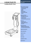
1. FRONT PART
① START BUTTON
Press START button after being ready to measure, the cuff will be wrapped automatically and begins to
pressurize.
② STOP BUTTON
Press STOP button if you want to stop it during measurement. Pressurizing will stop and the air will
exhaust from the cuff.
③ SYSTOLIC DISPLAY
It indicates systolic blood pressure values.
④ DIASTOLIC DISPLAY
It indicates diastolic blood pressure values.
⑤ PULSE DISPLAY
It indicates pulse rate.
⑥ TIMER
It indicates time.
⑦ EMERGENCY STOP BUTTON
When your arm is oppressed due to high pressurizing or irregular operation is done, press this button
then the cuff will be exhausted rapidly.
⑧ PRINTER COVER
It protects the printer.
⑨ AUTOMATIC CUTTER (printing paper let-out slot)
Printing paper is automatically cut off when it comes out through the slot.
⑩ CUFF
It wraps and releases the arm automatically for measurement.
⑪ ARM REST
When the arm is placed on the cuff, the arm supporter sustains the arm and makes the right position.
⑫ HUMAN SENSOR(option)
When a user approaches, power is automatically turned on and vice versa.
⑬ RFID CARD-READER(option)
When RFID card is applied, it reads information in it and stores the measured results.
⑭ MAGNETIC CARD-READER(option)
When magnetic card is swiped, it reads information in it and stores the measured results.
- 15 -
Note
The cuff and the buttons (START and STOP button) of this device are located at
reverse side by R and L type.
FRONT PART
④ DIASTOLIC DISPLAY
⑪ ARM REST
③ SYSTOLIC DISPLAY
⑥ TIMER
⑤ PULSE DISPLAY
⑬ RFID CARD-READER
⑩ CUFF
⑭ MAGNETIC CARD-READER
① START BUTTON
② STOP BUTTON
⑦ EMERGENCY
STOP BUTTON
⑨ PAPER OUTPUT
⑧ PRINTER COVER
⑫ HUMAN SENSOR
Note
Printer, card reader and human sensor are optional.
ID card can be issued either by the machine manager or by the manufacturer of the
model.
The card stores six previous measured results and can contain seven measured
results with the current one altogether.
When the model manager writes the card, please refer to the manual and
specifications for operation and programs attached to the card writing device at
purchase.
- 16 -
2. PRINTER
① PRINT button
- Use it when you print out the data.
- If you set [ON] at the rear (PRINT ON/OFF switch), the data is printed automatically even when you do
not press PRINT button.
- Normally, when you press this button, one previous data will be printed. (If you turn it off, all memorized
data would be deleted.)
- When you set the date and time, the number goes up with this button pressed.
② FEED button
- Use this button for setting the paper.
- When you set the date and time, the number goes down with this button pressed.
③ SET button
- Set the date and time.
- The functions are as follows when pressing this before or after measurement.
(It does not work during measurement)
- Sequence is HOUR → MIN. → MON. → DAY → YEAR
- If you do not press PRINT or FEED button within 5seconds, setting of the date and time finished.
- See the page ‘15’ for detailed method.
- 17 -
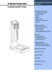
3. REAR PART
① POWER
It is used to turn the power on and off.
② POWER INPUT
It is used to connect with the adapter.
③ CAL
This is only for inspection. Never open it.
④ EARTH (POTENTIAL EQUALIZATION TERMINAL)
Please make sure for safety.
⑤ COMMUNICATION PORTS (RS-232C)
Connect between the main body and a computer or other equipment with cable (RS-232C) to transfer
the data collected or measured. Or connect between the main body and the coin slot with RS-232C
cable to transfer the data.
⑥ BACK MONITOR PORT(option)
Connect the main body to the reverse monitor cable.
⑦ USB PORT
Connect the main body and USB cable.
⑧ SENSOR ON/OFF
Human sensor is switched on and off.
⑨ SOUND ON/OFF
Music and voice output functions are activated with the switch [ON], and vice versa.
⑩ CARD ON/OFF
Card is usable when the switch [ON], and vice versa.
⑪ PRINT ON/OFF
Measured results are printed out when switched [ON], and vice versa.
⑫ VOLUME (ANNOUNCE ON/OFF)
It controls volume output when switch is on while all volume is [OFF].
⑬ REVERSE MONITOR(optional)
You can see the ID No, B.M.I., and Fatness as well as Blood Pressure on the reverse monitor.
⑭ INFORMATION BOARD FIXER
Fix the information board here.
- 18 -
Note
1. While sound switch is activated on (so sound is functioning), place the VOLUME
ON/OFF switch to [OFF] for deactivation of voice message and music play.
2. Printer, card reader, human sensor and reverse monitor is optional.
3. The operator should not touch both USB port and the patient’s body
simultaneously.
Note
The operator shall not contact the parts (SIP/SOP) and the patient simultaneously and
“SIP/SOP shall be available to operator only”
REAR PART
⑭ INFORMATION
BOARD FIXER
⑬ REVERSE
MONITOR
⑫ VOLUME
① POWER
⑤ COMMUNICATION
⑪ PRINT ON/OFF
PORTS
② POWER INPUT
⑥ BACK MONITOR
⑧ SENSOR ON/OFF
PORT
⑨ SOUND ON/OFF
③ CAL
④ EARTH
⑦ USB PORT
- 19 -
⑩ CARD ON/OFF
4. ACCESSORIES
Adapter/Power cable
Manual
Guide
5. OPTIONS
Cart / Chair
RFID Card/Magnetic Card
Thermal paper / Printer
Human sensor
Reverse monitor
Reverse monitor support/cable
- 20 -
INSTALLATION
1. CONNECTION ADAPTER
Just connect the power cable to the adapter on the rear and turn the POWER ON/OFF switch on the
lower part of the rear (See the picture).
Caution
In order to avoid the risk of electrical shock, connect this device only to the power
supply equipped with the protective grounding.
Caution
When connecting adaptor, place the arrow mark of adaptor connection
part up and correctly stick it in the socket on the rear of the main body.
Wrong connection could be a fire hazard.
2. LOADING THE PRINT PAPER
①
Check and see if power is turned on.
②
Turn the nut (with a driver on the groove in the middle) on the lower printer cover clockwise to 90
degrees and open the cover.
③
Load the print paper as shown in the picture.
④
Insert the paper edge deep under the black roll, then it comes out above the CUTTER.
⑤
Balance the paper in the right place.
⑥
Cut the paper by pressing the FEED button.
⑦
Close the cover and turn the nut counterclockwise back.
- 21 -
Note
Being thermal type, printing is photocopied on one side of the paper (slippery side),
without using printing ink.
Please check remainder of the paper always and then replace it.
Please use exclusive paper (58mm).
Keep paper rolls in a dark and ventilated place.
Avoid any dust on the paper.
Do not pull the paper during printing. It could cause jam.
When printing paper is not loaded in correct place, it may cause the malfunction of the
printer or paper will be shoved out.
After the exchange of paper to the printer cover does not close properly, the alarm
sounds, LED on the 'Err' is displayed. Please check the status of the printer cover.
3. CONNECTING PORT (RS-232C)
To transmit the data, connect a computer or other external options to the unit.
Connect the RS-232C cable both to port of the unit and to the computer jack or other external options.
(See the picture)
- 22 -
4. SETTING TIME AND DATE
• Turn on the unit.
• Open the printer cover.
• Sequence is HOUR → MINUTE → MONTH → DAY → YEAR
HOUR
① Press SET button, then indicator will blink. At that time,
press PRINT button. Its counts that have been measured
since keeping button ON will be printed.
② Press SET button once again. First 2 figures will blink.
③ To set the current hour, press PRINT button to make the
number goes up or press FEED button to make the number
goes down.
MINUTE
① After setting the hour, press the SET button again.
② In this time, last 2 figures will blink.
③ As the same way as above, set the current minute with
PRINT and FEED button.
MONTH
① After setting the minute, press SET button again.
② First 2 figures will blink.
③ Set the current month with PRINT and FEED button.
DAY
① After setting the month, press SET button again.
② Last 2 figures will blink.
③ Set the current day with PRINT and FEED button.
YEAR
① After setting the day, press SET button again.
② First 2 figures will blink.
③ Set the current year with PRINT and FEED-button.
23 -
Note
If you want to measure blood pressure during setting the date and time, press STOP
button. Then you can measure again immediately.
Note
You should set all data at once (hour, minute, month, day and year).
In case of stopping setting, the values return to previous ones which you have done
before.
The calendar and time functions work without plugging power cord in.
Calendar program is inputted for 100 years, and it would be adjusted automatically
even at a leap year.
- 24 -
MEASUREMENT
1. CAUTIONS FOR MEASUREMENT
- 25 -
2. MEASUREMENT
①
Check the voltage and turn the power on.
② With the switch-on, a music sound flows as the LED
screen is activated.
But, the SOUND ON/OFF switch in the rear of the unit
should be set as 「ON」
③ For the card users, proceed with checking after
entering the card into the card-reader.
When the card is inserted, a voice message comes out to “Press the start button.”
Note
For ID card using, the CARD ON/OFF switch in the rear of the unit should be set as
「ON」.
If the card is damaged or expired, the voice message comes out as “Can not use ID
card.”
In this case, purchase new one and try again.
④ put either the right arm or left arm into the cuff.
Note
An optimal arm circumference for this equipment is 9” to 14”.
- 26 -
Caution
Place your arm on the arm supporter with
the palm facing up through the cuff deeply.
Adjust the height of the chair so that the arm
is leveled off with the heart.
When the arm is placed lower than the
heart, blood pressure will become higher
than actual value, and vice versa.
⑤
Press the START button and then the cuff is automatically inflated
and the measurement is stated.
Caution
When the measurement is started, the voice
message
is
announced
as
“Starting
measurement, don’t move or speak please.”
When you feel painful and want to stop the
measurement,
press
EMERGENCY
BUTTON.
⑥
When the measurement completed, the cuff is automatically deflated and it returns to normal condition.
Simultaneously, the voice message is announced as “Measurement completed, pull your arm out
please. Thank you.”
Note
When the measurement is not satisfactory, the voice message comes out as “Cannot
measure, we will try again.” At this time, let your arm stay into the cuff and start over
again from the beginning.
- 27 -
⑦
Blood pressure and pulse rate are displayed on LED and then the
results are printed out. Also the results are informed by the voice
message as “Your blood pressure is systolic 000, diastolic 000 and
pulse 000.”
⑧
Pull your arm out from the cuff.
Note
When the PRINT ON/OFF switch on the rear is set as 「OFF」, the result will not be
printed even if the measurement is completed.
Note
For the card users, six previous results stored in the card can be recalled to compare
with the current ones newly checked.
Seven results altogether could be printed out.
Caution
This device is only for adult.
- 28 -
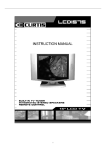
3. DATA ON MEASUREMENT BY PRINTER
▼ Results on Printing Paper
Classification of the blood pressure
: National High Blood Pressure Education Program, National Heart, Lung and Blood institute, NIH
(JNC7, 2003)
- 29 -
Note
- When pressure is high with the jammed air hose, message appears on the printer as
ERROR PRESSURE.
When the message is repeated, call for maintenance service.
- When pressure is low as air leaks, message appears on the printer as ERROR
CUFF.
When the message is repeated, call for maintenance service.
- When the subject moves or speaks while in testing, message appears on the printer
as ERROR MEASURE.
Try to retest after a while. If the message is repeated, call for maintenance service.
- 30 -
OPTION
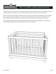
1. Reverse monitor
1) Attachment of the reverse monitor
① Put support of reverse monitor in the direction of arrow.
② Attach reverse monitor into reverse monitor support as above.
③④ Put guide board in the direction of arrow and then complete it.
2) Connect
Connect reverse monitor and a blood pressure monitor to the rear ‘BACK
MONITOR PORT’ in the body, using cable.
3) Composition
① LCD display
Shows information and proceedings.
Also marks result, such as B.M.I. and fatness after completing the measurement.
② Indicating part of systolic blood pressure
Indicating the measured systolic blood pressure.
③ Indicating part of the diastolic blood pressure
Indicating the measured diastolic blood pressure.
④ Indicating part of pulse
Indicating the measured pulse.
⑤ ID button
Used when putting user’s ID number.
- 31 -
⑥ Weight button
Used when putting user’s body weight.
⑦ Height button
Used when putting user’s height.
⑧ Numbers and • button
Used when putting numbers such as ID, body weight, height etc.
Use ‘•’ button in order to put a decimal point in case of body weight, height.
For example, if body weight is 68.9kg, put ‘weight button→6→8→•→9’ in order.
⑨ Print button
Press in the result screen, and the measured result is printed.
⑩ STOP button
When you push a button while putting some information, the information is all removed, and
initialized.
When pushing a button while measuring, stop measuring, and therefore cuff is back to the original
state.
⑪ START button
When pushing a button after putting ID, weight and height, automatically cuff is pressurized and it
starts measuring.
Reverse monitor
② Systolic blood pressure
③ Diastolic blood pressure
④ Pulse
⑩ STOP button
⑧ Number button
① LCD screen
⑤ ID button
⑪ START button
⑨ PRINT button
⑧ • button
⑥ WEIGHT button
- 32 -
⑦ HEIGHT button
4) Measurement
① Input data
ID: After pressing ‘ID’ button in the initial screen, put ID, using 0~9 numeric button.
(go back to the initial screen unless you don’t put for 40 seconds.)
- ID limitation you can put is 000000001~999999999.
Weight: After putting ID, putting ‘WEIGHT’ button, you put body weight, using 0~9
numeric button. (go back to the initial screen unless you don’t put for 40
seconds.)
- Body weight limitation you can put is 10.0~248.0kg.
Height: After putting body weight, putting ‘HEIGHT’ button, you put height, using
0~9 numeric button. (go back to the initial screen unless you don’t put for 40
seconds.)
- Height limitation you can put is 10.0~238.0cm.
Note
In case of cardholders, in putting card, private information(ID, weight, height) is
displayed in reverse monitor.
In case for you to want to modify weight or height, you push ‘weight’ button or ‘height’
button, and then modify it.
When putting card, it’s impossible for you to modify ID.
② Measurement
When you finish input data, press ‘START’ button, and then begin to measure.
When measurement is begun, animation notifying ‘measuring’ is displayed.
Note
When putting reverse monitor, you must push ‘START’ button on reverse monitor,
and then height, weight, body mass index, fatness is displayed in the screen of
thermal paper and reverse monitor.
Since weight, height you put is reflected on the result body mass index(B.M.I.),
fatness, you must put accurately.
- 33 -
③ Result
When measurement is complete, body mass index (B.M.I.), fatness is displayed
based on ID, weight and height in LCD.
④ Standard for judging result
• Body Mass Index (B.M.I.): this is calculated by dividing body weight by the square of height in meter.
section
thin
normal
<18.5kg/m
2
overweight
18.5~<25.0kg/m
2
25.0~<30.0kg/m
obese
2
30kg/m2 and over
• Fatness: value showing your current fatness of weight for standard weight(%)
[{(current weight-standard weight)/standard weight}X100]+100
standard weight=height(m)2 X 22
section
Very thin
thin
normal
overweight
obese
<80%
80%~90%
90%~110%
110%~120%
>120%
- 34 -
2. MAGNETIC CARD
Machine manager can issue cards through supportive card issuer, in machine’s delivery, you can issue
it yourself.
When machine manager issues cards, please refer to card issuer or program manual.
1) Setting
In card’s using, you should set CARD ON/OFF in the rear part by ‘ON’.
Note
CARD ON/OFF switch of the rear part of the machine must be set by 「ON」in
order to use card. In using card, if the validation date has been expired, or the
damaged card is inserted, the voice message “You cannot use ID card.” appears. In
this case, you purchase a new card, and insert, so you can measure.
2) Measurement
① Card recognition
You hold your card and then swipe it up and down from card reader.
If card is recognized normally, it sounds ‘Ttiriring~’, and it becomes in the state of being ready for
measurement.
In connected reverse monitor, ID stored in a card is displayed in the reverse monitor.
(Then, you can put weight and height in the reverse monitor.)
② Measurement
If you finish recognizing card, voice and message ‘Please press the start button’ comes out. Push the
start button, and then begin to measure. When measurement started, cuff pressure begins.
③ Result
When the measurement is completed, systolic blood pressure, diastolic blood pressure, pulse is
displayed on the LED.
- 35 -
④ Print-out the result of the measurement
▼ using only magnetic card
▼ Magnetic Card + reverse monitor
- 36 -
3. RFID card
Machine manager can issue cards through supportive card issuer, in machine’s delivery, you can issue
it yourself.
When machine manager issues cards, please refer to card issuer or program manual.
1) Setting
In card’s using, you should set CARD ON/OFF in the rear part by ‘ON’.
2) Measurement
① card recognition
You hold your card and then touch on card reader.
If card is recognized normally, it sounds ‘Ttiriring~’, and it becomes in the state of being ready for
measurement.
In connected reverse monitor, ID stored in a card is displayed in the rear monitor.
(Then, you can put weight and height in the reverse monitor.)
② Measurement
If you finish recognizing card, voice and message ‘Please press the start button’ comes out. Push the
start button, and then begin to measure.
When measurement started, cuff pressure begins.
③ Result
When the measurement is completed, systolic blood pressure, diastolic blood pressure, pulse is shown
in the LED.
Note
1. In using card(Magnetic&RFID card),
previous measured result is stored by six
times, it shows the total seven times measured result including current measure
result. When you push ‘START’ button in the result screen, the current measured
result and six times accumulated data is displayed in LCD. In Printing-out, the
current measured result and the accumulated data confirming change of blood
pressure are output.
2. In case of using card and reverse monitor(option), you put your weight and
height after putting card. Then both B.M.I. and fatness are output.
Weight and height in reverse monitor are stored, and in case of remeasuring it,
you don’t need to repeat it.
(The method of putting for the reverse monitor, please refer to p. 24.)
- 37 -
④ output the result of measurement
▼ in using only RFID card
▼ RFID card+ in putting the rear monitor
- 38 -
MAINTENANCE
- 39 -
- 40 -
ERROR & REPAIR
Error
Cause
Repair
ERROR PRESSURE
pressure is high with the
jammed air hose
When
the
repeated,
message
call
is
for
maintenance service.
ERROR CUFF
pressure is low as air leaks
When
repeated,
the
message
call
is
for
maintenance service.
ERROR MEASURE
subject
moves or speaks
while in testing
- Don’t move or speak.
- When the message is
repeated,
call
maintenance service.
- 41 -
for
AFTER SERVICE
1. AFTER SERVICE
If there is any problem with the unit, please follow the steps below;
※ Contact our company’s Overseas Service Department immediately.
After gathering the model name, Serial Number, date of purchase and description of the problem,
contact our company with information shown below.
※
Try to solve the problem over the phone with the personnel of local service department.
If the problem cannot be solved over the phone, just return to service department directly.
※
Our company or local distributor will make available on-request circuit diagrams, component part list,
descriptions, calibration or other information which will assist your appropriately qualified technical
personnel to repair those parts of unit which are designated by our company as repairable.
How to contact our company
Write us at:
JAWON MEDICAL CO., LTD
29, Gongdan 4-ro, Jillyang-eup, Gyeongsan-si, Gyeongsangbuk-do, Korea
TEL: 82-53-856-0993
FAX: 82-53-856-0995
(You can also contact the following representative or your local distributor)
2. PACKING AND TRANSPORT
Our company follows his packing ways to protect any impact during transporting etc. So please do not
transport or move the unit without our company’s packing condition as your wishes.
The normal storage environment; -20°C~ 60°C of temperature, Humidity is less than 95% noncondensing.
- 42 -
SPECIFICATION
Model
EASY X 800(R)
EASY X 800(L)
Measuring method
Oscillometric
Display mode
High Brightness LED (197X145mm) display
Systolic/Diastolic/Mean blood pressure, Pulse pressure, Pulse,
Result Contents
Blood pressure assessment, Pulse wave pattern
Reverse Monitor(Option): Systolic/Diastolic blood pressure,
Pulse, ID No, B.M.I., and Fatness
Measuring range
Pressure 30~300mmHg, Pulse 30~200beats/minute
Accuracy
Pressure ±3mmHg or ±3%, Pulse ±3%
Resolving Power
1mmHg
Pressurizing method
DC Motor
Cuff type
Belt type
Pressurizing time
Approx. 10 seconds
Measuring time
Approx. 33 seconds
Printer
Thermal printer
Power supply
Input-AC 230V, 50Hz
Output-DC 12V, 5A ADAPTER
Power consumption
60VA
Ambience for operation
Temperature 10~40℃, Humidity 30~75%
Ambience for storage
Temperature -20~60℃, Humidity Less than 95%
Data transmission
RS-232C
Dimension
463(W) × 461(D) × 276(H) mm
Weight
Approx. 11kg
Measuring parts
EASY X 800(R): Right arm
- 43 -
EASY X 800(L): Left arm
WARRANTY
WARRANTY
Item
Automatic Blood Pressure Monitor
Model
EASY X 800(R/L)
Warranty period
1year (main unit only)
Serial NO.
Date of purchase
Customer
Month
Day
Name:
Year
TEL:
Address:
Dealer
Name:
TEL:
Address:
Date
Note
Defection
Confirmation
- When you receive this warranty, make sure that the name of the dealer and the
month, day and year of purchase are all completed.
- This warranty will not be reissued, please keep it in a safe place.
- 44 -
Periodic Check List
Management No.
Item
Inspection Subject
Requirements
Judgment
No scratch, crack,
Pass/Fail
Visual Check
Mainframe
1 Enclosure
deformation and rust
Accessories
2 Labels and panels
No peeling and dust
Pass/Fail
3 Keys
No damage
Pass/Fail
4 Cuffs
No scratch and damage
Pass/Fail
1 Power cord
No scratch and damage
Pass/Fail
2 User manual
Kept in proper place
Pass/Fail
1 Keys
Smooth operation
Pass/Fail
2 Recorder
Smooth operation with no
Pass/Fail
Mechanical Check
Mainframe
abnormal sound
Accessories
3 Cuffs
Smooth operation
Pass/Fail
1 Power cord
Smooth operation and
Pass/Fail
removal
Electrical Check
Performance
1 Power supply
Screen display upon
Pass/Fail
power-on
2 Display
No abnormality and
Pass/Fail
flickering
3 Printing
printing possible
Pass/Fail
4 Measurement
Proper measurement
Pass/Fail
General Judgment
Model
Pass/Fail
EASY X 800
Serial No.
Installation place
Check date
Date of purchase
Checked by
Copy this sheet for use
If repair is required, write down so in the Remarks column.
- 45 -
Approved by
Remarks
Daily Check List
Management No.
Item
Visual Check
Mainframe
Inspection Subject
Judgment
1 Enclosure
No
scratch,
crack,
Pass/Fail
deformation and rust
2 Labels and panels
3 Keys
No peeling and dust
No damage
Pass/Fail
Pass/Fail
No scratch and damage
No scratch and damage
Kept in proper place
Pass/Fail
Pass/Fail
Pass/Fail
Smooth operation
Pass/Fail
4 Cuffs
1 Power cord
Accessories
2 User manual
Mechanical Check
1 Keys
Mainframe
2 Recorder
Accessories
Requirements
1 Power cord
Smooth operation with no
Pass/Fail
abnormal sound
Smooth
removal
operation
and
Pass/Fail
Electrical Check
Performance
1 Power supply
Screen
display
power-on
upon
2 Display
No
abnormality
flickering
and
Pass/Fail
Pass/Fail
3 Printing
Waveform printing possible Pass/Fail
4 Measurement
Proper measurement
Pass/Fail
Other
1 Clock
Present date/time
Pass/Fail
General Judgment
Pass/Fail
Model
EASY X 800
Serial No.
Installation place
Date of purchase
Check date
Checked by
Approved by
Copy this sheet for use
If repair is required, write down so in the Remarks column.
Remarks
Service center
TEL: 82 - 2 - 587 - 4056
82 - 53 - 856 - 0993
If the problems continue, call the service center. When you ask
for service, the manufacturer’s label, serial number, date of
original purchase and explanation of malfunction will be required.
※ For purpose of improvement, specifications and subject to change
without notice.
※ Our company name will be changed to JANEX MEDICAL.
HEAD OFFICE: 29, Gongdan 4-ro, Jillyang-eup, Gyeongsan-si,
Gyeongsangbuk-do, Korea
TEL: 82-53-856-0993, FAX: 82-53-856-0995
EUROPEAN REPRESENTATIVE: VITAKO Sp. z o.o.
UL. MALEJ SYRENKI 2 71-790
SZCZECIN, POLAND TEL: 91
8522900 / 901 FAX: 91 8522910
JW-EX800E-20150930
2012.12 Rev
Rev4.0
1.1