1
The device bears the CE label in accordance with the provisions of Medical Device
Directive 93/42/EEC.
THE PERSONS RESPONSIBLE FOR PLACING DEVICES ON THE EC MARKET
UNDER MDD 93/42/EEC
JAWON MEDICAL CO.,LTD.
29, Gongdan 4-ro, Jillyang-eup, Gyeongsan-si, Gyeongsangbuk-do, Korea
TEL: 82-53-856-0993, FAX: 82-53-856-0995
VITAKO Sp. z o.o.
UL. MALEJ SYRENKI 2 71-790 SZCZECIN, POLAND
TEL: 91 8522900 / 901, FAX: 91 8522910
2
TABLE OF CONTENTS
• INTRODUCTION..................................................................................................................
5
1. INDICATIONS .................................................................................................................
5
2. WORD DEFINITIONS......................................................................................................
5
3. CLASSIFICATION AND COMPLIANCE..........................................................................
6
4. SAFETY PRECAUTIONS................................................................................................
6
5. SAFETY SYMBOLS AND INFORMATION......................................................................
9
6. Guidance for Electromagnetic compatibility(EMC)………………………………..
12
• TERMS OF EACH PART AND FUNCTIONS.......................................................................
16
1. FRONT PART..................................................................................................................
16
2. REAR PART................................................................................................................…
18
3. ACCESSORIES..............................................................................................................
20
4. OPTIONS.......................................................................................................................
20
• INSTALLATION...................................................................................................................
21
1. CONNECTING ADAPTER.............................................................................................
21
2. LOADING THE PRINT PAPER....................................................................................
21
3. CONNECTING PORTS..................................................................................................
23
4. CONNECTING PRINTER...............................................................................................
23
5. CONNECTING PEDAL SWITCH...................................................................................
24
6. CONNECTING HAND SWITCH.....................................................................................
24
• SYSTEM SETUP................................................................................................................
25
1. Entering SYSTEM SETUP.............................................................................................
25
2. Menu..............................................................................................................................
25
3. Entering ‘MENU’ view....................................................................................................
25
4. How to escape from SYSTEM SETUP..........................................................................
25
5. How to move into SYSTEM SETUP..............................................................................
25
6. SETUP.........................................................................................................................
26
• MEASUREMENT................................................................................................................
31
1. CAUTIONS FOR MEASUREMENT...............................................................................
31
2. MEASUREMENT...........................................................................................................
32
3. RESULT SHEET……………………………....................................................................
36
4. The measuring method if ID is on..................................................................................
37
5. The measuring method by using ‘Three measurement MODE’.....................................
38
• MAINTENANCE..................................................................................................................
40
• ERROR & REPAIR..............................................................................................................
41
• AFTER SERVICE................................................................................................................
42
3
1. AFTER SERVICE..........................................................................................................
42
2. PACKING AND TRANSPORT.......................................................................................
42
• SPECIFICATION.................................................................................................................
43
• WARRANTY........................................................................................................................
44
4
INTRODUCTION
We highly appreciate that you chose our company’s product.
You are kindly requested to be familiar with these directions before using this product and
always keep it together with the product. In case you are not sure about any directions or
problems arising while using the product, please contact our service center.
We will provide you with detailed instructions.
1. INDICATIONS
Indications for use
The EX PLUS 1300 is intended to measure systolic and diastolic blood pressure and pulse rate
in adults with an arm circumference of 22-33 cm.
The EX PLUS 1300 is intended for use in physicians’ offices, hospitals, clinics and other medical
facilities where non-invasive blood pressure is performed on patients and invasive measurement
is contraindicated.
The blood pressure can be measured using 2 different methods as follow:
1. one measurement with left or right arm
2. two measurements with both arms(BP simultaneous dual-arm measurement)
Contraindications for use
As with any non-invasive measurement device, there are clinical conditions which can influence
the accuracy of the results. Also, the subject’s position, physiological condition and other
environmental factors can affect the measurement/calculation.
The EX PLUS 1300 Non-Invasive Blood Pressure Monitor should not be used with patients who
have the following conditions:
1. Patients with a known arrhythmia.
2. Patients with insufficient peripheral circulation, acute cases of low blood pressure or low
temperature.
3. Patients who use a pacemaker.
4. Patients experiencing a seizure.
5. Children younger than 18 years old.
6. Patients who should not have blood pressure measurements taken from their arms.
7. Patients with an artificial heart.
8. Patients whose artery cannot be found by palpation.
2. WORD DEFINITIONS
To ensure safe operation and long term performance stability, it is essential that you fully
understand the functions, operating and maintenance instructions by reading this manual
before operating your unit.
Particular attention must be paid to all warnings, cautions and notes incorporated herein.
The following conventions are used throughout the manual to denote information of special
emphasis.
5
3. CLASSIFICATION AND COMPLIANCE
1) This device is classified as;
- Class 1 type-BF against electric shock
- Ordinary equipment without protection against ingress of water
- Equipment not suitable for use in presence of a flammable anesthetic mixture by standard of
EN 60601-1:2006(Safety of Medical Electrical Equipment)
2) This device is complied with Class A for Noise-Emission, Level B for Noise-immunity, by
standard of IEC 60601-1-2:2007(Electromagnetic Compatibility Requirements).
3) This device is complies with the EN 1060-1: 1995+A2:2009 Non-invasive
Sphygmomanometers general requirements as well as EN 1060-3: 1997+A2:2009
supplementary requirements for electro-mechanical blood pressure measuring systems.
4. SAFETY PRECAUTIONS
This device is designed and manufactured with consideration of safety of the operator and
subject and also to the reliability of the unit.
The following precautions must be observed for additional safety;
This device is designed and manufactured with consideration of safety of the operator and
subject and also to the reliability of the unit.
The following precautions must be observed for additional safety;
1) The unit must be operated only by, or under supervision of a qualified person with our
company or our distributors.
2) This device is specified as Class 1 type BF unit under the standard of EN 606011:2006 (Safety of Medical Electrical Equipment).
Therefore, patients must not touch or handle inner side of the system at any time.
3) Do not modify the unit. If any modification is needed, ask our company or its authorized
dealer for service.
4) The unit has previously been adjusted in the factory for optimum performance.
Do not attempt to adjust switches or any other things except those specified in this
manual for operation.
5) If you have experienced any trouble with the unit, switch it off immediately, and contact
our company or its authorized dealer for assistance.
6) If you plan to connect any device of other manufacturers electrically or mechanically to
the unit, contact our company or its authorized dealer for instructions before doing so.
When you connect computer or other system to the unit (RS-232C), the attached
systems should be those certified by IEC 950 or equivalent standards for data
processing equipment.
Configurations shall comply with the system standard EN 60601-1:2006.
Everybody who connects additional equipment to the signal input part or signal output
part configures a medical system standard EN 60601-1:2006.
If in doubt, consult the A/S department of local distributor.
7) Avoid the following environments for storage;
- Where the ambient temperature falls -20°C or exceeds 60°C.
- Where the atmospheric pressure falls below 70kPa (700mbar) or exceeds 106kPa
(1060mbar).
- Where the humidity is over 95% non-condensing.
- Where the unit is exposed to spray or splashing water.
6
- Where the unit is exposed to dust.
- Where the unit is exposed to water vapor.
- Where the unit is exposed to salty atmosphere.
- Where the unit is exposed to explosive gas.
- Where the unit is exposed to excessive shocks or vibrations.
- Where the angle of inclination of mounting surface exceeds 10 degrees.
- Where the unit is exposed to direct sunlight.
8) This equipment has been tested and found to comply with the limits for medical devices
to the IEC 60601-1-2:2007. These limits are designed to provide reasonable protection
against harmful interference in a typical medical installation.
This equipment
generates uses and can radiate radio frequency energy and, if not installed and used in
accordance with the instructions, may cause harmful interference to other devices in
the vicinity. However, there is no guarantee that interference will not occur in a
particular installation. If this equipment does cause harmful interference to other
devices, which can be determined by turning the equipment off and on, the user is
encouraged to try to correct the interference by one or more of the following measures:
- Reorient or relocate the receiving device.
- Increase the separation between the equipment.
- Connect the equipment into an outlet on a circuit different from that to which the other
device(s) are connected.
- Consult the manufacturer or field service technician for help.
9) Do not to touch signal input, signal output or other connectors, and the patient
simultaneously.
10) a statement that MEDICAL ELECTRICAL EQUIPMENT needs special precautions
regarding EMC and needs to be installed and put into service according to the EMC
information provided in the ACCOMPANYING DOCUMENTS;
11) a statement that portable and mobile RF communications equipment can affect
MEDICAL ELECTRICAL EQUIPMENT.
12) Please consult a physician or a trained health professional for interpretation of
measurement results.
13) No phthalates are used for this product and its container.
14) The cuff is not made with natural rubber latex
Caution
1. Measurements may be impaired if this device is used near televisions,
microwave ovens, X-ray equipment or other devices with strong electrical
fields. To prevent such interference, use the meter at a sufficient distance
from such devices or turn them off.
2. Incorrect operation or failure of user to maintain the unit spares the
manufacturer or his agent of the responsibility for system’s non-compliance
with specifications or responsibility for any damage or injury.
7
Caution
This manual is made for informational purpose and this manual and product
are not meant to be a substitute for the advice provided by your own
physician or other medical problem. You should not use the information
contained in the product for diagnosis or treatment of health problem or
prescription of medication by yourself.
If you have or suspect that you have a medical problem, consult with your
physician promptly.
Defective unit or accessories must be packed in the replacement cartons to
be shipped off from you to our company.
Shipping and insurance costs for return of defective unit must be prepaid by
the users.
8
5. SAFETY SYMBOLS AND INFORMATION
The International Electrotechnical Commission (IEC) has established a set of symbols for
medical electrical equipment which classifies a connection or warning of any potential hazard.
The classifications and symbols are shown below. Save these instructions for your safety.
Degree of protection against electric shock: TYPE BF
Please observe operating instructions
General warning sign
General prohibition sign
General mandatory action sign
Caution
Waste Electrical and Electronic Equipment (WEEE)
The device could be sent back to the manufacturer for recycling or
proper disposal after their useful lives. Alternatively the device shall be
disposed in accordance with national laws after their useful lives.
"OFF" (only for a part of equipment)
9
"ON" (only for a part of equipment)
This symbol is used inside system.
Identifies the point where the safety ground of the system is fastened to
the chassis.
Do not open. This is for factory only.
Alternating current
Direct current
Date of manufacture
Manufacturer
Non-ionizing radiation
CE mark
Serial No.
Foot switch
Start or stop the measurement.
And, when your arm is oppressed due to high pressurizing or
irregular operation is done, press this button then the cuff will be
exhausted rapidly.
10
Hand-held switch
Start or stop the measurement.
And, when your arm is oppressed due to high pressurizing or
irregular operation is done, press this button then the cuff will be
exhausted rapidly.
Authorized representative in the European community.
Keep dry
RoHS2
11
6. Guidance for Electromagnetic compatibility (EMC)
Details about the electromagnetic compatibility (EMC) of the EX PLUS 1300 are given below.
Before using the EX PLUS 1300, be sure to read and understand the following information.
1) Guidance and manufacturer’s declaration – electromagnetic emissions
The EX PLUS 1300 is intended for use in the electromagnetic environment specified below. The
customer or the user of the EX PLUS 1300 should assure that it is used in such an environment.
Emissions test
Compliance
RF emissions
CISPR 11
Group 1
RF emissions
CISPR 11
Harmonic
emissions
IEC 61000-3-2
Voltage
fluctuations/
flicker emissions
IEC 61000-3-3
Electromagnetic environment – guidance
The EX PLUS 1300 uses RF energy only for its
internal function. Therefore, its RF emissions are very
low and are not likely to cause any interference in
nearby electronic equipment.
Class B
Class A
Compliance
The EX PLUS 1300 is suitable for use in all
establishments, including domestic establishments
and those directly connected to the public low-voltage
power supply network that supplies buildings used for
domestic purposes.
2) Guidance and manufacturer’s declaration – electromagnetic immunity
The EX PLUS 1300 is intended for use in the electromagnetic environment specified below. The
customer or the user of the EX PLUS 1300 should assure that it is used in such an environment.
Immunity test
IEC 60601 test
level
Compliance
level
Electrostatic
discharge(ESD)
IEC 61000-4-2
±6kV: Contact
±8kV: Air
±6kV: Contact
±8kV: Air
Electrical
fast
transition/burst
IEC 61000-4-4
±2kV:
Power
supply lines
±1kV:
Input/output lines
Surge
IEC 61000-4-5
±1 kV differential
mode
±2 kV common
mode
Voltage
<5 % UT
drops,
±2kV:
Power
supply lines
±1kV:
Input/output
lines
±1
kV
differential
mode
±2 kV common
mode
<5 % UT
12
Electromagnetic
environmentguidance
Floors should be wood, concrete or
ceramic tile. If floors are covered
with synthetic material, the relative
humidity should be at least 30 %.
Mains power quality should be that
of a typical commercial or hospital
environment.
Mains power quality should be that
of a typical commercial or hospital
environment.
Mains power quality should be that
dips,
and
fluctuations of
input
power
supply line IEC
61000-4-11
Magnetic field of
commercial
frequency
(50/60Hz)
IEC 61000-4-8
(>95 % dip in UT)
for 0,5 cycle
40 % UT
(60 % dip in UT)
for 5 cycles
70 % UT
(30 % dip in UT)
for 25 cycles
<5 % UT
(>95 % dip in UT)
for 5 sec
3 A/m
(>95 % dip in
UT)
for 0,5 cycle
40 % UT
(60 % dip in UT)
for 5 cycles
70 % UT
(30 % dip in UT)
for 25 cycles
<5 % UT
(>95 % dip in
UT)
for 5 sec
of a typical commercial or hospital
environment. If the user of the EX
PLUS 1300 requires continued
operation during power mains
interruptions, it is recommended that
the EX PLUS 1300 be powered from
an uninterruptible power supply or a
battery.
Power frequency magnetic fields
should be at levels characteristic of
a typical location in a typical
commercial or hospital environment.
3 A/m
Note
UT is the a.c. mains voltage prior to application of the test level.
3) Guidance and manufacturer’s declaration – electromagnetic immunity 2
The EX PLUS 1300 is intended for use in the electromagnetic environment specified below. The
customer or the user of the EX PLUS 1300 should assure that it is used in such an environment.
Compliance Electromagnetic
environmentImmunity test
IEC 60601 test level
level
guidance
Portable
and
mobile
RF
communications equipment should be
used no closer to any part of the EX
PLUS 1300, including cables, than the
recommended separation distance
Conducted RF
3 Vrms
3 Vrms
calculated
from
the
equation
IEC 61000-4-6
150 kHz to 80 MHz
applicable to the frequency of the
transmitter.
Radiated RF
IEC 61000-4-3
3 V/m
80 MHz to 2,5 GHz
3 V/m
Recommended separation distance
d =1.2
d =1.2
13
80 MHz to 900 MHz
d =2.3
900 MHz to 2,5 GHz
where P is the maximum output power
rating of the transmitter in watts (W)
according
to
the
transmitter
manufacturer
and
d
is
the
recommended separation distance in
meters (m).
Field strengths from fixed RF
transmitters, as determined by an
a
electromagnetic site survey, should
be less than the compliance level in
b
each frequency range.
Interference may occur in the vicinity
of equipment marked with the
following symbol:
Caution
1. At 80 MHz and 900 MHz, the higher frequency range applies.
2 These guidelines may not apply in all situations. Electromagnetic
propagation is affected by absorption and reflection from structures, objects
and people.
a
Field strengths from fixed transmitters, such as base stations for radio
(cellular/cordless) telephones and land mobile radios, amateur radio, AM
and FM radio broadcast and TV broadcast cannot be predicted theoretically
with accuracy. To assess the electromagnetic environment due to fixed RF
transmitters, an electromagnetic site survey should be considered. If the
measured field strength in the location in which the EX PLUS 1300 is used
exceeds the applicable RF compliance level above, the EX PLUS 1300
should be observed to verify normal operation. If abnormal performance is
observed, additional measures may be necessary, such as reorienting or
relocating the EX PLUS 1300.
b
Over the frequency range 150 kHz to 80 MHz, field strengths should be less
than 3 V/m.
14
4) Recommended separation distances between portable and mobile RF communications
equipment and the EX PLUS 1300
The EX PLUS 1300 is intended for use in an electromagnetic environment in which radiated RF
disturbances are controlled. The customer or the user of the EX PLUS 1300 can help prevent
electromagnetic interference by maintaining a minimum distance between portable and mobile
RF communications equipment (transmitters) and the EX PLUS 1300 as recommended below,
according to the maximum output power of the communications equipment.
Rated maximum Separation distance according to frequency of transmitter
output power
m
of transmitter
150 kHz to 80 MHz
80 MHz to 900 MHz
900 MHz to 2,5 GHz
W
d =1.2
d =1.2
d =1.2
0.01
0.12
0.12
0.23
0.1
0.38
0.38
0.73
1
1.2
1.2
2.3
10
3.8
3.8
7.3
100
12
12
23
For transmitters rated at a maximum output power not listed above, the recommended
separation distance d in meters (m) can be estimated using the equation applicable to the
frequency of the transmitter, where P is the maximum output power rating of the transmitter in
watts (W) according to the transmitter manufacturer.
Caution
1. At 80 MHz and 900 MHz, the separation distance for the higher frequency
range applies.
2. These guidelines may not apply in all situations. Electromagnetic
propagation is affected by absorption and reflection from structures, objects
and people.
15
TERMS OF EACH PART AND FUNCTIONS
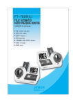
1. FRONT PART
① START / STOP BUTTON
Press ‘Start’ to start the measurement. The cuff starts winding up automatically and begins to
pressurize. Press the button to stop the measurement. Pressurization will stop and the air will
be exhausted from the cuff.
② INFORMATIOM BOARD
This signs explain the measuring method and notice. Please follow the signs before the
measurement.
③ LCD DISPLAY
The measurement process is displayed in letters and animations. After the test, the result is
displayed; Systolic/ Diastolic blood pressure, Pulse, Pulse wave pattern, Blood pressure.
④ CLOCK SECTION (Date and Time)
On the right upper corner of LCD screen, date and time are displayed.
⑤ PRINTER COVER
It protects the printer.
⑥ Printer outlet of the result sheet
Result sheet is automatically printed out. Automatic cutter is equipped inside and it cuts the
result sheet automatically.
⑦ CUFF
It automatically wraps and releases the arm for measurement.
⑧ ARM REST
When the arm is placed on the cuff, it sustains the arm and makes the right position.
⑨ HUMAN SENSOR
When a user approaches, power is automatically turned on and vice versa. When the user is
wearing black, it may not sense the movement. Therefore, the user in black clothes rolls up
the sleeves and measures.
⑩ EMERGENCY STOP BUTTON
When a user feels the pain due to high pressurization or irregular operation, press the button
to stop the operation. The air will be rapidly exhausted from the cuff.
⑪ HAND SWITCH REST
When the cable switch is used, switch rest can be placed in the right side of device.
⑫ HAND SWITCH
When the user measures blood pressure on both arms, push the hand switch to START and
STOP the device.
⑬ PEDAL SWITCH
It is placed under the cart. It works as ‘START/STOP’.
16
FRONT PART
② INFORMATION BOARD
⑧ ARM REST
④ CLOCK SECTION
③ LCD DISPLAY
⑨ HUMAN SENSOR
⑦ CUFF
⑤PRINTER COVER
⑩ EMERGENCY
STOP BUTTON
⑥ AUTOMATIC CUTTER
①START/STOP BUTTON
⑫ HAND SWITCH
⑪ HAND SWITCH REST
The side part of cart
⑬ PEDAL SWITCH
The under part of cart
17
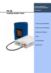
2. REAR PART
POWER
It turns the power on and off.
② POWER INPUT
It connects the adapter.
③ R-CAL
It is only for the inspection. Do not open it.
④ L-CAL
It is only for the inspection. Do not open it.
⑤ EARTH (POTENTIAL EQUALIZATION TERMINAL)
For safety, the device should be placed on the flat surface.
⑥ COMMUNICATION PORTS (RS-232C)
It connects the main to other equipments with cable (RS-232C) to transfer the data.
⑦ USB PORT (A TYPE)
It connects the main body with USB cable (A type).
⑧ USB PORT (B TYPE)
It connects the main body with USB cable (B type).
⑨ PEDAL BUTTON PORT
It connects the PEDAL switch.
⑩ HAND BUTTON PORT
It connects the HAND switch.
⑪ INFORMATION BOARD FIXER
It fixes the Information Board.
①
18
REAR PART
⑪ INFORMATION
BOARD FIXER
⑧ USB PORT
(A TYPE)
⑩ HAND BUTTON
③ R-CAL
① POWER
④ L-CAL
⑦ USB PORT
(B TYPE)
⑥ COMMUNICATION
PORT
② POWER INPUT
Note
PORT
⑤ EARTH
⑨ PEDAL BUTTON
PORT
The operator should not touch both USB port and the patient’s body
simultaneously.
19
3. ACCESSORIES
Adapter/Power cable
User Manual
Information board
PEDAL /HAND SWITCH
Thermal paper / ROLLER
Cart
4. OPTIONS
Chair
A4 RESULT SHEET
20
INSTALLATION
1. CONNECTING ADAPTER
Connect the adaptor to the power input on the back of the device.
Turn on the POWER switch.
Caution
In order to avoid the risk of electrical shock, connect this device only to the
power supply equipped with the protective grounding.
Caution
When connecting adaptor, place the arrow mark of adaptor
connection part up and correctly stick it in the socket on the rear
of the main body.
Wrong connection could be a fire hazard.
21
2. LOADING THE PRINT PAPER
①
②
③
④
⑤
⑥
Pull the Top button up. Then press the Side button. Open the upper printer cover.
Put the roller into the center hole of the thermal paper.
Insert the thermal paper with the roller into the holder as shown in the picture.
Take the edge of the paper out.
Close the cover.
It automatically cuts the paper.
Note
Thermal paper doesn’t need the ink.
One side is smooth and another is rough. It prints the letter only on the
smooth side.
Always check the remainder of the paper and replace it at any time.
When the red line appears on the right corner of the paper, replace the paper.
Use only the exclusive paper (57mm).
Keep paper rolls in a dark and ventilated place.
Avoid the dust on the paper.
Do not pull the paper during printing. It may cause a jam.
When the paper is not loaded correctly, the paper will not be printed out
properly and it may cause the breakdown.
When the printer cover is not properly closed, the paper can be jammed
inside. When the problem occurs, check the printer cover.
22
3. CONNECTING COMMUNICATION PORT
To transmit the data, connect EX PLUS 1300 to a computer or other external devices.
Insert USB cable to the communication port and connect it to the computer as shown in the
picture below.
4. CONNECTING PRINTER (Option)
Connect A4 printer for the output in A4 size.
Insert USB cable to the communication port and connect it to the printer as shown in the picture
below.
23
5. CONNECTING PEDAL SWITCH
Connect the PEDAL SWITCH as shown in the picture.
6. CONNECTING HAND SWITCH
Connect the PEDAL SWITCH as shown in the picture.
24
SYSTEM SETUP
Set the operating conditions for EX PLUS 1300.
1. Entering SYSTEM SETUP
At the initial screen, press ‘Power' button on the left upper
corner for 4~5seconds. Popup screen appears as shown in the
picture. Press ‘1->2->3->4’ to enter SYSTEM SETUP.
2. Menu
1. DATE TYPE
2. DATE/TIME
3. VOLUME
4. PRINT
5. MEASUREMENT MODE
6. Automatic return to initialized screen
7. LOGO
8. PERSONAL DATA INPUT
9. VOICE
10. PRINT
11. PRINT POSITION
12. PROGRAM INFORMATION
13. MEASUREMENT VIEW
14. DETECTING ARM
15. SELECT LANGUAGE
16. QR DOMAIN
3. Entering ‘MENU’ view
Select the menu on the touch screen.
4. How to escape from SYSTEM SETUP
Press the blue icon on the upper right corner.
The initial screen appears.
25
5. How to move into SYSTEM SETUP
After setting the system from the selected menu, press the blue icon on the upper right corner.
The initial screen appears.
6. Setup
<DATE TYPE>
Set the Date Format.
- Pre-set: YY-MM-DD (Year-Month-Day)
- Select ‘Date type’.
- Press ‘SET’ to save the change.
- Press ‘CLOSE’ and get back to SYSTEM SETUP
menu.
< DATE/TIME >
Set the current time and the date.
- Pre-set: The date released from the factory.
- Select Date/Time and enter the menu.
- Press ‘YEAR’ and the color changes.
- Press’∧’ button to increase the number.
Press‘∨’ button to decrease the number.
- After setting the current year, move to Month.
Set the current month by pressing ‘∧’ and ‘∨’ button.
Set the date, hour, and minute by following the
instructions mentioned above.
- Save the change with ‘SET’ button.
- Press ‘CLOSE’ to get back to SYSTEM SETUP menu.
Note
Press ‘CLOSE’ to stop setting the date and time.
For Date/Time, all settings should be done at once; hour, minute, month, day
and year.
If you press ‘CLOSE’ and stop the setting, the time and date returns to the old
setting.
The function of Time and Calendar keeps running even after the power is off.
Calendar program is set for 100 years, and it adjusts automatically even at a
leap year.
26
< VOLUME >
Set the volume of key sound on the top monitor.
- Pre-set: 2
- Select ‘VOLUME’ and enter the menu.
- Set the volume by pressing ‘∧’, ‘∨’ button.
- Press ‘SET’ to save the change.
- Press ‘CLOSE’ to get back to SYSTEM SETUP menu.
<THERMAL PRINT>
Choose the print option and set the result sheet form.
- Pre-set: ON
- Select ‘THERMAL PRINT’ and enter the menu.
- ON: Result sheet is printed after the measurement.
OFF: Result sheet is not printed after the measurement.
- Press ‘RESULT SHEET FORM’ and enter the menu.
- Select the print form and press ‘SET’ button.
- Press ‘CLOSE’ to get back to ‘THERMAL PRINT’
menu.
- Press ‘CLOSE’ to get back to SYSTEM SETUP menu.
< MEASUREMENT MODE>
Select the measurement mode.
*Simple Measurement mode: Measure blood pressure
on both arms simultaneously at once.
*Three Measurement mode: Measure blood pressure on
both arms 3 times in a row. The average blood pressure
is displayed as a result.
- Pre-set: Simple measurement mode
- Select the ‘MEASUREMENT MODE and enter the menu.
- Select either ‘SIMPLE MEASUREMENT MODE’ or ‘Three Measurement MODE’.
- Set the interval time when ‘Three Measurement MODE’ is selected. The interval time is the
break time between three times of measurements. Select the time from 15sec, 30sec, 45sec
and 60sec. Press ‘SET’ to save the change.
- Press ‘CLOSE’ to get back to SYSTEM SETUP menu.
< CONVERTING TO AUTO STANDBY MODE >
After the measurement, the result screen automatically
returns to the initial screen.
- Pre-set: ON
- Select the ‘Converting to auto standby mode’ and enter
the menu.
- Select either ‘ON’ or ‘OFF’.
- Press ‘SET’ to save the change.
- Press ‘CLOSE’ to get back to SYSTEM SETUP menu.
27
< LOGO >
Set ‘LOGO’ position.
- Select ‘LOGO’ and enter the menu.
- Select either ‘THE UPPER LOGO’ or ‘THE UNDER
LOGO’.
- If the user wants to delete LOGO press ‘DELETE’.
- Press ‘SET’ to save the change.
- Press ‘CLOSE’ to get back to SYSTEM SETUP menu.
< PERSONAL DATA INPUT >
It allows the user to input personal data.
- Select ‘PERSONAL DATA INPUT’ and enter the menu.
- Select either ‘ON’ or ‘OFF’ for ID.
- Select either ‘ON’ or ‘OFF’ for HEIGHT/WEIGHT
INPUT.
- Press ‘SET’ to save the change.
- Press ‘CLOSE’ to get back to SYSTEM SETUP menu.
< VOICE >
It sets the voice guidance.
- Pre-set: ON
- Select ‘Voice’ and enter the menu.
- Select either ‘ON’ or ‘OFF’.
- Press ‘SET’ to save the change.
- Press ‘CLOSE’ to get back to SYSTEM SETUP menu.
< PRINT >
It selects the printing mode of the A4 printer.
(The printer and pre-formatted result sheet is
optional.)
- Select ‘PRINT’ and enter the menu.
- Pre-set: AUTO
- AUTO: It is printed automatically.
Manual: It is printed manually.
Off: It is not printed.
- Press ‘SET’ button on touch pad to save it.
- Press ‘CLOSE’ to get back to SYSTEM SETUP menu.
28
< PRINT POSITION >
It adjusts the printing position in the direction of U-D (updown) and L-R (left-right) to fit to the pre-formatted result
sheet.
- Select ‘PRINT POSITION’ and enter the menu.
- Pre-set: 00 for U-D and 00 for L-R
- Range: 99 for U-D and 99 for L-R
- Choose U-D by pressing ‘▼, ▲’ on touch pad. Choose
L-R by pressing ‘▶, ◀’ on touch pad.
- Pressing ▶ button moves print position down or right.
- Pressing ◀ button moves print position up or left.
- Every single press moves print position by about 0.2 mm.
- Press ‘SET’ button on touch pad to save it.
- Press ‘CLOSE’ to get back to SYSTEM SETUP menu.
Note
L-R (left-right): - is moving to the left and + is moving to the right.
U-D (up-down): - is moving up and + is moving down.
<PROGRAM INFORMATION >
It is for check the program information of this device.
- Select ‘PROGRAM INFORMATION’ and enter the menu.
- Check the version and information of this program.
- Press ‘CLOSE’ to get back to SYSTEM SETUP menu.
<MEASUREMENT VIEW>
It sets the result screen type.
- Pre-set : GENERAL TYPE
- Select ‘RESULT VIEW’ and enter the menu.
- Select the result type.
* GENERAL TYPE: Basal type.
* DIAGRAM TYPE: The Blood pressure displayed by gage.
- Press ‘SET’ button on touch pad to save it.
- Press ‘CLOSE’ to get back to SYSTEM SETUP menu.
29
<DETECTING ARM>
Select operating of detecting arm sensor When
pressurized.
- Pre-set: ON
- Select 'Detecting arm' and enter the menu.
‘ON’: Auto detect arm.
- Press ‘SET’ button on touch pad to save it.
- Press ‘CLOSE’ to get back to SYSTEM SETUP menu.
<SELECT LANGUAGE>
Select the language on device.
- Pre-set: ENGLISH
- Select ‘Select language’ and enter the menu.
Choose the language.
- Press ‘SET’ button on touch pad to save it.
- Press ‘CLOSE’ to get back to SYSTEM SETUP menu.
<QR DOMAIN>
Input the server address of QR code.
- Pre-set: m.jawon.com
- Input server address for want to use.
- Storage by pressing ‘SAVE’ button.
- If you don’t want input, press ‘Initial View’ button and
return initial view..
30
MEASUREMENT
1. CAUTIONS FOR MEASUREMENT
① Take off heavy sweater or shirts.
② Have a rest before the measurement.
③ Do not move or talk during the measurement.
④ Do not measure in following positions; standing, half-sitting, leg-crossed.
⑤ Put your arm properly into the arm support.
⑥ When you roll up the sleeves, make sure that the rolled up sleeves are not pressing the
upper arms.
⑦ When the pulse is running too week and hard to be heard from stethoscope, EX PLUS 1300
can not make a measurement.
⑧ During the measurement, straighten your back and relax your arm.
Caution
This device is only for adult.
31
2. MEASUREMENT
*There are 3 ways to measure blood pressure.
1) Measuring method by using a foot switch.
(Measure blood pressure on both arms simultaneously.)
1) Plug the cable and turn on the power.
2) As the power is on, the message appears as shown in
the picture.
3) Put both arms into the cuff.
4) There’s Pedal Switch placed at the bottom of the cart.
Step down the pedal to start the measurement.
Caution
Place your arm on the arm supporter with
the palm facing up.
Adjust the height of the chair so that the arm
stays on the same height of the heart.
When the arm is placed lower than the
heart, blood pressure will be higher than
actual value, and vice versa.
32
5) Pressurization starts automatically from the cuff
and LCD indicates the current status.
6) When the measurement is completed, LCD screen
displays the results.
At the same time, voice guidance speaks out,
“Measurement completed, pull your arm out please.
Thank you.”
The cuff deflates and turns to the initial state.
Note
When the difference between the two arms is more than 20mmHg for systolic
blood pressure or 10mmHg for diastolic blood pressure, the difference is
indicated in red.
7) The result is printed out automatically.
Note
At the system setup, there’s PRINT ON/OFF. If the print is off, the result sheet
is not printed out.
8) Pull your arm out from the cuff.
- Press the ‘QR code’ on the device screen to enlarge the
icon and scan the ‘QR code’ with a mobile device to save
the data in the server.
After scanning the ‘QR code’, you can check the
measurement data with your mobile device and manage
it at will from the server in which it is saved.
33
9) When you press
button on the result screen,
it indicates which category your blood pressure is
classified into. Gray represents the blood pressure of
your left arm.
10) When you want to measure one more time, press
The whole procedure restarts again.
button.
2) Measuring method by using a hand switch.
(Measure blood pressure on both arms simultaneously.)
①
Plug the cable and turn on the power.
② As the power is on, LCD displays the Standby mode.
③
Put both arms into the cuff.
④
An assistant stands next to the measurer and press ‘START’.
Pressurization starts automatically from the cuff and LCD indicates
the current status.
The next step is same as the instruction ⑤, ⑥, ⑦, ⑧, ⑨, ⑩ from
‘1) Measuring method by using a foot switch’.
3) Measuring method by one arm.
(Measure blood pressure on one arm.)
①
Plug the cable and turn on the power.
② As the power is on, LCD displays the Standby mode.
③
Put right or left arm to the cuff.
Note
For measuring right arm, put right arm into the cuff on the right side.
For measuring left arm, put left arm into the cuff on the left side.
34
④ Press the start
Pressurization starts automatically from the cuff
and LCD indicates the current status.
⑤ When the measurement is completed, LCD screen
displays the results.
At the same time, voice guidance speaks out,
“Measurement completed, pull your arm out please.
Thank you.”
The cuff deflates and turns to the initial state.
35
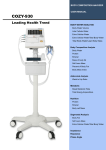
3. Result sheet
▼ Result sheet format (both arms)
▼ Result sheet format (one arm)
▼Classification of the blood pressure
: National High Blood Pressure Education Program, National Heart, Lung and Blood institute,
NIH (JNC7, 2003)
36
4. Measuring method with ID
Enter SYSTEM SETUP. From ‘PERSONAL DATA INPUT’, activate ID use.
1) Input data
ID: On the initial display, press ‘ID’.
Enter ID using the number buttons.
- ID Input Range is from 000000001 to 999999999.
Weight: After entering ID, press ‘WEIGHT’.
Enter weight.
- Weight Input Range is 10.0~248.0kg.
Height: After entering weight, press ‘HEIGHT’.
Enter height.
- Height Input Range is 80.0~238.0cm.
37
2) Measurement
After entering the personal data, press ‘START’.
Pressurization starts automatically from the cuff and
LCD indicates the current status.
3) Result
When the measurement is completed, the user’s ID,
weight, height, Body Mass Index (B.M.I) and fatness
are displayed as shown in the picture.
4) Criterion for judging result
• Fatness: Based on the standard weight, it calculates how fat the user is in percentage.
[{(current weight-standard weight)/standard weight}X100]+100
standard weight=height(m)2X22
section
Very thin
<80%
thin
80%~90%
normal
90%~110%
overweight
110%~120%
obese
>120%
5. The measuring method by ‘THREE MEASUREMENT MODE’.
It measures blood pressure 3 times in a row. The average blood pressure from the three
measurements indicates the more accurate data.
It is possible to measure either one arm or both arms.
System setup -> Measurement Mode ->Three measurement mode
You can set the measuring interval. (15sec, 30sec, 45sec, 60sec)
① Measurement
Put both arms or one arm to the cuff and press ‘START’ button.
Pressurization starts automatically from the cuff and LCD indicates the current status.
38
When the first measurement is completed, device stops until the interval time the user sets.
When the second measurement is completed, device stops until the interval time the user
sets.
It performs the measurements three times in a row.
② Result
After the third measurements, the average blood pressure is indicates as follows.
39
MAINTENANCE
1) Pay attention to allowable current value of power.
2) Avoid direct sunlight, humidity, dust, thick oil and salty or extreme changes in temperature.
3) Do not install or store this device in some space where any chemicals or gas is stored.
4) Do not use this device in any unstable, vibrating, or impact-giving area.
5) Connect the earth placed on the backside of this device to terminal plate to prevent any
electric shock from leakage current or a potential difference.
6) Do not put or drop anything on this device and avoid strong impact.
7) Do not disassemble or remodel this device.
8) If this unit has not been used for a long time, use this after confirming by an expert if all
function and appearance are in good condition.
9) Do not splash any fluid on this device or insert any foreign substances.
10) In case of inserting foreign substances or exposing to particular environment, this device
must be examined by an expert before use.
11) Use the power cable, plug, and fuse that are offered by our company.
At this time, confirm the covering of cable, the state of plug connection, and other check
points to the things below.
• RS 232C cable • USB port • Adapter
12) When pulling out the power cable, turn off the power switch first and then pull the plug out.
13) Storage ambient: Temperature -10 ~ 60 °C, Humidity lower than 95 % (non condensing)
14) Operation ambient: Temperature 10 ~ 40 °C, Humidity 30 ~ 75 % (non condensing)
15) Do not store or use this device under 70 kPa (700 mbar) or over 106 kPa (1060 mbar) of
atmospheric pressure.
16) Cleaning & Disinfection
① Cleaning: When cleaning, use a soft cloth but do not use volatile solvent like benzene and
alcohol or a wet cloth. Wipe out minute dust once per 2 ~ 3 days with a dry cloth.
② Disinfection: Spray alcoholic water of glutaraldehyde disinfect solution. Then, wipe the
enclosure with a soft lint.
17) Refer to “SAFETY PRECAUTIONS.”
40
ERROR & REPAIR
Error
ERROR PRESSURE
Cause
Repair
pressure is high with the When the
jammed air hose
repeated,
message
call
is
for
maintenance service.
ERROR CUFF
pressure is low as air leaks
When
repeated,
the
message
call
is
for
maintenance service.
ERROR MEASURE
subject moves
while in testing
or speaks
- Don’t move or speak.
- When the message is
repeated,
call
maintenance service.
41
for
AFTER SERVICE
1. AFTER SERVICE
If there is any problem with the unit, please follow the steps below;
※ Contact our company’s Overseas Service Department immediately.
After gathering the model name, Serial Number, date of purchase and description of the
problem, contact our company with information shown below.
※ Try to solve the problem over the phone with the personnel of local service department.
If the problem cannot be solved over the phone, just return to service department directly.
※ Our company or local distributor will make available on-request circuit diagrams, component
part list, descriptions, calibration or other information which will assist your appropriately
qualified technical personnel to repair those parts of unit which are designated by our
company as repairable.
※ Calibration interval for this device is 2 years.
To ensure the device’s proper and sage operation, please contact our company or distributor
periodically for calibration.
How to contact our company
Write us at:
JAWON MEDICAL CO., LTD
29, Gongdan 4-ro, Jillyang-eup, Gyeongsan-si, Gyeongsangbuk-do, Korea
TEL: 82-53-856-0993
FAX: 82-53-856-0995
(You can also contact the following representative or your local distributor)
2. PACKING AND TRANSPORT
Our company wraps this device up with the most suitable method to protect it from any impact or
damage during shipping and transporting. This device can be damaged during delivery if it is
packed with other ways except the one our company uses. Please handle this device carefully
without any impact in packing and delivering it.
If this device needs to be transported wrap this device up again and transport it as follows.
① Turn off the power of this device.
② If peripherals are connected, turn off the power of them and then disconnect each device.
③ Disassemble this device in reverse order to assembly.
④ Wrap up this device with original packing materials.
⑤ Transport it carefully in order not to give a shock to this device.
42
SPECIFICATION
Model
EX PLUS 1300
Measuring Method
Oscillometric
Display mode
Color LCD Touch display (7inch)
Measuring one arm:
Systolic Blood Pressure, Diastolic Blood Pressure
Mean Blood Pressure, Pulse, Pulse Wave Pattern,
Evaluation of Blood Pressure
Result Contents
Measuring ranges
Measuring both arms:
Systolic Blood Pressure, Diastolic Blood Pressure,
Mean Blood Pressure, Pulse, Pulse Wave Pattern,
Evaluation of Blood Pressure, Inter arm Pressure Difference.
Pressure 30~300mmHg, Pulse 30~200beats/minute
Accuracy
Pressure ±3mmHg, Pulse With in ±3%
Resolving Power
1mmHg
Pressurizing method
DC Motor
Cuff type
Double cuff with automatic pressurization
Pressurizing time
Approx. 20 seconds
Measuring time
Approx. 50 seconds
Printer
Power consumption
High speed thermal printer
Input-AC 100~240V, 50/60Hz
Output-DC 12V, 5A ADAPTER
96VA
Operating environment
Temperature 10~40℃, Humidity 30~75%
Storage environment
Temperature -10~60℃, Humidity Less than 95%
Data transmission
RS-232C, USB
Dimension
530(W) × 481(D) × 319(H) mm
Weight
Approx. 12kg
Left arm/Right arm/Both arms
Power supply
Measuring parts
43
WARRANTY
WARRANTY
Item
Model
Serial NO.
Automatic Blood Pressure Monitor
EX PLUS 1300
Date of purchase
Customer
Dealer
Date
Note
Month
Warranty period
1year (main unit only)
Day
Name:
Address:
Name:
Address:
Year
TEL:
TEL:
Defection
Confirmation
- When you receive this warranty, make sure that the name of the dealer and
the month, day and year of purchase are all completed.
- This warranty will not be reissued, please keep it in a safe place.
44
Periodic Check List
Management No.
Item
Inspection Subject
Requirements
Judgment
No scratch, crack,
Pass/Fail
Visual Check
Mainframe
1 Enclosure
deformation and rust
Accessories
2 Labels and panels
No peeling and dust
Pass/Fail
3 Keys
No damage
Pass/Fail
4 Cuffs
No scratch and damage
Pass/Fail
1 Power cord
No scratch and damage
Pass/Fail
2 User manual
Kept in proper place
Pass/Fail
1 Keys
Smooth operation
Pass/Fail
2 Recorder
Smooth operation with no
Pass/Fail
Mechanical Check
Mainframe
abnormal sound
Accessories
3 Cuffs
Smooth operation
Pass/Fail
1 Power cord
Smooth operation and
Pass/Fail
removal
Electrical Check
Performance
1 Power supply
Screen display upon
Pass/Fail
power-on
2 Display
No abnormality and
Pass/Fail
flickering
3 Printing
printing possible
Pass/Fail
4 Measurement
Proper measurement
Pass/Fail
General Judgment
Model
Pass/Fail
EX PLUS 1300
Installation place
Check date
Serial No.
Date of purchase
Checked by
Copy this sheet for use
If repair is required, write down so in the Remarks column.
Approved by
Remarks
Daily Check List
Management No.
Item
Visual Check
Inspection Subject
1 Enclosure
Mainframe
2 Labels and panels
3 Keys
4 Cuffs
1 Power cord
Accessories
2 User manual
Mechanical Check
1 Keys
Mainframe
2 Recorder
Accessories
1 Power cord
Requirements
Judgment
No
scratch,
crack,
Pass/Fail
deformation and rust
No peeling and dust
Pass/Fail
No damage
Pass/Fail
No scratch and damage
No scratch and damage
Kept in proper place
Pass/Fail
Pass/Fail
Pass/Fail
Smooth operation
Pass/Fail
Smooth operation with no
Pass/Fail
abnormal sound
Smooth operation and
Pass/Fail
removal
Electrical Check
1 Power supply
Performance
2 Display
Screen
display
power-on
No
upon
abnormality
and
flickering
Waveform printing possible
Proper measurement
Present date/time
3 Printing
4 Measurement
Other
1 Clock
General Judgment
Model
EX PLUS 1300
Installation place
Check date
Checked by
Copy this sheet for use
If repair is required, write down so in the Remarks column.
Pass/Fail
Pass/Fail
Pass/Fail
Pass/Fail
Pass/Fail
Pass/Fail
Serial No.
Date of purchase
Approved by
Remarks
Service center
TEL: 82 - 2 - 587 - 4056
82 - 53 - 856 - 0993
If the problems continue, call the service center. When you ask
for service, the manufacturer’s label, serial number, date of
original purchase and explanation of malfunction will be required.
※ For purpose of improvement, specifications and subject to change
without notice.
※ Our company name will be changed to JANEX MEDICAL.
HEAD OFFICE: 29, Gongdan 4-ro, Jillyang-eup, Gyeongsan-si,
Gyeongsangbuk-do, Korea
TEL: 82-53-856-0993, FAX: 82-53-856-0995
EUROPEAN REPRESENTATIVE: VITAKO Sp. z o.o.
UL. MALEJ SYRENKI 2 71-790
SZCZECIN, POLAND TEL: 91
8522900 / 901 FAX: 91 8522910
JW-EX1300E-20151001 Rev 4.0