1
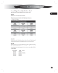
specs & maintenance
General Specification, Chassis
Specifications are for standard equipment, unless otherwise stated.
995
Alternator
200 Amp Bosch, 12 Volt, High-Output (standard).
185, 270 or 320 amp Leece Neville, 12 Volt, High-Output (optional) on:
All American FE Alternator Output @ Idle
200 amp Bosch (standard)
engine
cold (25c)
Cummins ISB
158 amps
185 amp Leece Neville (optional)
engine
cold (25c)
Cummins ISB
158 amps
270 amp Leece Neville (optional)
engine
cold (25c)
Cummins ISB
180 amps
320 amp Leece Neville (optional)
engine
cold (25c)
Cummins ISB
225 amps
hot (80c)
135 amps
hot (93c)
135 amps
hot (93c)
160 amps
hot (93c)
170 amps
Axle, Front
The front axle model is Hendrickson Steertek, with a Gross Axle Weight Rating of
13,200 lbs. capacity. Petroleum oil bearing lubrication and windowed hubcaps.
Hendrickson Model
SteerTek
SteerTek
SteerTek
SteerTek
GAWR
13,200 lbs.
13,200 lbs.
14,600 lbs.
14,600 lbs.
Details
4.25” Drop. Standard.
5.36” Drop
4.25” Drop
5.36” Drop
Axle, Rear
Meritor single reduction speed with synthetic bearing lubrication. Standard model is
RS21-145; 21,000 lb GAWR; 5.29:1 reduction ratio. All American FE may be equipped
with optional models depending upon GVWR and reduction ratio, suspension, and/
or brake options:
Meritor Model
RS19-144
RS21-145
RC23-160
RS23-160
GAWR
19,000 lbs.
21,000 lbs.
23,000 lbs.
23,000 lbs.
Details
Standard.
L
SERVICE MANUAL
996
Batteries
Three 12V/3375 CCA combined. 4/0 gauge battery cables are included. Battery cables positive and negative are loomed complete from terminal end to terminal end.
Enclosed in large locking heavy duty battery compartment.
Braking System
Service Brakes, Hydraulic. Both front and rear systems have 15” diameter x 1.438”
thick rotor, Meritor Quadraulic hydraulic brakes at all wheels. 70MM dual system 4
pistons per caliper. Self-adjusting design. Meritor ABS.
Emergency/Parking (Units with Hydraulic Brakes). Standard park brake, installed
on All American Forward Engine buses with hydraulic brakes, is an internal expanding, transmission mounted, 9” diameter x 3” wide, cable-actuated assembly, operated by a foot control lever at the driver’s left.
Service Brakes, Air. Meritor air actuated drum brakes are optional on most All American Forward Engine units, and are required by certain engine options and/or GVWRs.
(See Engine for more info.) All American Forward Engine units equipped with air
brakes have 6” Meritor Q-Plus linings on front; and either 7” or 8.62” lining on rear,
depending upon GVRW.
Air Tanks. One dual compartment tank with 1,250 cu. in. for the wet tank and 1,250
cu. in. for the primary tank. One secondary tank with 1,760 cu. in. Two tanks with a
total of 4,260 cu. in.
Emergency/Parking (Units with Air Brakes). All American Forward Engine buses
equipped with air brakes employ dual-chamber air brakes in the rear, which incorporate a spring brake in the outer chamber.
Bumpers
Front and rear bumpers are die-formed, 12” high with 90° flanges, top and bottom.
Front. One-piece 3/16” thick steel plate with step holes for cleaning windshield.
Rear. One-piece 3/16” thick steel plate with 14” wraparound at corners and double
“A” frame bracing.
Controls
Electronic operated throttle, hydraulic brake pedal, foot applied parking brake with
warning light, transmission selector, dimmer switch, instrument panel rheostat-controlled lighting and key-type starter switch.
Cooling System
Engine. Charge air and down-flow radiator mounted in tandem at vehicle front.
25” dia. nylon cooling fan with nine blades equipped with a fully-on or fully-off electromagnetic fan clutch driven by polyvee fan belt with spring loaded tensioner. Fan
controlled by engine ECM. Black rubber coolant hose with constant torque clamps.
Transmission. Transmission fluid cooled by 2100 BTU/minute heat exchanger external to radiator. Long-life Cool-Guard coolant mix provides anti-freeze protection to
-34° F.
L
Specs & Maintenance
Drive Line
Spicer SPL 70 or SPL 100 with protective guard around shaft.
Engine
Forward Engine All Americans are built with ISB-07 engines. Includes electric fan
clutch. Optional 500W / 120V AC internal engine block heater (serves as a heater
start aid). Includes a power cord.
997
All American Forward Engine Cummins ISB-07 Configurations
Engine
Horsepower @ RPM
Torque @ RPM
Transmission
Cummins ISB-07
200/520 (standard)
200@2300
(2600 Governed)
520 ft lb @1600
Allison PTS 2500
Cummins ISB-07
220/520
220@2300
(2600 Governed)
520 ft lb @1600
Allison PTS 2500
Cummins ISB-07
240/620
240@2300
(2600 Governed)
620 ft lb @1600
Allison PTS 2500 w/
SEM or
Allison PTS 3000
Cummins ISB-07
260/620
260@2400
(2600 Governed)
620 ft lb @1600
Allison PTS 2500 w/
SEM or
Allison PTS 3000
Cummins ISB-07
280/660
280@2300
(2600 Governed)
660 ft lb @1600
Allison PTS 2500 w/
SEM or
Allison PTS 3000
Exhaust
Stainless steel muffler. 4” O.D. 16 gauge aluminized steel tailpipe exits ahead of rear
axle, road side, except on 141” and 169” wheelbases. Wide band exhaust clamps used
at all joints.
Frame
Main Frame. Dual “C” channels, 9.63” high with 3” flanges made of .25 thick, 50,000
PSI steel, Section Modulus = 10.1 in.cu.
Sub-Frame. Dual “C” channels, 9” high with 2 3/8” flanges made of .25 thick, 50,000
PSI steel, Section Modulus = 8.4 in.cu.
Fasteners. All permanent fixtures on frame are attached with hi-tensile strength
Huck-Spin fasteners with swaged lock nuts.
Fuel System
60 gallon capacity standard. 100 gallon capacity (available only with: 190, 211, 232
wheelbase). Aluminized steel safety tank mounted between frame rails. Includes a
sender inspection plate and right hand fill opening with spring loaded locking door.
Primary fuel filter, is a Racor, 490 with primer pump. Filter provides a 10 micron, 90
GPH, heated, with water in fuel sensor for Cummins ISB-07.
L
SERVICE MANUAL
998
Horn
Electrical dual with non-glare horn button emblem.
Backing Safety Horn (Optional). Activated whenever the bus is shifted into reverse.
Sounds between 87 and 112 db, automatically adjusting itself depending on the ambient noise level in the proximity of the alarm
Instruments
Gauges. Speedometer with English major and metric minor; seven digit Odometer;
resettable Trip Odometer; Tachometer; Oil Pressure; Voltmeter; Fuel Level; Coolant
Temperature; Front Brake Pressure; Rear Brake Pressure; digital Clock; Panel Dimmer
slide; Ammeter. Gauges have automatic self-test at power up. Needles sweep while
display indicates “TEST”.
LED Telltale Warnings / Indicators. Right and left directional (green); high beam indicator (blue); Service Brake Applied (red); Park Brake Applied (red); ABS Active (amber); Stop Engine (red); Service Engine Soon (amber); Check Transmission (Red); Low
Coolant Level (Amber).
Steering
Full power Ross THP-60 integral unit with 18.2 to 1 ratio; with gear driven hydraulic
pump. Tilt telescoping steering column with 18” diameter, four-spoke, padded steering wheel.
Suspension, Front
Front Spring Suspension (Standard). Hendrickson SofTek.13,200 lb rated. 4” x 60”,
two-leaf parabolic taper springs, maintenance free rubber bushings each end at
shackle bracket. 1.38” diameter bore double-action Sachs shock absorbers. Antisplay clip to maintain spring stack alignment. Anti-noise urethane wear pads between spring leaves at ends softens ride.
Front Air Suspension (Optional). Hendrickson AirTek. 14,600 lb rated. Vertical load
carried by air spring, lateral load carried by single 4” x 60” steel spring which includes
front safety wrap leaf for school bus applications. Maintenance free rubber bushings
each end at shackle bracket. 1.38” diameter bore double-action Sachs shock absorbers with long-life bonded rubber bushings. Leveling valves to maintain ride height
at all load conditions.
Suspension, Rear
Rear Spring Suspension (Standard). Drive axle spring suspension system with 3”
x 52” flat two-stage, variable rate, 13-leaf slipper springs, Capacity rating varies depending upon wheelbase. Maintenance free, rubber bushed radius leaf permits axle
adjustment for dog tracking. 1.38” diameter bore double-action Sachs shock absorbers with long-life bonded rubber bushings.
Rear Air Suspension (Optional). Hendrickson Comfort Air. 23,000 lb rated, trailing
arm design with 2 heavy-duty rolling lobe air springs. Sachs 1.38” diameter bore
shock absorbers, with long-life bonded rubber bushings. Single height control leveling valve to maintain ride height at all load conditions.
L
Specs & Maintenance
Tires
Goodyear 10R 22.5 LRG, G149 RSA.
Tow Hooks
Two front and rear, tow hooks are frame mounted.
999
Transmission
Allison PTS 2500, and 3000 Series transmission, 5 Forward speeds- 1 reverse. 33,000
lbs GVW. Synthetic transmission fluid is standard.
Wheels
Hub Piloted steel 10 stud disc wheels, single front, dual rear, 22.5 x 8.25 rims.
L
SERVICE MANUAL
General Specification, Body
1000
Access Panels
Interior. Hinged access door on engine hood for access for routine daily engine inspection & service.
Exterior. All access panels are standard non locking. Keyed locked latches optional.
Electrical Terminals. 27.5” x 21.75” hinged door located exterior below driver’s windows for access to body electrical junction, terminals and circuit breakers. Door has
retainer to hold in open position. Chassis PDU, 27.5” x 15” hinged door located exterior below body electrical junction, terminals and circuit breakers.
Front Grill. Lifts upward for service access.
Right Front and Left Front. Hinged doors provide access to heater air intake screen,
air restriction indicator, wiper motors, windshield washer reservoir, power steering
reservoir and hydraulic master cylinder reservoir.
Compartments
Battery. Enclosed compartment 23.5” x 15.5” with rolling tray. Includes two retaining
pins with cable to secure the tray in a closed position. Hinged door with recessed
locking Paddle Handle latch. Located on left side behind front wheel well.
Emergency. Provides key locking compartment for storing certain emergency equipment located in upper front. Key lock is equipped with switch and wired to buzzer to
indicate that compartment is locked when ignition is turned on.
Glove Box. 11” x 6 1/2” door above windshield on right side with door and latch.
Doors
Rear Center Emergency Door. 42” wide x 58.25” high opening. Latching mechanism
includes a single-point bar lock with inside handle and guard, and an outside 6” black
handle. Door includes upper and lower tempered green tinted safety glass. Doors
are identified as “EMERGENCY DOOR”, 2” black letters, above the door, on the outside
of the bus. Includes Emergency door arrows inside and outside 6” long x 3/4” wide
black arrow on the emergency door near the handles to indicate direction of turn
for opening. On the outside, arrow points up and approximately 45° inboard of door;
inside, the arrow points up. Arrows are in addition to standard ”OPERATING INSTRUCTIONS” decal. A DOT warning buzzer activated by movement of the door latching
mechanism is included. A 5” black fire-block upholstery header pad is included. A
telescopic prop support attached to the top inside of the emergency door to hold
it open at approx. 95°. Slide-bolt security latch prevents door from being opened
from the outside when engaged. Bolt is connected to an interlock assembly which
prevents engine starting when door is locked. If the lock is activated after the engine
is running, an audible alarm is sounded in the driver’s area.
Outward Opening Entrance Door, Manual Operation. Two panels open outward
and close to seal against outside edge of lower step. Includes laminated green tinted
glass. Ball bearing suspended for ease of operation and wear resistance. A Manual
locking mechanism is built into the forward outward opening door assembly. This
will disconnect the door from the manual control rod, and allow the door to be
L
Specs & Maintenance
opened from the outside of the bus. The latch located in the front door panel and
accessible from outside the bus is lockable with the LL25 key. 4” wide black fire-block
upholstery header pad over the door opening inside the bus. Stainless steel assist rail
at the rear of the stepwell. Manual over-center control with an automatic latching
device built into the handle for holding the door closed. Driver manually disengages
the latch as the door is opened. Pivot bearings are oil-impregnated bronze.
1001
Electrical
Power Socket, Accessory With Cap. Provides 12 volt power socket for connecting
electrical accessories such as cellular phones, CB radios, etc. Only one per vehicle.
Fans
Driver’s Auxilliary Fans. 6” fan mounted to wire molding, located in the upper left,
above driver’s window. 6” fan mounted to windshield header, center of body.
Floor
Aisle. 3/16” thick ribbed gray rubber in aisles and at entrance aisle area. Aluminum
Aisle trim over joint in floor covering, full length of body.
Underseats. 1/8” thick smooth gray rubber. Galvanized steel cove molding at wall.
Wheelhousing. Molded black smooth rubber with galvanized steel trim.
Underfloor. 5/8” AB marine grade plywood, attached with screws.
Headroom
Full 78”, over floor covering and 5/8” plywood floor, measured at center aisle.
Heater/defroster
Black rubber heater hoses with constant torque clamps at all joints. Includes all heater hoses and hose clamps within the body heater system.
Front Heater/Defroster. 90,000 BTU with washable air filter. Driver selects air flow up
to 100% for defrosting windshield, driver’s window and entrance door as conditions
require.
(Optional) Auxiliary. 12,000 BTU, two speed heater under driver seat left side. Dual
ball type, heater cut-off valves isolate system from engine and radiator when necessary.
Insulation
The roof, sides, front and rear (including corners & bows) are insulated with 1 1/2” thick
material providing an “R” value of 5.75. Driver’s left hand close-out panel is insulated
inside and outside.
Lettering
3M Diamond Grade “SCHOOL BUS” 8” black vinyl letters on yellow reflective tape on
roof caps, front and rear. BLBS lettering and Bus numbers.
L
SERVICE MANUAL
1002
Lights
Back-Up. Two 4” clear right and left rear.
Clearance. Two LED amber front and two LED red rear single. Switch operates clearance, cluster and side marker lights.
Cluster. Three amber front and three red rear.
Daytime Running. Head lamps, tail, license plate, parking, clearance & marker lights
activated when engine is running.
Directionals. 7” Front and rear, two plain amber front, two amber rear. Sealed, shock
mounted, side directionals mounted at front belt line area
Dome. 15 Candlepower. Two rows equally spaced in wire molding. Separate switch
to control the last two dome lights of the dual row. Driver’s dome light activated with
separate switch.
Headlights. 7” Round, halogen with replaceable bulb. Alarm recognition when headlights are on and igntion is off.
Side Marker. 2 LED amber right and left intermediate side marker lights.
Stepwell.14 Candlepower. Wired to operate with ID lights with entrance door open.
Stop and Tail. Two combination lights, 4” right and left rear license panel in combination with 7” stop and tail lights with clear red lens.
Warning System. 8 light sequential system with optional dual hoods.
Mirrors, Exterior
All exterior mirrors will be heated. Heat is controlled by an on/off switch.
Crossview. A Mirror Lite “High Definition” crossview mirror system offers a revolutionary new mirror lens design for increased pedestrian safety and driver visual confidence. The crossview mirror system is comprised of a 10.8” x 12.5” elliptical mirror.
The mirror mounting posts are attached to the front cowls, and feature a breakaway
pivot to reduce damage in the event of accidental contact. The crossview mirror system allows for viewing all areas along the front and sides of the bus which are not
visible by direct view.
Rearview. The Mirror Lite “Viewmaster” non-detent rearview mirror system is designed to provide a view of the roadway to the rear, as well as a view of the ground
along both sides. The Rearview mirror system is comprised of a hand adjustable 7.75”
x 10” Flat mirror lens tray, hand adjustable 7.75” x 7.75” Pie-shaped convex mirrors
and mirror glass, lefthand grab handle type arm for viewing mirror throgh driver’s
window and righthand non-breakaway overhead type arm for viewing mirrors
through windshield.
Mirrors. Interior
Rearview. 6” x 30” with 3/16” clear safety glass laminated to steel backing plate. Mirror
has 1 3/4” radius rounded corners. Perimeter of mirror is edged with 5/8” diameter rubber padding. The interior rearview mirror is installed above the seated driver on the
front upper inner panel, and is designed to provide a clear view of the interior of the
vehicle and of the roadway to the rear.
L
Specs & Maintenance
Mud Flaps
Front. Metal guard forward of front axle; left side. Mudflaps to full length, installed
behind front wheels. Black rubber fenders.
Rear. 23 x 30” mudflaps; both sides (without logo and with extensions included).
Black rubber fenders.
1003
Paint
Exterior. National school bus yellow with black trim and black bumpers. OEM, heat
cured, polyurethane.
Interior. Astro White, hot sprayed-on baked enamel, except aluminized inner side
panels. Seat frames, heaters and trim are Black, switch consoles and dash medium
gray.
Rust Proofing. Body parts thoroughly rust-proofed after fabrication and before assembly.
Undercoat. Underside of body floor, skirt and wheelhousings thoroughly undercoated prior to body mount to insure best coverage and maximum corrosion resistance.
Undercoat material offers optimum corrosion protection.
Panels, Exterior
Body. Outside side panels are constructed of 20 gauge smooth steel. Side panels extend from below the side windows to a distance of 19 3/4” below the floor. Rear corner
panels are constructed of 20 gauge steel. Front cowl panels are 20 gauge steel.
Roof. The front roof cap is formed from 18 gauge steel. The rear roof cap is formed
from 20 gauge steel. Roof sheets are constructed of 20 gauge steel and span the
entire width of the bus (window header to window header). Roof sheets include an
embossed rain visor over side windows.
Floor. 14 Gauge steel zinc coated steel.
Panels, Interior
A removable 18 gauge steel front upper panel provides access to the front roof cap
area. Wire molding over window provides easy access to body wiring harness. Textured aluminized fully hemmed steel inside side panels extend from the window sill
down to the floor gusset seat ledge, for the entire length of the body on both left and
right sides. Headlining panels, spanning the entire width of the bus (window header
to window header), are constructed of 22 gauge steel and are double-hemmed to
provide additional joint strength.
Radio
AM/FM/PA/CD, console mounted with 8 deluxe speaker system. Wiring for two way
radio system. (Two way radio is not included.)
L
SERVICE MANUAL
1004
Reflectors
Standard reflectors include:
• Two 3” Diamond grade adhesive backed amber mounted on side of body near
front.
• Two 3” Diamond grade adhesive backed red mounted on side of body near
rear.
• Two 3” Diamond grade adhesive backed red, mounted on rear of body.
• Two 3” Diamond grade adhesive backed amber right and left intermediate
side reflectors.
Reflective Tape. 3M Diamond Grade. 1” minimum width strip surrounds each emergency exit, 1 3/4” wide rear structure, and 2” wide strip on each side of unit at approximately floor level. Front and rear roof cap, with Black 8” “SCHOOL BUS” lettering.
Canada. 1” wide strip of yellow reflective vinyl on each side of the bus, above the
passenger windows. Vertical 1” strips of yellow reflective vinyl at both the rear bow
and front corner post, both sides of the bus.
Rubrails
Four double-ribbed 16 gauge steel applied rubrails are installed along both sides of
the body. The rubrails are installed as follows: One below side windows; one at seat
(passenger) level; one near the floor level; one at the bottom of the skirt. The window
rail, seat rail and floor rail extends from the front bow to the rear corner radius.
Safety Equipment
Triangular Warning Device floor mounted. Seat belt cutter included as standard
equipment when lift door is ordered.
Seats
Driver’s. National Driver’s Seat. This seat has 4” height adjustment by fingertip controls, 7” fore and aft seat slides, recline angle infinitely adjustable, mechanical lumbar
adjustment. Seat covering is gray colored fire block vinyl with pebble-top grain. A
3-point single bar lock seatbelt with adjustable pillar loops provides approximately 7
1/2” of vertical adjustment at the shoulder belt top mount. Single emergency locking
retractor includes male locking bar tongue on the left retracting side.
Passenger Seat Upholstery. All Passenger seats are optional and will be upholstered
in Fire Block vinyl, solid gray.
Stepwell
Three-step, 24 3/4” depth stainless steel. Black ribbed step treads non-abrasive with
white nosing. 3” white ribbed rubber wear plate is located at the floor level step of
the entrance door. Includes a stainless steel assist rail at the rear of stepwell.
L
Specs & Maintenance
Stop Arm
An electric operated High Intensity Reflective octagonal stop arm, red with a white
border and 6” high lettering. “STOP” or “ARRETT” on both sides. Includes red incandescent lights over and under the word “STOP” visible from both sides.
1005
Sun Visor
Transparent dark green tint 6.5” x 30” smooth edge plastic. Located in front of driver.
Adjustable vertically on two arms pivoted at ends of visor and at anchor points on
windshield header.
Switch Panel
Mounted left and right of driver with rocker-type self illuminated switches for electrical equipment. Brightness of illumination is controlled by a separate dimmer switch
located in the left switch panel.
Ventilation
Air Intake. Heater intake on right front below windshield level is electrically controlled. Manual driver’s fresh air vent on left by driver’s feet.
Static Vent. Static non-closing type in front roof.
Windows
Driver’s. Double sliding aluminum sash with security fastener for locking both sashes, clear tempered glass.
Side. 12” Split Sash, tempered clear glass in aluminum frame, 12” clear opening when
lowered.
Rear Vision. Clear laminated glass bonded into structure.
Windshield
Two piece curved tinted laminated safety glass bonded into the structure.
Windshield Wipers
Electric, intermittent single switch, pantograph type, bottom mounted with remote
control, non-glare arms and blades. Electric windshield washer with hard plastic
4 quart capacity reservoir located behind right front access door, washer outlets
mounted on wiper arms.
Wiring
Color- and number-coded in molding above windows for access to harness without
removing windows. Body wiring protected by automatic resetting circuit breakers,
located in easy access exterior wire terminal junction under driver’s window.
L
SERVICE MANUAL
Dimensions
1006
The dimensions shown exclude exterior mirrors, marker and signal lights, bumpers,
fender skirts, washers, wipers, and frames and rub rail; and are taken under static
conditions at design height. Overall maximum height varies from 114” to 125” depending upon choice of tires, suspension system, and body model. Add 3” for roof
vents. Rear bumper adds 1.25” to overall body length. Front bumper adds 2” to overall body length.
Width:
Interior Width:
Height:
Height, with Air Conditioning:
Front Overhang:
Skirt Length:
Interior Headroom:
Front Door:
Rear Emergency Door:
Wheel Cut:
Tire Size:
96”
90 3/4”
123”-126”
Add 16”
94.48”
19 3/4”
78”
32” wide, 81” high
43 3/4” wide, 62” high
50° (nominal)
Goodyear 10R 22.5 LRG, G149 RSA
Dimensions & Payload Weight (standard equipment)
wheelbase
body
model
capacity
141”
169”
190”
190”
211”
211”
232”
232”
D3FE2903
D3FE3107
D3FE3406
D3FE3508
D3FE3603
D3FE3800
D3FE3909
D3FE4004
54
60
72
72
72
78
84
84
payload
curb
weight
total
weight
overall
length
6630
7350
8790
8790
8790
9510
10230
10230
17,907
18,420
18,813
19,142
19,440
20,052
20,427
20,916
24,537
25,770
27,603
27,932
28,230
29,562
30,657
31,146
353.93
381.93
416.93
430.93
437.93
458.93
479.93
486.93
turn
turn
radius
radius
curb-to- wall-torear
overhang
curb
wall
118.45
118.45
132.45
146.45
132.45
153.45
153.45
160.45
22’
23.7’
26.5’
26.5’
29.5’
29.5’
31.1’
31.1’
26.1’
28.3’
31’
31’
34.1’
34.1’
35.6’
35.6’
Pupil weight @ 120 lb each. Driver @ 150 lb.
Approximate curb & total weights are based on standard equipment units. Optional equipment may significantly increase these estimated weights.
L
Specs & Maintenance
Fastener Grades
The following information defines chassis fastener grades to be used for the installation of various items on the Blue Bird chassis. The fastener grades shown are minimums, and the information applies to Blue Bird installed fasteners only. It does not
apply to vendor supplied or installed fasteners, except where noted. Chassis fasteners not specified below must be grade 2 at a minimum. The grade of the hexnut used
must be equal to the grade of the bolt to which it is assembled.
1007
General Torque Procedure
Grade 8 and Grade 5 fasteners must be tightened to the recommended torque values
listed in the Designated Fastener table. When the washer is on the threaded (hex nut)
side, hold the bolt head and tighten the hex nut while reading the torque. Observe
the torque to ensure it is in the specified range. It is usual practice to always torque
the nut and not the bolt wherever possible. When there are washers on both sides of
the bolt (capscrew), or it is assembled into a threaded hole, torque the bolt head to
the specified value. Do not lubricate the components when applying torque.
L
SERVICE MANUAL
1008
Designated Fasteners Torque Chart (Plated Fasteners) U.S. Standards
SAE grade 2 (ft-lbs)
SAE grade 5 (ft-lbs)
size
Min
Max
Min
Max
1/4”–20
3
4
5
6
1/4” –28
4
5
6
7
5/16”–18
7
8
12
13
5/16”–24
8
13
17
19
3/8”–16
13
15
17
19
3/8 ”–24
15
17
23
26
7/16 ”–14
21
24
33
37
7/16 ”–20
24
27
37
41
1/2” –13
33
37
50
57
1/2 ”–20
37
41
57
64
9/16”–12
47
53
73
82
9/16 ”–18
53
59
82
91
5/8 ”–11
63
73
106
112
5/8 ”–18
73
83
112
128
3/4 ”–10
116
129
177
200
3/4 ” –16
129
144
200
223
7/8 ”–9
112
125
289
322
7/8”–14
125
138
322
355
1”–8
188
437
483
1”–12
188
205
483
529
1”–14
205
210
529
541
Designated Metric Class 10.9
torque (ft-lbs)
size
Min
Max
M4
2.6
2.9
M5
5
6
M6
9
10
M8
22
25
M10
53
58
M12
75
83
M14
1210
133
M16
176
196
M20
302
336
M24
598
664
L
SAE grade 8 (ft-lbs)
Min
Max
8
9
9
10
16
18
24
27
24
27
33
37
46
52
52
58
70
80
80
90
101
115
115
129
138
159
159
180
250
282
282
315
407
454
454
501
618
682
682
746
746
764
Specs & Maintenance
Non Designated Fasteners Torque Chart (Plated Fasteners) U.S. Standards
SAE grade 2 (ft-lbs)
SAE grade 5 (ft-lbs)
size
Min
Max
Min
Max
1/4”–20
2
4
4
6
1/4”–28
3
5
5
7
5/16”–18
6
8
9
13
5/16”–24
7
9
10
14
3/8”–16
10
15
16
23
3/8”–24
12
17
18
26
7/16” –14
17
24
25
37
7/16”–20
19
27
28
41
1/2” –13
25
37
40
57
1/2” –20
28
41
44
64
9/16”–12
47
53
73
82
9/16”–18
53
59
82
91
5/8”–11
63
73
106
112
5/8”–18
73
83
112
128
3/4”–10
116
129
177
200
3/4”–16
129
144
200
223
7/8”–9
112
125
289
322
7/8 ”–14
125
138
322
355
1”–8
188
437
483
1”–12
188
205
483
529
1”–14
205
210
529
541
SAE grade 8 (ft-lbs)
Min
Max
6
9
7
10
12
18
14
20
23
33
26
37
46
52
52
58
70
80
70
90
101
115
115
129
138
159
159
180
250
282
282
315
407
454
454
501
618
682
682
746
746
764
1009
Non Designated Metric Class 10.9
torque (ft-lbs)
size
Min
Max
M4
2.0
2.9
M5
4.2
6
M6
7
10
M8
17
25
M10
33
58
M12
58
83
M14
93
133
M16
137
196
M20
235
336
M24
465
664
L
SERVICE MANUAL
Service Precautions
1010
This section proscribes safe working practices which must be followed in order to
minimize the risk of personal injury and/or damage to the vehicle. Additional Warnings and Cautions appear throughout this manual.
Also follow all warnings and cautions printed in the various manuals from component manufacturers, included in this manual as chapter Appendixes.
Whenever Working Under the Bus:
Never move under a bus supported only by a hydraulic jack. Use only proper jackstands or lifts. Always check lifting equipment thoroughly to verify proper working
condition before each use. Ensure that the lifting equipment is rated for lifting the
weight of the bus. Ensure that the surface under all jacks, stands, or lifts is hard, level,
and secure enough to support the weight of the bus concentrated on the footprint
of the jack. Chock all wheels to prevent rolling in either direction. Disconnect battery
cables to ensure the vehicle cannot be started.
About Modifications:
School buses are built in conformance to several levels of stringent governmental
regulations. Any user-performed modification of the bus may potentially result in a
non-conformance. For this reason, it is Blue Bird’s policy that end users should not
perform any equipment modifications to the bus. Contact your Athorized Blue Bird
Dealer for advice and consultation before adding any electrical accessories or nonstandard mechanical equipment.
Whenever Working Around Moving Parts:
Use extreme caution to avoid accidental entaglement. Do not wear loose clothing.
Remove all jewelry including watches and rings. Securely cover long hair. Wear eye,
hearing, and respiratory protection.
Whenever Working Inside the Engine Compartment:
Disconnect batteries to prevent accidental engine starting. Exercise extreme caution around hot components, and wear sufficiently protective clothing. Whenever
possible, allow components to cool completely before working. Be mindful of any
system which operates under pressure, and ensure that pressure is released before
working on that system.
When closed system components (such as those associated with the fuel system,
cooling system, or charge air system) have been removed, always take appropriate
measures to prevent contamination of the system by dust, dirt, or debris.
Replacing Fasteners
Do not re-use fasteners in high-torque locations. Replace with new fasteners of appropriate hardness grade.
L
Specs & Maintenance
Performing Structural Repairs:
Welding. Modern school buses are equipped with sensitive electronic equipment
such as the multiplex system and the ECUs of engine, transmission, and ABS brakes.
Such components can be permanently damaged by current fluctuations. In addition
to the welding precautions you would normally take to isolate components which
may be damaged by heat, the repair technician must also bear in mind the potential
for expensive damage to electronic systems. It is highly recommended that the multiplex Main Bus Controller and other such electronic control units be disconnected
before performing any welding anywhere on the body or chassis.
1011
Whenever Rendering Roadside Assistance:
Take measures to ensure the safety of passengers first. Move passengers away from
the disabled bus to a safe location in an organized fashion. Use the roadside emergency markers to clearly warn traffic of the hazard. Call for help and alternate passenger pick-up immediately. If at all possible, avoid performing service procedures
roadside, and instead have the bus towed to a proper and safe service facility.
Hazardous Materials
Vehicle fluids, including engine coolant, transmission fluid, engine oil and power
steering fluid, are hazardous to the environment and to the individual performing
maintenance and repair on the vehicle. The handling, storage, and disposal of these
fluids are subject to government regulation. Read and strictly follow the warnings
and instructions on the labels of all fluids and compounds.
The anti-freeze in engine coolant is Ethylene Glycol. This is a skin, eye and respiratory
irritant, and is toxic to humans and animals.
Certain other materials, such as plastics, rubber compounds, solvents and paints,
are also considered environmental hazards. Always exercise caution to protect your
health and the environment when working with, or disposing of, any chemically active material or compound, including cleaning materials.
Protective Gear
Always wear proper eye protection and other required personal protective equipment to help prevent personal injury when performing vehicle maintenance, repair,
or service. These include, but are not limited to:
• Skin protection. Long sleeves, appropriate gloves, an appropriate apron, etc.
• Eye protection: Safety glasses, a facemask, serviceable eye wash equipment,
etc.
• Respiratory protection: A filter mask appropriate for the material being used,
properly ventilated work area, emergency breathing aids, etc.
• Hearing protection: Earplugs, earmuffs, etc.
L
SERVICE MANUAL
Jacking and Towing
1012
Jack Points
Front Jack Point
[WARNING] Proper jacking procedures and basic safety measures must be observed to ensure the safety of personnel while
working under the bus. Always check the serviceability of any lifting equipment prior to use. Ensure that the lifting device is of sufficient strength to handle the bus, and that the surface provides
the necessary firmness to support the weight of the bus concentrated on the footprint of the jack. Never move under a bus supported only by a hydraulic jack.
1. Park the bus on a flat, level surface of sufficient firmness to support the jack.
Rear Jack Point
2. Chock the wheels in both directions.
[WARNING] The parking brake functionality relies on the rear
wheels remaining in contact with the surface the bus is parked on.
If one or both wheels are lifted off the surface the park brake will
not function and the bus may move resulting in potential bodily
harm or death.
3. Use only jacks and jack stands of sufficient capacity to support
the bus. Following the jack manufacturer’s recommendations,
place the jack securely under the axle at the spring or suspension beam, nearest the tire/wheel to be repaired.
4. Jack the bus only to the height necessary to service.
5. Support the bus with blocks or jack stands under the frame rails.
Towing
If the bus is towed with the rear wheels on the road, the driveshaft must be prevented from turning in order to avoid possible damage to the automatic transmission.
This is accomplished by removing the rear axle shafts, and covering their openings
with caps to prevent rear axle lubricant spillage.
Also, on All American’s equipped with air brakes, if full normal air pressure is not
present in the air system, the spring brakes must be mechanically caged to prevent
their engagement.
1. Apply the parking brake and chock the wheels while preparing the vehicle
for towing.
L
Specs & Maintenance
2. Remove the stud nuts and washers from the center hub.
3. To loosen the tapered dowels which surround each stud, use a 1.5” diameter
brass drift and 5-6 lb hammer. Hold the brass drift against the center of the
axle shaft flange, inside the round driving lugs. Firmly striking the end of the
brass drift with the hammer will dislodge the tapered dowels.
1013
Brass Drift
[CAUTION] Do not use a chisel or wedge to loosen the axle shaft and tapered
dowels. Doing so can damage the axle shaft, gasket, seal, or axle hub.
4. Mark the axle shaft so that it can easily be identified for reinstallation on the
side of the axle from which it is removed. Carefully remove the axle shaft, taking measures to catch the axle lubricant which may spill. Install a cover plate
over the open end of the hub to prevent dirt contamination and lubricant
spillage during towing.
5. Repeat the above procedure to remove the other axle shaft.
6.If the bus is equipped with air brakes, and if full working air pressure is not
present in the system, the spring brakes must be mechanically caged before
the vehicle can be towed. Proceed as follows:
[WARNING] Caging the spring brakes disables the parking brake. Ensure that
the bus is completely secured against rolling by wheel chocks before caging the
spring brakes.
6.1 On each of the rear combination brake chambers, a special release
stud tool is carried in a storage socket cast into the body of the chamber. Remove the nut and washer from the end of the release stud tool,
and remove the tool from its socket.
6.2 Remove the rubber dust cap from the access hole in the upper end of
the spring brake chamber. Insert the toggle
end of the release stud tool into the access
hole. Be sure that the tapered end of the tool
has entered the hole in the piston inside the
chamber. Insert the tool until it bottoms.
6.3 Rotate the release stud tool a quarter turn
clockwise and pull outward, to engage the
toggle end with the piston. While holding
the bolt in its engaged position, install the
washer and nut onto the end of the tool.
Turn the nut down against the flat washer
until finger tight.
L
SERVICE MANUAL
1014
6.4 Using a 3/4” hand wrench, (do not use an impact-type wrench), turn
the release nut clockwise until the internal spring is fully caged.
6.5 Repeat the procedure for the spring brake chamber on the opposite side of the bus. The spring brakes are now released, having their
springs compressed by the release bolts.
7. With the axle shafts removed and air spring brakes caged, the bus is prepared for towing. The All American may be equipped with optional tow
hooks, located just inside the access openings of the front and/or rear bumper. Appendix 1 of the Front Axle & Suspension chapter contains additional
information about towing procedure.
[WARNING] The tow hooks are
designed for horizontal pulling
only; not for lifting. Never attempt
to lift the bus by the tow hooks.
Front Tow Hooks
Front Tow Hooks
Rear Tow Hooks
Rear Tow Hooks
L
Specs & Maintenance
Fluids & Filters
Fluids & Filters, Forward Engine
Fluid
Type
Engine Oil
Engine Coolant
High-Quality SAE 15W-40
heavy duty engine oil, such as
Valvoline Premium Blue
Cummins,Fleetguard
ES Compleat
50/50 premix
(standard only)
Capacity
Filter
Engine, Cummins ISB
21.4 Quarts
(including filter)
19 Quarts
(without filter change)
Comments
1015
See your Cummins ISB Owner’s Manual for more
details.
Cummins equipped buses may have optional extendedlife coolant installed. Never mix different coolant colors,
6.8 Gallons
BB 0064641 types, or brands. See Engine Cooling System chapter
(excluding heater system) Wix 24070
for details..
Transmission
Transmission Fluid
Transynd™
7.4 Quarts (7 liters)
Transmission refill capacity is substantially less than
the initial fill because some fluid remains in the
BB 0033381
transmission cavities after draining.
Rear Axle
Axle Oil (RS19-144)
Axle Oil (RS21-145)
33.3 pints (15.2 liters)
Hypoid Gear Oil
Axle Oil (RS23-160)
See Rear Axle Viscosity Chart for appropriate viscosity.
33.3 pints (15.2 liters)
39.5 pints (18.7 liters)
Front Axle
Front Axle Grease
Chevron Dura Lith Grease
EP NLGI 2
Front Axle Oil
Chevron RPM Synthetic Transmission Fluid SAE 50
2.1 pounds
4 pints (1.9 liters)
Brake System
Brake Fluid
DOT 3
DOT 3 and DOT 5 must not be mixed. If brake system
becomes contaminated with DOT 5, the system must
Fluid
be flushed, and major components may require
BB 0067254
replacement.
Brake Interlock
DOT 5
Fluid
BB 1940881
On units with hydraulic brakes and brake interlock
feature*
Hydraulic Steering
Dexron III™
BB 0020138
BB 0066221
On units with air brakes.
On units with air brakes.
Hydraulic System
3 quarts (approximate)
Pneumatic System
AD-9 Air Dryer Element
AD-IP Air Dryer Element
Fuel System
Fuel Filter / Water Separator
BB 1967009
Other
Windshield Washer Fluid
1.05 gallons
L
SERVICE MANUAL
1016
L
Rear Axle Viscosity /Temperature Chart
Meritor Lubricant Specification
Description
Cross Reference
Minimum Outside Temperature Maximum Outside Temperature
0-76-A
Hypoid Gear Oil
GL-5, S.A.E. 85W/140
+10° F (-12.2° C)
*
0-76-B
Hypoid Gear Oil
GL-5, S.A.E. 80W/140
-15° F (-26.1° C)
*
0-76-D
Hypoid Gear Oil
GL-5, S.A.E. 80W/90
-15° F (-26.1° C)
*
0-76-E
Hypoid Gear Oil
GL-5, S.A.E. 75W/90
-40° F (-40° C)
*
0-76-J
Hypoid Gear Oil
GL-5, S.A.E. 75W
-40° F (-40° C)
+35° F (+1.6° C)
0-76-L
Hypoid Gear Oil
GL-5, S.A.E. 75W/140
-40° F (-40° C)
*
* No upper limit on these temperatures. However, axle sump temperature must never exceed + 250° F (121° C ).
Specs & Maintenance
General Maintenance Schedules
The following charts list maintenance procedures which should be performed with
regularity. For convenience, some of these tables are also duplicated in their respective areas throughout the manual.
1017
About Service Intervals
The charts show recommended minimum service intervals. More frequent service
intervals should be considered if the vehicle is operated in extreme conditions such
as high humidity and/or dusty environments. Time intervals are shown in terms of
months or mileage. The correct interval is whichever is the first to occur.
Some components should be regularly inspected, but do not lend themselves to
universal intervals, because their normal service life is highly dependent upon local
conditions. For these components, any estimated interval would result in overservicing in some locales and underservicing in others. Such intervals are left to the
judgement of the local technican, and the service interval indicated is As Required. It
is important to understand that this designation should not be taken as an optional
inspection. Every item in the following tables should be considered mandatory, and
an As Required interval should be viewed as emphasizing the importance of the local service operation first determining, and then strictly adhering to, an appropriate
interval. Regardless of the interval determined appropriate, the operation must not
be overlooked.
Vendor-Supplied Maintenance Guidelines
The technician should bear in mind that many of the components which are installed
on a bus, are neither manufactured nor serviced by the bus manufacturer. Service
and Maintenance information more detailed than that presented in this manual may
be available from the component manufacturer, or may be included in the chapter
appendixes. Wherever practical and available, component-specific material from our
vendors has been included on the CD which accompanies this manual, and references to those documents are given in the maintenance charts.
Please be aware that these supplemental documents are provided as a courtesy,
and are reproduced in their entirity. Therefore, they may also include information on
other component models offered by the vendor, but not specifically applicable to the
Blue Bird bus. When referring to the appendixes documents, always check the model
of the component and be certain that you are using the applicable portions of the
appendix documents.
Also, some of the manufacturer-supplied component manuals contain rebuild
procedures. As a general rule, Blue Bird does not recommend rebuilding of components, especially in safety-critical systems such as air or hydraulic control valves. Blue
Bird strongly recommends component replacement over rebuild.
L
SERVICE MANUAL
Maintenance Task Schedule
1018
Ensure that the Safety Information, warnings and instructions are read and understood before operation or maintenance procedures are performed. Use whichever
interval listed (time, mileage, engine hours) occurs first. Engines operated in severe
operating conditions may require more frequent maintenance. See engine manufacturer’s specifications for more information.
First Month Then Every 3 Months or 3000 Miles
Cooling System
Inspect & Tighten Hose Clamps
Tighten radiator hose clamps to 90 in lb. Tighten heater
hose clamps to 45 in lb.
First 100 Miles Then Every 12,000 Miles
Tires & Wheels
Inspect & Tighten Lug Nuts
Torque to 450-500 ft lb with calibrated torque wrench. Do
not over-tighten. Do not lubricate nuts or studs. Operating
conditions may require more frequent checks.
First 1000 Miles Then Every 3 Months or 6000 Miles
Frame
Inspect & Tighten Body Tie Downs Body
Inspect for missing, damaged rubber pads. Tighten clamps
Tie Down Clamps
to 37–41 ft lb.
Inspect & Tighten Body Tie Downs Rear
Inspect for missing, damaged rubber pads. Tighten clamps
Tie Down Bolts
to 37–41 ft lb.
Inspect Front Rubber Isolators
Replace any worn isolators. Tighten bolts to 52-56 ft lbs.
First 1000 Miles Then Every 6 Months or 6000 Miles
Axle & Suspension, Front
Lubricate Parabolic Spring Suspension
NLGI #2 Grease.
Spring Pins
Axle & Suspension, Rear
Inspect Comfort Air Suspension Ride
Height
L
Shock length, eye-to-eye: 22.68" +/- 0.25"
Specs & Maintenance
First 1000 Miles Then Every 12 Months or 12,000 Miles
Heaters & Defrosters
Inspect Front Heater Hoses & Clamps
Inspect for evidence of leaks or deterioration. replace with
proper parts.
1019
First 5000 Miles Then Every 12 Months or 24,000 Miles
Transmission
Replace Transmission Sump Filter
First 5000 Miles Then Every 24 Months or 24,000 Miles
Transmission
Replace Transmission Main Fluid Filter
First 11,000 Miles Then Every 3 Months or 5000 Miles or 250 Engine Hours
Engine
Inspect All Belts
Inspect condition and tension of belt.
First 11,000 Miles Then Every 6 Months or 250 Engine Hours
Brakes
Replace Air Brakes Air Compressor Filter
First 11,000 Miles Then Every 6 Months or 5000 Miles
Cooling System
Inspect Charge Air Cooler
Inspect for clogging debris.
L
SERVICE MANUAL
As Specified by Engine Manufacturer
Cooling System
1020
Replace Coolant
See your Engine Ooperator's Manual. Use only premixed
coolant(s) approved by the engine manufacturer. Never
mix different types or brands of coolant.
Engine
Replace Oil & Filter
See Engine operators manual for oil and filter specifications
and maintenance interval.
Adjust Valves
See Engine manufacturer's Service Manual for interval.
As Specified by Transmission Manufacturer
Transmission
Adjust Transmission Shift Cable
L
See Transmission Chapter.
Specs & Maintenance
Every Day
Doors
Test Wheelchair Lift
Follow the manufacturers recommendations.
1021
Emergency Equipment
Inspect Fire Extinguisher Charge
Ensure that Extinguisher Charge is not expired.
Inspect Fire Extinguisher Mounting Bracket
Ensure that Extinguisher bracket is secure and operates
correctly.
Inspect First Aid Kit Contents
Ensure that kit supplies are fully replenished, clean, and
not expired.
Inspect First Aid Kit Mounting Bracket
Ensure that mounting bracket is secure and operates
correctly.
Emergency Exits
Inspect All Emergency Exits
Test all emergency exits for proper operation, including
warning buzzer.
Warning Devices & Signs
Test Stop Arms & Crossing Arms
Windows
Inspect All Mirrors
Clean, adjust mirrors.
Inspect All Windows
Clean Windshield, door glass, driver's window, rear vision
windows, rear door windows.
Brakes
Inspect Air Brakes Air Lines & Fittings
Inspect for leaks or physical damage.
Drain Air Brakes Air Tanks
Drain daily in cold weather; weekly in warm weather.
Inspect Air Brakes Brake Chambers
See Air Brakes Chapter for inspection criteria.
Inspect Air Brakes Brake Shoes
Wear depends upon application environment. See Meritor
Cam Brakes Appendix in Air Brakes Chapter for guidelines.
Cooling System
Inspect Coolant Level
Top off with premixed coolant of same type as installed.
Never mix coolants of different colors, types, or brands.
See engine Operator's Manual for details.
Inspect Entire Cooling System
Visually inspect for any signs of leakage.
L
SERVICE MANUAL
Electrical
Inspect All Lights
Check all running, stop, marker, hazard, and warning lights
for proper operation.
1022
Engine
Inspect Oil Level
See Engine operators manual for oil specifications.
Fuel System
Inspect Fuel Cap
Inspect Water Separator Petcock Drain
Check for water contamination.
Intake System
Inspect Intake Tract Duct & Elbow
Visually inspect for proper fit and sealing, cuts, abrasions,
signs of dirt contamination.
Inspect Intake Tract Restriction Indicator
Replace primary filter element when gauge on Filter Minder
goes into the red area, regardless of time or mileage. If
filter has secondary or safety filter, replace at minimum
every 2nd primary filter replacement.
Steering
Inspect Power Steering Fluid Level
Replinish to full mark. Dexron III.
Tires & Wheels
Inspect All Tires & Wheels
Check air pressure. Visually inspect tires, tread wear, lug
nuts, including spare.
Transmission
Inspect Transmission Fluid Level
Check production order for proper type of fluid to be
added.
Every Week
Seats
Inspect & Tighten Passenger Seats Cusion
Inspect for loose cushions clips.
Screws
Inspect Passenger Seats Seat Belts
Lubricate buckles, clean webbing as required. Replace any
damaged webbing straps.
Inspect Passenger Seats Upholstery
Inspect for cuts, tears, wear and soiled areas.
Brakes
Inspect Hydraulic Brakes Pads
L
Replace if worn to within 1/8" lining remaining.
Specs & Maintenance
Every 60,000 Miles
Fuel System
Replace Fuel Filter
1023
Every Month or 3000 Miles
Doors
Clean & Lubricate All Doors Rubber Seals
Lubricate with Silicon Spray or protectant.
Lubricate All Doors Vandal Locks
Spray Apply lubricant into key locks. Use LPS #1 for sliding
bolt locks.
Adjust Outward Opening Door Control Rod
Adjust Outward Opening Door Control Rod
Adjust for full and secure closure without binding.
Bracket
Adjust & Lubricate Outward Opening Door
Adjust linkage for firm closure, and to ensure rear panel
Linkage
closes first.
Lubricate Outward Opening Door Pivots
Lubricate pivot pins with LPS #1.
Adjust Outward Opening Door Roller
Adjust for full and secure closure without binding.
Bracket
Lubricate Wheelchair Lift Lube Points
See model-specific literature provided with lift.
Emergency Exits
Lubricate All Emergency Exits Hinges
LPS #1
Lubricate Rear Emergency Door Hold-Open
Apply ASTM D4950 GC-LB Grade 2
Lubricate Roof Hatch Hatch Seal and Latch
Silicone lubricant to prevent sticking of rubber seal.
Spray silicon lubricant into latch mechanism.
Floor
Inspect Floor Drains
Check drawin hole in each body section under window for
debris obstruction.
Seats
Lubricate Driver's Seat
Lubricate per manufactuers recommendation.
Inspect & Tighten Passenger Seats
Use standard torque for bolt size , tread type and grade.
Mountings
L
SERVICE MANUAL
Warning Devices & Signs
1024
Lubricate Stop Arm, Electric 4-Point Pivot
Lubricate four hinge pivot ponts with Try-Flow lubricant
Inspect & Tighten Stop Arm, Electric
Check interior and exterior fasteners for loosening.
Fasteners
Windows
Lubricate Passenger Windows Latches &
Use silicone lubricant.
Slides
Brakes
Inspect Hydraulic Brakes Fluid
DOT-3 brake fluid.
Adjust Hydraulic Brakes Park Brake Lever
Adjust engagement pressure at the foot pedal to achieve
130-150 lbs. on the fourth "click" on the parking brake
lever detent.
Inspect Hydraulic Brakes Interlock Fluid
DOT-5 brake fluid.
Electrical
Inspect Battery Electrolyte Level
Replenish with distilled water.
Every Month or 5000 Miles
Warning Devices & Signs
Adjust Stop Arm, Air Air Pressure
Adjust for full deployment and retraction
Every Month or 12,000 Miles
Axle & Suspension, Rear
Inspect Rear Axle Lubricant Level
If low, refill to bottom of filler opening. Use same lubricant
type as already installed.
Every 3 Months or 3000 Miles
Emergency Exits
Lubricate Rear Emergency Door Hinges
LPS #1
Cooling System
L
Inspect Radiator Fins
Clean debris from fins.
Inspect Water Pump Belt
Inspect condition and tension of belt.
Specs & Maintenance
Every 3 Months or 5000 Miles
Brakes
Lubricate Air Brakes S-Cam
See Meritor Cam Brakes Appendix in Air Brakes Chapter for
guidelines.
Lubricate Hydraulic Brakes Calipers
1025
Lube per meritor specs.
Cooling System
Inspect Intake Tract Charged Air Tubing
Inspect for signs of contaminate infiltration, loose clamps,
wear spots, holes in piping
Inspect & Tighten Intake Tract Hose
Tighten to 5 ft lb.
Clamps
Electrical
Inspect Alternator Connections
Inspect for loose wires, damaged terminals, damaged
insulators.
Inspect Battery Ground Strap
Check for solid connection, tight fasteners and absense of
corrosion.
Fuel System
Inspect Fuel Lines
Inspect for leaks or signs of abrasion.
Lubricate Fuel Stop Solenoid
Inspect Fuel Tank Vent
Inspect for obstruction.
Intake System
Inspect Air Cleaner Filter Element
Inspect for proper seating, secure lid. Replace if soiled,
wet, or damaged.
Inspect Intake Duct and All Fasteners
Inspect for signs of contaminate infiltration, loose clamps,
wear spots, holes in piping
Inspect Intake Tract Support Bracket
Visual inspection. Repair damaged parts immediately.
Inspect & Tighten Intake Tract T-Bolt
Tighten to 7 ft lb.
Clamps
Inspect & Tighten Intake Tract Worm Gear
Tighten to 38–42 in lb.
Clamps
L
SERVICE MANUAL
Steering
Lubricate Axle Steering Linkage Drag Link
NLGI #2 EP multipurpose grease rated GC-LB or
equivalent.
1026
Lubricate Axle Steering Linkage King Pins
NLGI #2 EP multipurpose grease rated GC-LB or
equivalent.
Lubricate Axle Steering Linkage Tie Rod
NLGI #2 EP multipurpose grease rated GC-LB or
Ends
equivalent.
Lubricate Intermediate Steering Shaft Slip
NLGI #2 EP multipurpose grease rated GC-LB or equivalent
Joint
Every 3 Months or 24,000 Miles
Brakes
Inspect Air Brakes Air Dryer
See Bendix appendix for specific model in Air Brakes
Chapter.
Inspect Hydraulic Brakes Booster & Master
Inspect for signs of leakage or physical damage.
Cylinder
Every 6 Months or 5000 Miles
Warning Devices & Signs
Lubricate Destination Sign Hinges
Lubricate Destination Sign Roller Gears
L
Lightweight grease such as White Lube.
Specs & Maintenance
Every 6 Months or 6000 Miles
Axle & Suspension, Front
Lubricate AirTek Suspension Grease
Use NLGI #2 EP or equivalent.
Fittings
Lube with suspension loaded.
1027
Brakes
Replace Air Brakes Air Compressor Filter
Clean Air Brakes Check Valves
Clean & Lubricate Air Brakes Treadle Valve
See Bendix Treadle Valve Appendix in Air Brakes Chapter.
Clean Air Compressor Governor
Inspect Hydraulic Brakes Calipers
Inspect for signs of leakage or physical damage.
Cooling System
Replace Coolant Filter
Electrical
Inspect Battery Battery Posts
Clean and apply anti corrosion agent.
Exhaust System
Inspect Exhaust Pipe Joints
Inspect for loose clamps, leaks, damage.
Fuel System
Replace Fuel Filter Filter Element
Clean Fuel Filter Inlet Screen
Clean. Replace if damaged.
Steering
Lubricate Steering Gear Pitman Arm Pivot
NLGI #2 EP multipurpose grease rated GC-LB or
equivalent. Use hand-operated grease gun.
Every 6 Months or 12,000 Miles
Brakes
Lubricate Air Brakes Cam Shaft Housing
NLGI #2 EP multipurpose grease rated GC-LB or
equivalent. Use hand-operated grease gun.
Lubricate Air Brakes Haldex Slack
See Haldex lubricant specs in Air Brakes chapter.
Adjusters
Lubricate Air Brakes Meritor Slack
See Meritor lubricant specs in Air Brakes chapter.
Adjusters
L
SERVICE MANUAL
Every 6 Months or 25,000 Miles
Axle & Suspension, Front
1028
Inspect & Torque AirTek Suspension Air
Torque to 20-30 ft lb.
Spring to Air Spring Bracket
Inspect & Torque AirTek Suspension Air
Torque to 20-30 ft lb.
Spring to Top Pad
Inspect & Torque AirTek Suspension
Torque to 285-305 ft lb.
Clamp Group Hardware
Inspect & Torque AirTek Suspension Front
Torque to 290-310 ft lb.
Frame Hanger to Front Leaf Spring Eye
Inspect & Torque AirTek Suspension HVC
Torque to 10-12 ft lb.
Linkage to HVC Arm
Inspect & Torque AirTek Suspension Rear
Torque to 290-310 ft lb.
Shackle Bracket to Shackle Plate
Inspect & Torque AirTek Suspension Rear
Torque to 290-310 ft lb.
Shackle Bracket to Spring Eye
Inspect & Torque AirTek Suspension
Torque to 114-126 ft lb.
Shackle Bracket Lock Nuts
Inspect & Torque AirTek Suspension
Torque to 125-135 ft lb.
Shocks Eye Bolts
Inspect & Torque SofTek Spring
Torque to 285-305 ft lb.
Suspension Axle Clamp Group Nuts
Inspect & Torque SofTek Spring
Torque to 290-310 ft lb.
Suspension Front Frame Hanger to Front
Leaf Spring Eye
Inspect & Torque SofTek Spring
Torque to 290-310 ft lb.
Suspension Rear Shackle Bracket to
Shackle Plate
Inspect & Torque SofTek Spring
Torque to 290-310 ft lb.
Suspension Rear Shackle Bracket to
Spring Eye
Inspect & Torque SofTek Spring
Suspension Shackle Bracket Lock Nuts
L
Torque to 114-126 ft lb.
Specs & Maintenance
Inspect & Torque SofTek Spring
Torque to 125-135 ft lb.
Suspension Shocks Eye Bolts
1029
Axle & Suspension, Rear
Inspect & Torque Comfort Air Suspension
Torque to 20–30 ft lb.
Air Spring to Cross Channel
Inspect & Torque Comfort Air Suspension
Torque to 260-320 ft lb.
Cross Channel to Main Support Member
Inspect & Torque Comfort Air Suspension
Torque to 80–90 in lb.
HCV Linkage to Height Control Valve Arm
Inspect & Torque Comfort Air Suspension
Torque to 40–50in lb.
Height Control Valve to Frame Bracket
Inspect & Torque Comfort Air Suspension
Torque to 80-90 in lb.
Linkage Rod Assembly Locknut
Inspect & Torque Comfort Air Suspension
Torque to 525–575 ft lb.
Quick Align Bolts
Inspect & Torque Comfort Air Suspension
Inspect for leakage or damage. Torque upper mount bolts
Shock Absorbers
to 50–70 ft lb. Torque lower mount bolts to 160–180 ft lb.
Inspect & Torque Comfort Air Suspension
Torque to 175 ft lb.
Suspension Hanger
Inspect & Torque Comfort Air Suspension
Torque to 90-122 ft lb.
Transverse Torsion Rod to Axle Bracket
Inspect & Torque Comfort Air Suspension
Torque to 90-122 ft lb.
Transverse Torsion Rod to Frame
Inspect & Torque Comfort Air Suspension
Torque 7/8" U-Bolts to 400–450 ft lb. Torque 3/4" U-Bolts
U-Bolts
to 285–305 ft lb.
Inspect Comfort Air Suspension Whole
Visually inspect for damage.
Assmebly
Driveline
Inspect & Torque SPL 100 & 70
Inspect for wear and damage every time vehicle is
Driveshafts U-Joint Bolts
serviced. Torque to 45–50 ft lb.
Lubricate SPL 140 Driveshafts U-Joint
Grease meeting NLGI Grade #2 grease specifications.
Bolts
Inspect & Torque SPL140 & 170
Inspect for wear and damage every time vehicle is
Driveshafts U-Joint Bolts
serviced. Torque to 115-135 ft lb.
L
SERVICE MANUAL
Every 12 Months
Intake System
1030
Test Intake Tract Restriction Indicator
Test indicator with vaccuum gauge and pump.
Every 12 Months or 12,000 Miles
Heaters & Defrosters
Tighten Front Heater Fasteners
All fasteners holding such heaters in place in unit. For
details on fasteners check installation prints.
Clean Front Heater FIlter & Core
Clean dust from cores. Replace filter elements.
Bleed Heater System
Bleed air from heater circulation system. This procedure is
done to keep system operating correctly.
Clean Underseat Heaters Filter Elements
Clean dust from cores.
Axle & Suspension, Front
Inspect & Adjust AirTek Suspension Ride
Shock Length, eye-to-eye: 17.25" +/- 0.25"
Height
Axle & Suspension, Rear
Inspect & Torque Spring Suspension
Inspect for signs of leakage, wear, or damage. torque
Shock Absorbers
locknuts to 75–100 ft lb.
Inspect & Torque Spring Suspension U-
Torque u-bolt nuts to 280–310 ft lb.
Bolts
Cooling System
Test Entire Cooling System
Pressure Test Cooling system.
Engine
Test Engine Starting Aid Block Heater
Steering
L
Inspect Hydraulic Pump Body & Seals
Inspect for leaks.
Inspect Steering Gear Body & Seals
Inspect for leaks.
Specs & Maintenance
Every 12 Months or 24,000 Miles
Brakes
Clean Air Brakes Pop Off Valves
1031
Steering
Replace Hydraulic Reservoir Filter Element
Replace element and fluid. Replace more frequently in
severe operating conditions. Dexron III.
Transmission
Replace Transmission Fluid
Use TransSynd fluid.
Inspect Transmission Shift Cable
Inspect Transmission Vent
Clear vent hose of debris or obstruction.
Every 12 Months or 50,000 Miles
Axle & Suspension, Rear
Replace Rear Axle Petroleum Based
Hypoid Gear Oil. Viscosity depends upon operating climate.
Lubricant
See Viscosity/Temperature chart.
Every 12 Months or 90,000 Miles
Axle & Suspension, Rear
Replace Rear Axle Synthetic Lubricant
Viscosity depends upon operating climate. See
Viscosity/Temperature chart.
Every 18 Months or 20,000 Miles
Cooling System
Lubricate Shutters Pivots
Use Never Seize spray lubricant.
Every 24 Months or 24,000 Miles
Brakes
Clean Air Brakes Parking Brake Valve
See Bendix Appendixes in Air Brakes Chapter.
Clean Air Brakes Quick Release Valves
See Bendix Appendixes in Air Brakes Chapter.
Clean Air Brakes Relay Valves
See Bendix Appendixes in Air Brakes Chapter.
Clean Air Brakes Spring Brake Valve
See Bendix Appendixes in Air Brakes Chapter.
Intake System
Replace Air Cleaner Filter Element
L