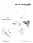
1
Tele-Medicine Cart
MANUAL 07. 11. 14
IM010-01
The Enovate Medical Computer Cart was designed to set a new standard in quality. Enovate
Medical’s goal is to provide a cart that is built right, ready for years of use, and backed by a
commitment of exemplary service and support.
Thank you for purchasing the
Enovate Medical telemedicine cart
Distributed by:
Enovate Medical
US Headquarters
1152 Park Avenue
Murfreesboro, TN 37129
Suppor [email protected]
Toll free 888.909.8930
Miller Technical Services
7444 Haggerty RD.
Canton, Mi 48187
www.mtsmedicalmfg.com
Toll Free 888.489.6398
1
TABLE OF CONTENTS • MANUAL
2
1
WELCOME
4
WARNINGS
8
HARDWARE
10
TECHNICAL DATA
11
CART FEATURES
12
UNPACKING
14
INTERGRATION
15
INITIAL SETUP
16
MEDIA DEVICES
18
WIRE MANAGEMENT
21
e240 SETUP
22
POWER SYSTEM
28
KEYPAD OPERATION
38
STORAGE
39
FAQ
Congratulations on your purchase of the Enovate Medical tele-medicine
cart. Please do not use your tele-medicine cart until you have read this
manual in its entirety as it contains important safety and use information.
The Enovate Medical tele-medicine cart should only be used as outlined in
this manual. Be sure to keep the manual in a safe place for future reference. If at any time you have questions or concerns about the contents of
this manual or the use of your Enovate Medical tele-medicine cart, please
contact Enovate Medical Customer Service toll free at 888.909.8930
This manual and the accompanying product labels and safety labeling
materials of the Enovate Medical tele-medicine cart frequently employ
the use of symbols with or without accompanying text. Health products
regulatory agencies require the use of symbols, often in place of textual
statements, to enhance the legibility of labeling and thus improve the
conspicuousness of required information such as important safety
information. Your attention to the presence and content of symbols used in
this manual will help to ensure the safe use of your Enovate Medical telemedicine cart. The following chart depicts the symbols used and provides
a definition for each symbol found in this manual and in the labels and
labeling materials of the Enovate Medical tele-medicine cart.
Distributed by:
Enovate Medical
US Headquarters
1152 Park Avenue
Murfreesboro, TN 37129
[email protected]
Toll free 888.909.8930
Miller Technical Services
7444 Haggerty RD.
Canton, Mi 48187
www.mtsmedicalmfg.com
Toll Free 888.489.6398
3
IMPORTANT WARNINGS • MANUAL
The term “symbols” refers to the use of graphical symbols without equivalent accompanying text.
Symbols are used by medical device manufacturers to create uniform labels and labeling for
the United States, European Union, and any other countries that may permit their use in medical
products. By using symbols in place of some textual statements, manufacturers may enhance
the legibility of labeling and thus improve the conspicuousness of required information; especially
where information is contained upon product labels that are restricted in their space available.
The use of symbols on the product labels are intended to conform to international consensus
standards. The following chart depicts the symbols used and provides a definition for each
symbol found in the labels.
CAUTION, CONSULT ACCOMPANYING DOCUMENTS
CONSULT INSTRUCTIONS FOR USE
ELECTRIC SHOCK WARNING SYMBOL
MANUFACTURER
SN
REF
SERIAL NUMBER
CATALOG NUMBER
TYPE B APPLIED PART
EC REP
AUTHORIZED REPRESENTATIVE IN THE EUROPEAN COMMUNITY
The CE mark on this product indicates it has been tested to and conforms
with the provisions noted within the
93/42/EEC Medical Device Directive
Accredited testing laboratory has evaluated a sample of the product and
determined that it complies with applicable national standards, <enter , as
applicable, Canadian and US>.
4
IMPORTANT WARNINGS • MANUAL
Warnings
Important Warnings
Electrical Shock Warning
The above symbols represent safety warnings that require significant attention when
seen on the EMC cart or in the user manual. Failure to do so could result in minor
injury, major injury, or even death.
Do not use in the presence of a anesthetic mixture with air or with oxygen or
nitrous oxide.
SERVICE AND REPLACEMENT
Do not attempt to service or replace any part of the Enovate Medication Cart
unless directed to do so through Enovate Medical approved documentation
(i.e., this User Manual or other instructions). Only Enovate Medical or an
Enovate-certified entity may service or replace the cart components. If any
component on the cart is missing or damaged, the cart must not be used.
Contact Enovate Medical immediately to request service.
Maintenance
During preventive maintenance cart should be turned off
SAFE WORKING LOADS
Safe working loads labels must be abided by for all parts of EMC
MAXIMUM WEIGHTS
• Standard Monitor 16lbs.
• Dual Monitors 8lbs. on each VESA
• Fixed monitor 16lbs.
• Laptop tray 7lbs.
• Keyboard tray 1lbs.
• Drawer(s) 5lbs.
GROUNDING
Connect the Enovate Medication Cart to an equivalent receptacle marked
“Hospital Only” or “Hospital Grade” to ensure ground.
DANGEROUS VOLTAGE
Do not remove battery drawer—there may be live parts inside, even when
the Enovate Medication Cart is turned off.
DO NOT OPEN THE BATTERY AND POWER SYSTEM COMPARTMENT
Unauthorized personnel opening the power system compartment may cause
injury and/or death. If the unit is not working properly, please contact Enovate.
DO NOT USE THE UNIT IN OR NEAR WATER OR OTHER LIQUIDS
If the unit becomes wet, unplug it immediately, wipe away any excess liquid
and allow it to dry before use.
5
IMPORTANT WARNINGS • MANUAL
DO NOT OPEN MORE THEN ONE DRAWER AT A TIME
Cart worksurface and monitor must be in lowered position and all drawers
must be closed during transport.
DO NOT TRANSPORT THE CART UP OR DOWN STAIRS
Multiple Portable socket-Outlets (MPSO) shall not be placed on the floor.
Additional MPSO or extension cord shall not be connected to the system.
MPSO provided with the system shall only be used for powering equipment
which forms part of the system.
DO NOT connect non-medical equipment, which has been supplied as part of
the system, directly to a wall outlet.
DO NOT connect electrical equipment which, has not been supplied as a part
of the system, to the MPSO
The leakage current could increase when connected to other equipment.
The operator should take precautions to avoid touching the rear panel input
and output circuitry and the patient at the same time.
To isolate the system from the mains supply remove the mains plug from the
wall socket.
NOTE: The power outlet provided in the system is powered from an isolation
transformer. The maximum output rating of this outlet is 300 Watts.
The medical system device as supplied by Enovate Medical is suitable for use
within a patient environment.
CAUTION: Non-medical equipment which may have been supplied as part
of the system should only be connected to the cart MPSO which is powered
from an isolation transformer. Connection of non-medical equipment to
other outlets may lead to an increase of leakage current.
6
IMPORTANT WARNINGS • MANUAL
STATEMENT OF USE:
The Enovate Medical Computer Cart was designed to set a new standard in quality,
ease of use, and customer satisfaction. Our goal is to provide a product that is built to
exacting standards and is ready for years of durable service. This product is designed
to be safely used within general patient areas and is meant to aid in the entering or
retrieving of clinical data, and it complies with UL 60601-1 electromagnetic leakage and
safety requirements if used in accordance with the boundaries and suggestions of this
manual.
THIS PRODUCT IS CLASSIFIED AS:
• Class I internally powered UPS type B
• This product is designed for continuous operation
• IPXO for water ingress
TESTED TO COMPLY WITH:
• UL60601-1: Issued: 2003/04/25 Ed:1 Rev: 2006/04/26 UL Standard for Safety
Medical Equipment, Part 1: General Requirements for Safety
RECOMMENDED SHIPPING AND OPERATIONG CONDITIONS:
• Temperature Range
25°F- 120°F
• Humidity Range
10% - 80%
TERMS OF USE:
Removing or damaging the serial number and barcode label will void
all cart warranties.
For laptop compatibility please check with your local Enovate Medical Representative or call us
toll-free (877) 890-6131.
Unauthorized personnel opening the battery may cause injury and/or death.
If the unit is not working properly, please contact Enovate Medical Customer Service toll free at
877.258.8030
Contact Us
Customer Service
Enovate Medical
US Headquarters
1152 Park Avenue
Murfreesboro, TN 37129
[email protected]
Toll free 888.909.8930
7
IMPORTANT WARNINGS • MANUAL
Hardware Included
1x
Camera Mount
4x
M4 x 0.7 x 16
Pan Head Screw
4x
Dual Lock Pads
8
4x
M4 x 0.7 x20
Pan Cross Head Screw
1x
1/4 - 20 x .25”
Button Head Screw
8x
Cable Tie
& Adhesive Pad
4x
Cable Tie
Warranty • MANUAL
Tools Needed
5/32
Allen Wrench
Adjustable
Wrench
Adjustable
Wrench
99
Cart Features • MANUAL
Technical Data
60601 COMPLIANT POWER SYSTEMS
350 AC POWER SYSTEM
105 - 120 VAC, 50-60Hz Input 300w maximum output
105 - 120 VAC, 60Hz combined 300w maximum output
The powered EMC includes a 6-input 5-15 NEMA AC power cord set (MPSO).
150 AC POWER SYSTEM
105 - 120 VAC, 50-60Hz Input
105 - 120 VAC, 60Hz combined 150w maximum output
The powered EMC includes a 6-input 5-15 NEMA AC power cord set (MSPO).
BATTERIES
40 Amp hour Sealed Lead Acid (SLA)
40 Amp hour Lithium Iron Phosphate
Lead Battery Must be Recycled
tooltip
13” D x 16.5” W x 3”H
Interior Usable Space
LAPTOP DIMENSIONS
the large EMC (Enovate Medical Cart) tray has 13"D x 16.5"W x 3"H
interior usable dimensions for laptop or CPU storage.
FLAT PANEL DISPLAY DIMENSIONS
The EMC accommodates most 15" to 21" Flat Panel Displays
10
Cart Features
HD Camera
eLift
Codec Storage
12” Height
Adjustment
8” Pull-Out Adjustment
11
Technical Data • MANUAL
Unpacking
Promptly unpack your products to check for completeness and damage caused by shipping.
Immediately after receiving your carts, ALL batteries must be fully charged to ensure the
duration of their warranty.
1
3
12
2
Before removing the EMC
from a shipping container
check over the packaging
and pallet to prevent
accepting an item with
shipping damage.
Remove cardboard lid and
cardboard spacers.
Use scissors or a utility
knife to cut and remove
the two outer straps.
Unpacking • MANUAL
4
5
Remove cardboard walls
and plastic bag. NOTE:
This step requires two
people. Lift cart (with
foam castor braces still
attached) out of the cardboard base.
6
Remove foam
castor braces.
Open tray and check for
integration kit and locate all
optional accessories.
13
Safety • MANUAL
Integration
INTEGRATION KIT
Rubber bumpers for keyboard retention
18” USB A to USB B Cable
8” zip ties
Pair of keys
Cable management cover (for LCD units only)
Powered Control Board (See Below)
FRONT
BACK
Powered Control Board and USB Hub – Each powered cart includes a 3 input USB
adapter. In laptop versions this USB hub also functions as risers to adjust the height of
the screen.
14
Inital Setup • MANUAL
Initial Setup
STEP 1
Align screws with the quick mount
slots in the monitor pole VESA
plate. Slide the monitor into place
and tighten the screws.
STEP 2
Insert the second set of the M4 x 0.7x20
pan cross head screws into the bottom
two holes of the monitor pole VESA
plate to properly secure the monitor.
15
Initial Setup • MANUAL
Media Devices
NOTE:
Before beginning installation
ensure that the cart's power is off.
STEP 1 Mount the camera to the camera
mount with the ¼ -20 x .25” Button
Head Screw.
STEP 2 Locate the Codec Unit Camera Cable
(large 3 wire cord) and plug the power into
the far left port on camera, the camera
control cord into the ‘IN’ port and the DVI
cable into the camera out port.
Power Camera Control "IN" DVI Camera "OUT" Codec Unit Camera Cable
16
Media Devices • MANUAL
STEP 3
Locate the microphone pod
and mic cord. Plug the mic
cord into the ‘OUT’ port.
STEP 4
Using two tabs of Duel Lock Velcro
attach the microphone pod under the
camera as shown.
STEP 5
Locate the power and HDMI cables for the monitor and plug in each cable into
their respective slots.
Power HDMI 17
Wire Management • MANUAL
Wire Management
STEP 1
Bundle camera wires and mic wires
together. Using mounts and tie wraps
secure neatly down the center of the plate.
STEP 2
Loop power and HDMI cables from the
monitor up to camera wires and secure
together with tie wrap.
STEP 3
Attach wire management cover to
monitor post
Mount and tie wrap
Tie wrap
18
Wire Management • MANUAL
STEP 1
Using Duel Lock velcro mount the
Codec to the lower left corner with
ports facing right.
STEP 2
Insert CAT5 cord into top LAN port on
codec and run cable out the top right
rear hole of box and hang on post.
(see page 8)
STEP 3
Using Duel Lock mount the power
brick in lower right and plug into
Codec. Run power plug in rear hole
of cart to power strip under the
work surface. (see page 8)
19
Wire Management • MANUAL
STEP 4
Plug additional devices into Codec
(see below). Use zip tie mounts for
wire management.
Codec Unit
Camera
3-ways Microphone POD
Microphone cable
Codec unit camera cable
HDMI cable
Ethernet cable for LAN, 4m
Power supply and power cable
2
5
7
8
1
4
6
3
20
1
2
3
4
5
6
7
8
e240 Setup • MANUAL
e240 Setup
CONNECTING WITH A PC
POWER S/W
POWER
DVI IN
RGB IN
SERVICE
AUDIO IN
Computer/
Ordinateur
DVI IN
AUDIO
RGB IN
CONNECTING TO THE VIDEO CONFERENCE MONITOR
MIC
POWER S/W
POWER
LAN
LAN
Computer/
Ordinateur
Hub/
Concentrateur
•
Connect headphones and or MIC when needed. This product had internal
speakers and MIC
•
Ensure that only one of the two {LAN} ports are connected to the network
21
Power System • MANUAL
Power System
INITIAL POWER-UP
Before the initial power up and use the EMC cart must be charged for 24 continuous
hours to insure maximum battery life. Equipment may be connected during this time.
EMC FUEL GAUGE
Low Battery Alarm Mute
Computer Reboot
Cart Power ON/OFF
Cart On/Off Indicator
Charge Indicator
Work Light ON/OFF
Battery Fuel Gauge
*Important* Do not use sharp objects such as pens or pencils to depress/
actuate the cart’s buttons.
• Cart Power Button – press and hold for 2-3 seconds to turn cart power ON or OFF.
The Cart On/Off indicator LED will light green, when cart power is ON.
On a cold startup (all LEDs dark), all four battery charge LEDs will light green for
about 10 seconds.
When startup is complete, the Cart On/Off indicator LED will remain Green, and
the battery charge indicators will reflect the battery charge level. (See above
image)
• Low Battery Alarm Mute Button A beeper will sound on low battery or severe
(red) fault alarms. The mute button silences the beeper. (Note, the power system
can also be configured for silent operation, through MPM Techview software)
• Battery Fuel Gauge - The first LED displays power on/ power off. LEDs two
through five indicate charge level. All four LEDs green -- battery is full. One LED
flashing Green means battery is charging. When LED 2 flashes yellow or red,
battery charge is low, cart should be connected to AC power. (NOTE: If LEDs 2 &
3 flash yellow or red at the same time, there is a fault in the power system. If both
flash Yellow -- service soon. If both flash Red -- service now; turn off computer,
turn cart power off.)
• Work Light Button - On/Off toggle for LED work light. If left on, the light will
auto-shutoff after five minutes.
• Computer Reboot Button (OPTIONAL) Can function as a remote reboot button or
a power toggle button. Extra hardware, found in OPTIONAL ACCESSORIES, and
compatible hardware are required for function.
22
Battery Charge LED Meter Display
Low
Approximate
Battery Module
CHARGE
LEVEL INDICATORS (DISCHARGING, CART UNPLUGGED FROM ACBattery
POWER)
Alarm*
Charge Level
90%-100%
Green
Green
Green
Green
OFF
60%-89%
Green
Green
Green
OFF
OFF
Battery Charge LED Meter Display
31%-59%
Yellow
Yellow
OFF
OFF
ON
Low
Approximate
<=30%
Flashing Red
OFF
OFF
OFF
ON
Battery
Battery Module
battery alarm will beep once per second unless it is silenced by pressing the “Alarm Mute” button. Once the charge level falls
* The lowLevel
Alarm*
Charge
below 30% (and shutdown is imminent) the alarm will resume again after one minute. The user should save open files and safely
90%-100%
Green
Green
Green Software isGreen
shutdown connected equipment
immediately. If the cart
is unattended and PowerAlert
loaded on a computerOFF
connected
to the Power Supply Module,Green
PowerAlert will automatically
save open files prior
to automatic shutdown.
60%-89%
Green
Green
OFF
OFF
31%-59%
Yellow
Yellow
OFF
OFF
ON
<=30%
Flashing Red
OFF
OFF
OFF
ON
* The low battery alarm will beep once per second unless it is silenced by pressing the “Alarm Mute” button. Once the charge level falls
below 30% (and shutdown is imminent) the alarm will resume again after one minute. The user should save open files and safely
shutdown connected equipment immediately. If the cart is unattended and PowerAlert Software is loaded on a computer connected
to the Power Supply Module, PowerAlert will automatically save open files prior to automatic shutdown.
CHARGE LEVEL INDICATORS (CHARGING, CART PLUGGED INTO AC POWER)
Battery Charge LED Meter Display
Approximate
Battery Module
Charge Level
Green
Green
Green
90%-100%
Green
Flashing Green
Green
Green
60%-89%
Green
Battery Charge LED Meter Display
Flashing Green
OFF
Green
31%-59%
Green
Approximate
Flashing Green
OFF
OFF
<=30%
Green
Battery Module
recommends that the power supply be plugged into a wall outlet, charging the battery as often as possible. Charging the
* Tripp Lite
Charge
Level
battery for brief intervals DOES NOT adversely affect battery performance. However, leaving the battery fully discharged for long
Green
Green
Green
90%-100%
Green
periods of time DOES adversely
affect battery performance.
Flashing Green
Green
Green
60%-89%
Green
Flashing Green
OFF
Green
31%-59%
Green
Flashing Green
OFF
OFF
<=30%
Green
* Tripp Lite recommends that the power supply be plugged into a wall outlet, charging the battery as often as possible. Charging the
battery for brief intervals DOES NOT adversely affect battery performance. However, leaving the battery fully discharged for long
periods of time DOES adversely affect battery performance.
Recharging status can be viewed on LED readout described above. The last (5th) LED will
stop flashing when charge is complete.
While charging, the components of the cart may be used. The Power Supply of the EMC
will simultaneously charge the batteries and run the connected components.
Recharge Time Required
• SLA
3-4 hours depends on battery size
• Lithium
2.5 Hours
23
Power System • MANUAL
FUSES
Two external fuses protect the EMC’s power system from irregular or
potentially dangerous power surges. The fuses are in a dangerous area and
should be replaced by Enovate authorized personnel only.
FUSE SPECIFICATIONS:
• 10A Fast Acting Mini Fuse 5mm X 20mm
• 30A Fast Acting Fuse 10mm X 38mm
All power connections should be disconnected before any service
POWERALERT SOFTWARE
Visit www.tripplite.com for PowerAlert management software download and
full instructional manual.
SLA BATTERY CHARGE/DISCHARGE CYCLE
Cart is in the OFF/Standby mode.
When the power button is pressed, two LEDs will briefly illuminate, the 2nd LED red,
and 5th LED green), then all 4 LED fuel gauge LED will light green for about 10 seconds.
The first LED will illuminate green indicating the cart has been powered up; and the
fuel gauge LEDs will illuminate to reflect the present level of charge in the battery.
24
Power System • MANUAL
SLA BATTERY CHARGE/DISCHARGE CYCLE CONT.
Five illuminated green LEDs indicate battery output is ON and the battery us fully
charged.
Four illuminated green LEDs indicate battery cart power is ON , the battery discharging and has between 50% and 75% charge remaining.
Three illuminated green LEDs indicate battery cart power is on, battery is discharging
with between 25%-50% of the battery charge remaining.
Green power LED and a flashing amber LED indicates low battery warning; a low battery warning alarm will sound to indicate the battery needs to be charged.
The amber LED will change to flashing red and the alarm will sound twice as fast when
the battery has reached critical low power (less than 5% charge remaining). The alarm
will sound every second until the battery fails to power the cart or the cart is plugged
into AC wall power.
Indicates Flashing
25
Power System • MANUAL
SLA BATTERY CHARGE/DISCHARGE CYCLE CONT.
Battery is completely discharged. Cart will not power on or a combination of LEDs will
momentarily illuminate when power button is pressed.
Once plugged into AC wall power, the position of the flashing LED indicates the level of
recharge in process. If battery was fully discharged, the 2nd LED will flash red until at
least 6% of the battery charge has been recovered. The first LED will be illuminated
only when the cart is powered on.
Additional LEDs illuminate as the level of battery charge increases.
Three illuminated green LEDs indicate battery is more than 75% charged, but still
charging the top 25%.
Four illuminated green LEDs indicate battery is 100% charged.
Indicates Flashing
26
Power System • MANUAL
COMMON PHOSPHATE BATTERY TROUBLE ISSUES
If the cart is plugged in to charge, and LED 2 & 3 continually flash red together, this
indicates that the battery voltage is lower than the charging system will recognize.
This may require a some time for the power system to recover the battery on its
own. If the battery has been on a in recovery mode for too long, and the cart still will
not charge, the battery needs to be replaced.
Two amber LEDs on and then off without the cart powering up can be an indication
of a few different conditions. A communication error between the battery and the
charging system possibly due to a wrong battery firmware matchup. It can also
mean the RJ45 connection between the battery and charging system is bad. Note:
if it is found that the connection between the SL Phosphate battery and the Power
system is bad and has been restored; the yellow Anderson connection between
the battery and the power system must be disconnected for 10 seconds to allow
the charging system to reset! If you don’t, the same problem may continue even
after the RJ45 connection has been restored. This could also indicate the battery
is too low to power up the cart. If you plug the cart into the wall to charge and no
lights show up on the key pad to indicate charging and the cart won’t power up, the
problem is most likely the connection between the battery and the TRIPP•LITE, or
wrong firmware for the battery in use.
Indicates Flashing
27
Keypad Operation • MANUAL
Keypad Operation
LED INDICATOR
KEYPAD LOCK
For demo purposes
the combination to
unlock all drawers:
5-4-3-2-1
TYPE A
KEYPAD - TYPE A
There are five keys that are used to enter 5-digit PIN codes.
LED
A single multi-color LED on the keypad provides feedback to the user as key sequences
are pressed. The LED can appear as green or red.
LED COLOR
FLASH ONCE
FLASH TWICE
Green
Each key press
Sucessful operation
Red
N/A
Failed operation or timeout
MASTER CODE
There is one, 5-digit Master PIN Code for use by the system administrator. The Master
Code is used to assign User PIN Codes and for other maintenance functions.
The factory default Master Code is 12345.
USER PIN CODES
Up to 100, 5-digit PIN Codes can be assigned for use by hospital personnel to access
the drawers. When a user enters their valid PIN code, the drawer unlocks to allow
access. The drawer relocks after a configurable time interval.
The factory default User PIN Code is 54321.
28
Keypad Operation • MANUAL
RESERVED PIN CODES
The following PIN codes are reserved for administrative usage. These codes cannot be
assigned as either the Master Code or as a User PIN Code.
PIN
Code Description
13344
Add a user PIN code.
13341
Delete a user PIN code.
13342
Delete all user PIN codes and restore default user PIN code 11111.
13321
Turn on USB. Keypad behaves like a keyboard for the PC.
13322
Turn off USB.
13333
Report configuration over USB (to a text editor).
13343
Set the drawer unlock time.
13351
Enter the bootloader to upgrade the embedded firmware.
13331
Reserved for future use.
13332
Reserved for future use.
13352
Reserved for future use.
13354
Reserved for future use.
13343
Reserved for future use.
FACTORY DEFAULTS SUMMARY
All units are shipped from the factory with the following default values:
Item
Default Value
Master Code
12345
User PIN Code
54321
Unlock Time
15 seconds
USB Interface
Off
29
Keypad Operation • MANUAL
LED INDICATOR
KEYPAD LOCK
For demo purposes
the combination to
unlock all drawers:
9-7-5-3-1
TYPE B
KEYPAD - TYPE B
There are five keys that are used to enter 5-digit PIN codes. All PIN codes are stored,
processed and reported as odd numbers
LED
A single multi-color LED on the keypad provides feedback to the user as key sequences
are pressed. The LED can appear as green or red.
LED COLOR
FLASH ONCE
FLASH TWICE
Green
Each key press
Sucessful operation
Red
N/A
Failed operation or timeout
MASTER CODE
There is one, 5-digit Master PIN Code for use by the system administrator. The Master
Code is used to assign User PIN Codes and for other maintenance functions.
The factory default Master Code is 13579.
USER PIN CODES
Up to 100, 5-digit PIN Codes can be assigned for use by hospital personnel to access
the drawers. When a user enters their valid PIN code, the drawer unlocks to allow
access. The drawer relocks after a configurable time interval.
The factory default User PIN Code is 97531.
30
Keypad Operation • MANUAL
RESERVED PIN CODES
The following PIN codes are reserved for administrative usage. These codes cannot be
assigned as either the Master Code or as a User PIN Code.
PIN
Code Description
15577
Add a user PIN code.
15571
Delete a user PIN code.
15573
Delete all user PIN codes and restore default user PIN code 11111.
15531
Turn on USB. Keypad behaves like a keyboard for the PC.
15533
Turn off USB.
15555
Report configuration over USB (to a text editor).
15575
Set the drawer unlock time.
15591
Enter the bootloader to upgrade the embedded firmware.
15551
Reserved for future use.
15553
Reserved for future use.
15593
Reserved for future use.
15597
Reserved for future use.
15575
Reserved for future use.
FACTORY DEFAULTS SUMMARY
All units are shipped from the factory with the following default values:
Item
Default Value
Master Code
13579
User PIN Code
97531
Unlock Time
15 seconds
USB Interface
Off
31
Adminisitrative Functions • MANUAL
Administrative Functions
All code entries require five key presses. Too few or too many key presses will result in
a failed operation.
NOTE: In all of the following examples it is advised to have all key strokes written down
for the desired operation. If there is a pause of 2 seconds or longer between any two
keys the red LED will flash twice to indicate a failure. To cantcel an operation, stop
pressing keys and let the operation fail due to a timeout. When an operation completes
successfully there will be two green flashes.
CHANGING THE MASTER CODE
1. Enter the current Master Code.
2. Enter the current Master Code again.
3. Enter the new Master Code.
4. Pause for 2 seconds.
5. T he green LED flashes twice for success. The new Master Code
has been saved and activated.
IMPORTANT: RECORD YOUR MASTER CODE AND SAVE IT IN A SAFE PLACE.
ADDING A USER PIN CODE
1. Enter the Master Code.
2. Enter 13344 (TYPE A) or 15577 (TYPE B).
3. Enter the PIN Code to add.
4. Pause for 2 seconds.
5. T he green LED flashes twice for success. The PIN Code has been saved and
activated.
DELETING A USER PIN CODE
1. Enter the Master Code.
2. Enter 13341 (TYPE A) or 15571 (TYPE B) .
3. Enter the PIN Code to delete.
4. Pause for 2 seconds.
5. The green LED flashes twice for success. The PIN Code has been deleted.
DELETING ALL USER PIN CODES AND RESTORING THE DEFAULT PIN CODE
1. Enter the Master Code.
2. Enter 13341 (TYPE A) or 15573 (TYPE B).
3. Pause for 2 seconds.
4. T he green LED flashes twice for success. All User PIN Codes have
been deleted and the factory default PIN code 11111 restored.
32
Administrative Functions • MANUAL
SETTING THE DRAWER UNLOCK TIME
1. Enter the Master Code.
2. Enter 13343 (TYPE A) or 15575 (TYPE B).
3. Enter the 5-digit time code for the required unlock time
4. Pause for 2 seconds.
5. T he green LED flashes twice for success. The new Unlock Time has been saved
and activated.
UNLOCK TIME CODES - TYPE A
Unlock Time
(in seconds)
Time Code
Unlock Time
(in seconds)
Time Code
5
11111
18
11134
10
11112
19
11135
15
11113
20
11141
20
11114
21
11142
25
11115
22
11143
30
11121
23
11144
35
11122
24
11145
40
11123
25
11151
45
11124
26
11152
50
11125
27
11153
55
11131
28
11154
60
11132
29
11155
65
11133
30
11211
UNLOCK TIME CODES - TYPE B
Unlock Time
(in seconds)
Time Code
Unlock Time
(in seconds)
Time Code
5
11111
18
11157
6
11113
19
11159
7
11115
20
11171
8
11117
21
11173
9
11119
22
11175
10
11131
23
11177
11
11133
24
11179
12
11135
25
11191
13
11137
26
11193
14
11139
27
11195
15
11151
28
11197
16
11153
29
11199
17
11155
30
11311
33
User Functions • MANUAL
User Functions
UNLOCKING THE DRAWERS
1. Enter a valid User PIN Code
2. Pause 2 seconds
3. The green LED flashes twice for success and the drawers unlock.
4. A fter 15 seconds (default) or the user programmed unlock time, the drawers will
be relocked.
ODD NUMBERS - TYPE B ONLY
Since all key strokes are recorded and processed as odd numbers it is important to
know that duplicate numbers do exist and can cause faults.
Example – The number 24680 is the same as 13579.
If the administrator was to add the pin code 24780 to the system you will notice that it will
be reported back in the “Current Configuration Report” as 13579. If you look closely at the
keypad you will notice that the above two numbers are the same keystrokes according to
the system.
It is perfectly OK for the user of the system to remember a number they are familiar
with like 24680 but the administrator that tries to enter that pin may result in a fault if
13579 is already in use.
To avoid confusion, the administrator must require all users to use pin numbers that
consist of odd numbers. This way the numbers selected and the numbers that are
reported back in the report will always match.
34
Overide • MANUAL
Emergency Key Switch Overide
In the event of a cart power failure or non-functioning keypad, an emergency lock
override has been provided. The key switch override is located on the underside of the
drawer system between the webbing of the cart shelf.
UNLOCKING THE DRAWERS WITH EMERGENCY KEY SWITCH OVERRIDE
1. Turn key clockwise and release to deactivate locks. Note: Key switch is
momentary and should not be held in the unlocked position
2. All locks will remain open for 30 seconds
3. Once the locks have retracted, the keyswitch can be used again, the emergency
override will activate the locks a maximum of 5 times.
35
Overide • MANUAL
INDICATOR LEDS
Red and Green indicator LEDs are located on the underside of the drawer system,
next to the keyswitch.
LED Color
LED STATUS
GREEN
ON
Indicates that the AUX battery is
being charged or is fully charged
and is above the voltage level of
12.79V
GREEN/RED
OFF
Indicates that the voltage is
below 12.79V. Battery voltage is
in the usuable range and will still
activate the locks when the key
switch is used.
RED
OFF
Indicates normal operation
ON
Indicates a fault and the auxilary
battery has dropped below 10.59
volts. If the RED LED turns on
after the key switch is used it will
immediately turn off the locks. If
the RED LED is already on before
using the key switch, the key
switch will not work.
RED
36
Storage • MANUAL
STORAGE
CAUTION! Even after the Power Supply Module is unplugged, its outlets
may still deliver current, until it is disconnected from the Battery Module
and completely turned OFF (deactivated). Before storing your Power Supply
Module, make sure the Battery Module is fully charged. Next, turn the Power
Supply Module completely OFF by following these steps:
• Unplug the Power Supply Module from the wall outlet (all LEDs and outlets should
be OFF);
• Disconnect the battery module from the system. If the cart has a medication
cabinet, disconnect the battery in the medication cabinet as well.Press and hold
the “Power” button for at least one second to dissipate any hazardous electrical
charges that might remain inside the Power Supply Module (the Power Supply
Module will click and the alarm may beep briefly).
• If you store the Power Supply Module and Battery Module for an extended period
of time, recharge the Battery Module once per month. If the cart has a medication
cabinet, the cart must be left on while charging, and must be charged for at least
12 hours. This ensures the backup battery gets a full charge.
• Follow the connection and recharge procedure in the “Connection / Start-Up”
section. If you leave the Battery Module discharged for an extended period of
time, it will suffer a permanent loss of capacity.
No AC output power
available at outlets.
Turn Unit On: Turn the Power Supply Module ON using the “Power” button.
Check Connections: Check to make sure the Power Supply Module and Battery
Module are properly connected. Also, make sure the RUI is connected to the
Power Supply Module. The Power Supply Module will not supply AC power
without these connections. The user may need to turn on the Power Supply
Module manually (using the RUI’s “Power” button) after reconnection.
Recharge Batter y Module: if the Batter y Module is fully discharged, the
Power Supply Module will be unable to supply output power through its
AC Outlets. Allow the batter y fully charge.
Battery Module not
recharging even with AC
utility power present.
Check Connection: Check to make sure the Power Supply Module and
Battery Module are properly connected. Also, make sure the Power Supply
Module’s power cord is plugged into a live AC wall outlet.
Replace Battery Module: The Battery Module will reliably supply backup power
for several years with the Lithium Ion and several months for the SLA. When
the battery module reaches then of its service life it will supply progressively
diminishing capacity. Contact Enovate for additional information.
Low battery alarm sounding.
Check Battery Charge Level LED Meter: Silence the alarm, if desired, with
the “Alarm Mute” button. Check LED meter to determine the percentage
of charge remaining. When the charge level falls below 10%, the Battery
Module is nearly depleted and Power Supply Module shutdown is imminent.
The user should save open files and safely shutdown connected equipment
immediately. If the cart is unattended and PowerAlert Software is loaded
on a computer connected to the Power Supply Module, PowerAlert will
automatically save open files prior to automatic shutdown.
37
FREQUENTLY ASKED QUESTIONS
What is the LED Fuel Gauge
The LED Fuel Gauge has 5 LEDs: One On/Off LED on the far left and four battery level
LEDs, position 1 – 4 from left to right and indicating low to high from left to right.
What is the status of the unit when the unit is plugged in, AC LED is on and 4 Battery
lights (solid green) are on?
With the LEDs in this configuration and the unit plugged in, it is indicated that the unit
is on and that the battery is fully charged (98 – 100%). The unit will pass power to the
connected equipment using utility power. Your unit is functioning properly.
What is the status of the unit when it is plugged in, AC LED is off and 4 Battery lights
(solid green) are on?
With the LEDs in this configuration and the unit unplugged it is indicated that the unit is
off and that the battery is fully charged (98 – 100%). The unit will not pass power to the
connected equipment using battery power. Your unit is functioning properly.
What is the status of the unit when it is plugged in, AC LED is on, 3 Battery lights (solid
green – position 1, 2 and 3) are on and the 4th position Battery light flashing?
With the LEDs in this configuration and the unit plugged in, it is indicated that the unit
is on and that the battery is 75% – 98% charged. The unit is currently charging and will
pass power to the connected equipment using utility power. Your unit is functioning
properly.
What is the status of the unit when the unit is plugged in, AC LED is off, 3 Battery lights
(solid green – position 1, 2 and 3) are on and the 4th position Battery light flashing?
With the LEDs in this configuration and the unit unplugged it, is indicated that the
unit is off and that the battery is 75% – 98% charged. The unit will not pass power to
the connected equipment using battery power. Your unit is functioning properly.
What is the status of the unit when the unit is plugged in, the AC LED is off, 2 Battery
lights (solid green – position 1 and 2) are on and the 3rd position Battery light flashing?
With the LEDs in this configuration and the unit unplugged indicates that the unit is off
and that the battery is 50% – 75% charged. The unit will not pass power to the connected equipment using battery power. Your unit is functioning properly.
What is the status of the unit when the unit is plugged in, the AC LED off, 1 Battery
light (solid green – position 1) is on and the 2nd position Battery light is flashing?
With the LEDs in this configuration the unit is charging but will not pass power to the
connected equipment using battery power. To pass power to the connected equipment
the unit must be turned on (Online mode). Your unit is functioning properly.
38
39
WE ADVISE THE USER TO CARRY OUT ALL CLEANING, ADJUSTMENT, STERILIZATION AND
DISINFECTION PROCEDURE SPECIFIED HEREIN
GENERAL CLEANING INSTRUCTIONS
• Use non abrasive cleaners or mild cleaning solutions. Do not use abrasive cleaners, solvents, polishes, waxes or steam cleaning tools.
• As a precaution to test the suitability of a cleaning product, apply to an inconspicuous area,
minimizing the time of exposure and the amount of cleaning agent (diluting as recommended by the supplier) in order to prevent any damage to the surface.
• Contamination by intensively colored substances, for example coffee, iodine, or dyes,have to be
removed immediately.
• Power System should be inspected bi-annually to ensure vent holes and pan guard are free of dust and
debris.
SPECIFIC CLEANING INSTRUCTIONS
• Microphone (if present) use electronic equipment cleaner
• Camera (if present) use electronic equipment cleaner
• Monitor (if present) use electronic equipment cleaner
40
41
42
Enovate Medical Tele-medicine Carts are distributed by:
Enovate Medical, LLC
1152 Park Avenue
Murfreesboro, TN 37129
p. (888)909-8930 f. (6615)896-1652
www.enovatemedcial.com [email protected]
©2013 Enovate Medical LLC All Rights Reserved
Miller Technical Services
7444 Haggerty RD.
Canton, Mi 48187
www.mtsmedicalmfg.com
Toll Free 888.489.6398
43
44
45
1152 Park Avenue
Murfreesboro, TN 37129
p. (888)909-8930 f. (615)896-1652
www.enovatemedical.com
[email protected]
©2013 Enovate Medical LLC. All Rights Reserved