1
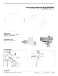
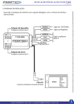
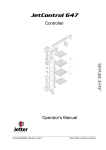
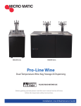
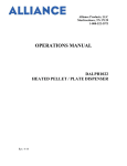
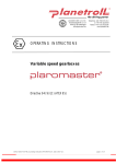
slimline
IM022-01
MANUAL 09. 15. 15
The Enovate Medical Slimline Cart was designed to set a new standard in quality. Enovate Medical’s
goal is to provide a cart that is built right, ready for years of use, and backed by a commitment of
exemplary service and support.
Thank you for purchasing the
Enovate Medical Slimline Cart
Distributed by:
Enovate Medical
US Headquarters
1152 Park Avenue
Murfreesboro, TN 37129
Suppor [email protected]
Toll free 888.909.8930
For laptop compatibility please check with your local
Enovate Medical Representative or call us toll-free (888) 909-8930
1
TABLE OF CONTENTS • MANUAL
IMPORTANT WARNINGS • MANUAL
Congratulations on your purchase of the Enovate Medical cart. Please do
not use your medical cart until you have read this manual in its entirety as
it contains important safety and use information. The Enovate Medical cart
should only be used as outlined in this manual. Be sure to keep the manual
in a safe place for future reference. If at any time you have questions or
concerns about the contents of this manual or the use of your Enovate
Medical cart, please contact Enovate Medical Customer Service toll free at
888.909.8930
2
1
WELCOME
3
WARNINGS
8
EMI
9
OVERVIEW
10
UNPACKING
12
CART FEATURES
14
POWER SYSTEM
18
POWER SPECIFICATIONS
20
SYSTEM ELECTROMAGNETIC EMISSONS
This manual and the accompanying product labels and safety labeling
materials of the Enovate Medical cart frequently employ the use of symbols
with or without accompanying text. Health products regulatory agencies
require the use of symbols, often in place of textual statements, to enhance
the legibility of labeling and thus improve the conspicuousness of required
information such as important safety information. Your attention to the
presence and content of symbols used in this manual will help to ensure
the safe use of your Enovate Medical cart. The following chart depicts the
symbols used and provides a definition for each symbol found in this manual
and in the labels and labeling materials of the Enovate Medical cart.
Distributed by:
Enovate Medical
US Headquarters
1152 Park Avenue
Murfreesboro, TN 37129
[email protected]
Toll free 888.909.8930
3
IMPORTANT WARNINGS • MANUAL
The term “symbols” refers to the use of graphical symbols without equivalent accompanying text.
Symbols are used by medical device manufacturers to create uniform labels and labeling for
the United States, European Union, and any other countries that may permit their use in medical
products. By using symbols in place of some textual statements, manufacturers may enhance
the legibility of labeling and thus improve the conspicuousness of required information; especially
where information is contained upon product labels that are restricted in their space available.
The use of symbols on the product labels are intended to conform to international consensus
standards. The following chart depicts the symbols used and provides a definition for each
symbol found in the labels.
CAUTION, CONSULT ACCOMPANYING DOCUMENTS
CONSULT INSTRUCTIONS FOR USE
ELECTRIC SHOCK WARNING SYMBOL
MANUFACTURER
SN
REF
Electrical Shock Warning
The above symbols represent safety warnings that require significant attention when
seen on the EMC cart or in the user manual. Failure to do so could result in minor
injury, major injury, or even death.
Do not use in the presence of a anesthetic mixture with air or with oxygen or
nitrous oxide.
USE A NONFLAMMABLE CLEANER WHEN CLEANING THE UNIT! Failure to
do so can result in death, explosion, and/or fire.
DO NOT LEAVE THE UNIT UNATTENDED AROUND CHILDREN! Failure to do
so can result in injury, and/or death.
CAUTION: THE POWER SYSTEM IS HEAVY. You must use proper lifting
techniques. Failure to do so can result in injury.
AVOID USING AN EXTENSION CORD WITH THE UNIT! If an operational error
occurs, the plug should be immediately removed from the socket.
CATALOG NUMBER
THE MAINS SOCKET SHOULD BE EASILY ACCESSIBLE! If an extension cord
must be used, ensure it is rated for the power capacity of the unit.
AUTHORIZED REPRESENTATIVE IN THE EUROPEAN COMMUNITY
The CE mark on this product indicates it has been tested to and conforms
with the provisions noted within the
93/42/EEC Medical Device Directive
Accredited testing laboratory has evaluated a sample of the product and
determined that it complies with applicable national standards, <enter , as
applicable, Canadian and US>.
4
Important Warnings
SERIAL NUMBER
TYPE B APPLIED PART
EC REP
Warnings
THIS CHARGER IS DESIGNED FOR USE WITH LITHIUM POLYMER BATTERIES!
For safety reasons, this charger must be used only for batteries which have
the right number of cells in series: Output divided by 4.1V or 4.2V.
DO NOT OPEN THE POWER SYSTEM! Unauthorized personnel opening the
power system may cause injury and/or death. If the unit is not working
properly, please contact Enovate Medical at 888-909-8930
DO NOT USE THE UNIT IN/NEAR WATER OR OTHER LIQUIDS! If the unit
becomes wet, unplug it immediately, wipe away any excess liquid and allow
it to dry before use. Failure to do so may cause electric shock, damage to the
unit, voiding of warranty, injury or death.
ALWAYS KEEP THE UNIT WELL VENTILATED! Do not block ventilation airways
or insert items into the ventilation slots. Failure to do so can cause the power
system to overheat and possibly cause fire, explosion, and/or death.
THE CHARGER CONTAINS DANGEROUS VOLTAGES AND THE COVER SHOULD
NOT BE REMOVED. All service or maintenance work should be carried out by
qualified service personnel by contacting Enovate Medical at 888-909-8930
5
IMPORTANT WARNINGS • MANUAL
SAFETY GUIDELINES:
MOBIUS POWER is designed to ensure both the highest level of product quality and
safety for the user. To maintain both quality and safety, follow the guidelines and
instructions in this manual.
• Use the MOBIUS POWER system only as intended.
• Do not place the power system near a window. Exposing the power system to rain,
water, moisture, or constant, direct sunlight can severely damage it.
• The MOBIUS POWER system has no user-serviceable, internal parts. To maintain
your warranty, refer all servicing to Enovate Medical qualified personnel.
• Do not cover or obstruct any venting holes on the MOBIUS POWER Main Power
Controller or the MOBIUS POWER Charging Stations.
• Store the MOBIUS POWER system within 10 to 30 degrees Celsius (50 to 86
degrees Fahrenheit). Storing the system outside the temperature range could
result in permanent damage.
• Use and maintain the cord set provided with the MOBIUS POWER Charging
Stations.
• If any cord or cable is frayed or damaged, replace it immediately with another of
the same type and rating as supplied by Enovate Medical.
• To clean the exterior of the power system/components, follow the UL 60601-1
standard for use in a hospital environment. See “Cleaning Procedures” for more
information.
• Before cleaning a MOBIUS POWER Charging Station, disconnect the enclosure
from its power source.
• CAUTION! Do NOT ship individual MOBIUS POWER Battery Packs by air.
Certain restrictions apply. Contact Enovate Medical for shipping instruction.
TRANSPORT/STORAGE
• Care should be taken to transport and store this system within a temperature
range of 32º F to 90º F (0º C to 32º C); Pressure 500 hPa to 1060 hPa; Humidity 20%
RH to 95% RH non-condensing.
IMPORTANT WARNINGS • MANUAL
IMPORTANT WARNINGS • MANUAL
STORAGE REQUIREMENTS:
• The Battery Pack must not be fully charged prior to storing.
CLASSIFICATIONS
• Charger: Class 1
• Main Controller: Class 1, Internally Powered
• Degree of Protection against Harmful Ingress of Water, IPX0
• EQUIPMENT not suitable for use in the presence of a FLAMMABLE
ANAESTHETIC MIXTURE WITH AIR or WITH OXYGEN OR NITROUS OXIDE.
ENVIRONMENTAL SPECIFICATIONS
• Operating Temperature: -25°C to 40°C
condensing
• Relative Humidity: 5 – 95% non-
WARRANTY
• Product Warranty: 1 year limited warranty on Battery Packs and 2 years on electronic components
• Extended Warranty: 1 year optional extension available on electronic
components
• Contact Stinger MedicalEnovate Medical directly for full warranty details
Approvals
ETL/CETL LISTING FOR NORTH AMERICA
• UL 60601-1 - UL Standard for Safety Medical Electrical Equipment, Part 1:
General Requirements for Safety First Edition
• CSA C22.2 NO 601.1-M90 - Issue:1990/01/11 (R2001) Medical Electrical
Equipment - Part 1: General Requirements for Safety General Instruction No
1; Supplement 1; 1994; Amendment 2 - February 1998 (R1997)
• Information Technology Equipment – Safety – Part 1: General Requirements,
UL60950-1, First Edition.
• CAN/CSA-C22.2 No. 60950-1-03, First Edition.
MEDICAL DEVICE DIRECTIVE 93/42/EEC - EUROPEAN UNION (EU) TESTING
AND REPORT SERVICES
• CENELEC EN 60601-1 - Medical Electrical Equipment Part 1: General
Requirements for Safety Incorporates Corrigendum July 1994;
Includes Amendments A1: 1993, A11: 1993, A12: 1993, A2: 1995 and A13: 1996;
IEC 601-1: 1988 + A1: 1991 + A2: 1995 + Corrigendum 1995, Modified
• IEC 60601-1-2 (2001-09) - Medical Electrical Equipment - Part 1-2: General
Requirements for Safety - Collateral Standard: Electromagnetic Compatibility
- Requirements and Tests Second Edition
CB SCHEME REPORT AND CERTIFICATE
• IEC 60601-1 - Medical Electrical Equipment Part 1: General Requirements
for Safety Second Edition
6
7
IMPORTANT WARNINGS • MANUAL
Cart Features • MANUAL
Overview
EMI (Electromagnetic Interference)
Portable and mobile RF communications equipment can affect Medical
Electrical Equipment. The use of accessories, transducers, and cables
other than those specified by the manufacturer, may result in increased
Emissions or decreased Immunity of the System. The System should not
be used adjacent to or stacked with other equipment and that if adjacent
or stacked use is necessary, the System should be observed to verify
normal operation in the configuration in which it will be used.
These limits are designed to provide reasonable protection against
harmful interference in a residential installation. This equipment
generates, uses, and can radiate radio frequency energy, and if not
installed and used in accordance with the instruction manual, may
cause interference to radio communications. However, there is no
guarantee that interference will not occur in a particular installation.
If this equipment does cause harmful interference to radio, television
or Medical Electrical Equipment reception, which can be determined
by turning the equipment off and on, the user is encouraged to try to
correct the interference using one or more of the following measures:
reorient or relocate the receiving antenna; increase the separation
between the equipment and the receiver; connect the equipment into an
outlet on a circuit different from that which the receiver is connected;
consult the dealer or an experienced radio/television technician for help.
The user must use shielded cables and connectors with this product.
Any changes or modifications to this product not expressly approved
by the party responsible for compliance could void the user’s authority
to operate the equipment. Operation is subject to the following two
conditions: (1) This device may not cause harmful interference, and
(2) This device must accept any interference received, including
interference that may cause undesired operation. MOBIUS POWER
meets or exceeds FCC Class A limits for EMI.
1
6
7
Battery Holster
2 (Charger
Board Inside)
8
Power Controller
3 Main
9
(Main Control Board and DC Boards Inside)
LCD Message Center
4
5
AC Holster Power Adaptor *
2-Battery Charging Station *
4-Battery Charging Station *
Charging Indicator Light
Indicator Light Instructions on front of Charging Station
*OPTIONAL components or system upgrades
Mobius Power Battery Pack
5
4
8
3
1
2
6
7
FULLY CHARGED
Solid green light
CHARGING
Blinking green light
ERROR
Solid yellow light
TECHNICAL SUPPORT:
[email protected] | 1-888-909-8906 ext. 303
9
FULLY CHARGED
Solid green light
CHARGING
Blinking green light
ERROR
Solid yellow light
TECHNICAL SUPPORT:
[email protected] | 1-888-909-8906 ext. 303
8
9
Cart Features • MANUAL
Cart Features • MANUAL
Unpacking
?
10
?
11
Cart Features • MANUAL
Cart Features • MANUAL
Cart Features
+60o
-13o
46.5in
(1181mm)
HIGHEST
59.5in
(1511mm)
30.5in
(775mm)
LOWEST
17in
16.5in
(419mm)
19.38in
(492mm)
59.5in
46.5in
(1511mm)
(1181mm)
HIGHEST
59.5in
(1511mm)
18.25in 11.25in
(464mm)
18.5in
(286mm)
(470mm)
30.5in
18.25in 11.25in
(464mm)
(1181mm)
HIGHEST
18.25in 11.25in
(464mm)
(286mm)
(775mm)
LOWEST
30.5in
46.5in
46.5in
(1181mm)
HIGHEST
(286mm)
18.5in
(775mm)
LOWEST
(470mm)
5in
mm)
WEST
Adjustment
Pedal
in
17
16.5in
(419mm)
16.5in
(419mm)
19.38in
(492mm)
19.38in
16.5in
(492mm)
(419mm)
12
19.38in
(492mm)
13
Power System • MANUAL
Power Systems
MOBIUS POWER QUICK REFERENCE GUIDE
Q: When do I need to change the Mobius Power Battery Pack?
TIME REMAINING ON BATTERY PACK
Each Battery Pack has a “fuel gauge” to indicate charge level/capacity.
• You may check a Battery Pack’s charge capacity at any time.
• To check the remaining charge on a Battery Pack, press and release the white
circle on the Battery Pack’s fuel gauge display.
• The charge level is indicated in 25% increments by the number of status lights appearing between the E-Empty and F-Full.
• After 3 seconds, the status lights will turn OFF.
Calculating
Remaining Time
08:25
Remaining Time
The workstation is calculating the run time based on
the current being drawn by the system.
Once the time is calculated, the Battery Pack will show
a continuous display of ‘Time Remaining’ in hours and
minutes. With Nurse Sensor installed, the time will
vary depending on usage amount.
LOW BATTERY WARNING CYCLE
Low
Battery
Low
Battery
Replace
Battery
Replace
Battery
System
Shutdown
25 minutes time remaining:
- LCD displays ‘Low Battery’
- Audible alarm (single beep) will alert you every 100
seconds
20 minutes time remaining:
- LCD displays ‘Low Battery’
- Audible alarm (double beep) will alert you every 75
seconds
15 minutes time remaining:
- LCD displays ‘Replace Battery’
- Audible alarm (two beeps) will alert you every 50
seconds
10 minutes time remaining:
- LCD displays ‘Replace Battery’
- Audible alarm (single beep) will alert you every 20
seconds
5 minutes time remaining:
- LCD displays ‘System Shutdown’
- The Mobius SD application is doing an orderly
shutdown of Windows because the battery charge
level is very low.
Once the Battery Pack charge capacity is depleted, the LCD Message Center will turn off. At
this point, MOBIUS POWER, your computer and any other devices requiring power will shut
down until the Battery Pack is replaced with a Fully Charged Battery Pack OR the Battery
Holster is plugged into an AC outlet using the optional Holster Charger. You may then turn
on your computer and other electronic devices.
14
15
Power System • MANUAL
Power System • MANUAL
BATTERY DISPOSAL
Industrial batteries contain materials which are considered ‘hazardous substances’.
If batteries are improperly disposed of, for example, thrown in the trash or illegally
dumped, these substances can eventually leak out and contaminate the surrounding
soil and groundwater supply.
MOBIUS POWER Charging Station
Includes 2-Battery or 4-Battery Charging
Stations Once the Charging Station is placed
and plugged into an outlet, slide a
Battery Pack into any open slot making sure
the FLASHING GREEN indicator light turns
on. The charge cycle is complete when the
indicator light is illuminated SOLID GREEN.
It is a violation of federal law to improperly dispose of batteries once they can no longer
be used. Once a battery is purchased, full liability and responsibility lies on the owner
to dispose of the battery. The law says that responsibility is still on the owner if the battery is disposed of improperly by dumping in a landfill, or shipping to a scrap dealer who
does not handle it properly and in which environmental damage occurs.
It is illegal to dispose of batteries in any way other than ‘thermal recovery’ or recycling
of the hazardous substances in batteries according to the Environmental Protection
Agency (EPA).
The Department of Transportation (DOT) has strict guidelines for the shipping of hazardous materials, which result in large fines if they are not followed.
FULLY CHARGED
Solid green light
CHARGING
Blinking green light
ERROR
Check with your local ordinances for
proper disposal procedures.
Solid or blinking yellow light
MSDS sheets are available on-line at http://www.enovatemedical.com.
Batteries are consumable goods.
TECHNICAL SUPPORT:
CHARGING
ERROR
Recycling MOBIUS POWER Batteries - Rechargeable batteries power everything from
[email protected]
Blinking green light| 1-888-909-8906 ext. 303 Solid or blinking yellow light
ED
ERROR
| 1-888-909-8906 ext. 303 Solid or blinking yellow light
t
MOBIUS POWER Holster Charger
Use of the Holster Charger requires two connections. One end
connects to the Battery Holster on your mobile cart and the other
to an AC electrical outlet. After you connect the Holster Charger
to both the Battery Holster and the electrical outlet, the LCD will
read ‘AC Powered’. Charge status can be checked by unplugging
the Holster Charger from the wall outlet and reading the
‘Time Remaining’ on the LCD, or use the LEDs on the Battery Pack. Please refer to
next page for the explanation of how to read the LEDs on each individual MOBIUS
POWER Battery Pack.
16
portable phones and cordless phones to laptops and PDAs. Batteries are a unique
product comprised of heavy metals which include nickel cadmium, alkaline, mercury,
nickel metal hydride and lead acid, which can threaten our environment if not properly
discarded or handled. There are many ways to properly dispose of batteries, most of
which depends on the type of battery you have. Lithium-ion rechargeable batteries are
less toxic than many others, but it is still recommended that they be recycled.
The Rechargeable Battery Recycling Corporation (RBRC) manages a collection and
recycling program for rechargeable batteries. The RBRC accepts rechargeable nicad,
NiMH, Lithium-Ion, and small (under 2-lb) sealed lead-acid batteries. The RBRC has
made it very convenient for you to recycle your rechargeables by getting retail stores
like Home Depot, Target, Wal-Mart, and others to serve as collection points. And it's
all free of charge. To find a drop-off point near you in the US or Canada, use the RBRC
Locator tool at http://www.rbrc.org/call2recycle/dropoff/index.php.
Remember: Batteries enable our mobility, so it's likely our society will be using a lot
more batteries in the future. But to ensure that we're not slowly poisoning our highly
mobile selves, it's important that we do a good job of recycling batteries.
17
Power System • MANUAL
Power System • MANUAL
Power Specifications
BATTERY SPECIFICATIONS
»One Year Battery
• Lithium Ion (LiCo02)
• 26 AH
• All cross compatible
• Charge Time: 26AH < 4hrs
• Measurements: 10" H x 5" W x 3.14 D
• Weight: 4.8lbs
MAIN CONTROLLER SPECIFICATIONS
»Four Year Battery
• Lithium Ion (LiCo02)
• 26 AH
• All cross compatible
• Charge Time: 26AH < 4hrs
• Measurements: 10" H x 5" W x 3.14 D
• Weight: 4.8lbs
CHARGING STATION SPECIFICATIONS
»Power Controller
• Output Voltage:
2 Channels variable 5 VDC – 12 VDC
• Output Voltage:
2 Channels variable 12 VDC – 24 VDC
• Input Voltage:
11.1 VDC nominal
• Input Voltage Range: DC 9.6-12.6V
• Input Current:
14.9 (max)
• Output Protection:
Yes
• Output Power:
115W Total for System
• Overload Recovery:
Yes
• Overload Protection: Yes
»Dual Charging Station
• Standard 110 VAC Outlet
• Protection 15A 250V
• Input Voltage:
120V +/- 10%
• Input Frequency:
60Hz
• Input Current:
3.6 Amps max
• Output Voltage:
12.6 VDC
• Output Current:
8.5 A per bay (max)
• Output Power:
110 Watts (max) per bay
• Measurements:
12.6' H x 17" W x 5.8"D
HOLSTER SPECIFICATIONS
»Holster Charger
• Model:
• Input Voltage:
• Input Frequency:
• Input Current:
• Output Voltage/Current:
• Charge Time:
• Measurements:
Protek Power PMP150-12-HI
110 – 240 VAC
47 – 63 Hz
2 A (rms) for 115 VAC, 1 A (rms) for 230 VAC
12 VDC, 11 A
Less than 7hrs
9.6" H x 4.1" W x 7.5" D
»Quad Charging Station
• Standard 110 VAC Outlet
• Standard 15 AMP Breaker
• Input Voltage:
120V +/- 10%
• Input Frequency:
60Hz
• Input Current:
7.2 Amps max
• Output Voltage:
12.6 VDC
• Output Current:
8.5 A per bay (max)
• Output Power:
110 Watts (max) per bay
• Measurements:
12.6" H x 27" W x 5.8" D
18
19
System Electromagnetic
Emissons
MEDICAL ELECTRICAL EQUIPMENT needs special precautions regarding EMC
and needs to be installed and put into service according to the EMC information
provided in the ACCOMPANYING DOCUMENTS.
WARNING: Use of unapproved ACCESSORIES may result in degradation.
Table 201 – Guidance and manufacturer’s declaration – electromagnetic emissions – for all
EQUIPMENT and SYSTEMS (see 6.8.3.201 a)3))
Guidance and Manufacturer’s declaration – electromagnetic emissions
MOBIUS POWER is intended for use in the electromagnetic environment specified below. The
customer or the user of MOBIUS POWER should assure that it is used in such an environment.
Emissoins
Test
Compliance
RF emissions
CISPR 11
Group 1
RF emissions
CISPR 11
Class A
Guidance and Manufacturer’s Declaration – Cables, Transducers and
Accessories
The listed cables, transducers and accessories have been determined
by Enovate Medical to be compliant with the emissions and immunity
requirements of IEC 60601-1-2: 2001.
Part No.
Description
Max
Possible
Length
Shielded
(Y/N)
8115196
Cable, power 2.5 x 5.5 – Kycon KPP
84”
Y
8115197
Cable, power 2.1 x 5.5 – Kycon KPP
84”
Y
8115198
Cable, power Hirose A – Kycon KPP
84”
Y
8115199
Cable, power Kyron– Kycon KPP
84”
Y
8115200
Cable, power 3 pin din – Kycon KPP
84”
Y
8115201
Cable, power Kyron– Kycon KMDLA
84”
Y
8115202
Cable, power Dell combo power adapter
84”
Y
8115203
Cable, power 1.7 x 4.75 – Kycon KPP
84”
Y
8115204
Cable, power 2.5 x 5.5 locking barrel– Kycon KPP
84”
Y
8115275
Cable, serial for basic fuel board
72”
Y
8115360
Cable, 10 pin ribbon extension
18"
N
8114206
Cord Reel, IEC 48" pigtail 908 Ametek
10'
N
8116246
Cord Reel, IEC 48" pigtail 908 KeTe
10'
N
Harmonic emissions
IEC 61000-3-2
Not
Applicable
Voltage fluctuations/
flicker emissions IEC
61000-3-3
Not
Applicable
Electromagnetic environment - guidance
MOBIUS POWER uses RF energy only
for its internal function. Therefore, its
RF emissions are very low and are not
likely to cause any interference in nearby
electronic equipment.
MOBIUS POWER is suitable for use in all
establishments other than domestic and
those directly connected to the public
low-voltage power supply network that
supplies buildings used for domestic
purposes.
Table 206 – Recommended separation distances between portable and mobile RF communications equipment and the EQUIPMENT or SYSTEM – for EQUIPMENT and SYSTEMS that are
not LIFE-SUPPORTING (see 6.8.3.201 b)
Recommended separation distances between portable and mobile RF communications equipment and the MOBIUS POWER.
MOBIUS POWER is intended for use in an electromagnetic environment in which radiated RF
disturbances are controlled. The customer or the user of MOBIUS POWER can help prevent
electromagnetic interference by maintaining a minimum distance between portable and
mobile RF communications equipment (transmitters) and MOBIUS POWER as recommended
below, according to the maximum output power of the communications equipment.
Rated maximum output
power of transmitter
W
Separation distance according to frequency of transmitter
m
150 kHz to 80 MHz
d = [3.5/V1]eP
80 MHz to 800 MHz
d = [3.5/E1]eP
800 MHz to 2.5 GHz
d = [7/E1]eP
0.01
0.12
0.12
0.23
0.1
0.38
0.38
0.73
1
1.2
1.2
2.3
10
3.8
3.8
7.3
100
12
12
23
For transmitters rated at a maximum output power not listed above, the recommended
separation distance d in meters (m) can be estimated using the equation applicable to the
frequency of the transmitter, where P is the maximum output power rating of the transmitter in watts (W) according to the transmitter manufacturer.
NOTE 1 At 80 MHz and 800 MHz, the separation distance for the higher frequency range
applies.
NOTE 2 These guidelines may not apply in all situations. Electromagnetic propagation is
affected by absorption and reflection from structures, objects and people.
20
21
Power System • MANUAL
Power System • MANUAL
Table 202 – Guidance and manufacturer’s declaration – electromagnetic immunity
– for all EQUIPMENT and SYSTEMS (see 6.8.3.201 a)6))
Guidance and manufacturer’s declaration – electromagnetic immunity
MOBIUS POWER is intended for use in the electromagnetic environment specified
below. The customer or the user of MOBIUS POWER should assure that it is used
in such an environment.
Immunity test
IEC 60601 test
level
Compliance level
Electromagnetic
environment – guidance
Electrostatic
discharge (ESD)
IEC 61000-4-2
±6 kV contact
±8 kV air
±6 kV contact
±8 kV air
Floors should be wood, concrete
or ceramic tile. If floors are
covered with synthetic material,
the relative humidity should be
at least 30%
Electrical fast
transient/burst
IEC 61000-4-4
±2 kV for power
supply lines
±1 kV for input/
output lines
±2 kV for power
supply lines
±1 kV for input/
output lines
Surge
IEC 61000-4-5
±1 kV differential mode
±2 kV common
mode
±1 kV differential
mode
±2 kV common
mode
Voltage dips,
short interruptions and
voltage variations on power
supply input
lines
IEC 61000-4-11
<5% UT (>95%
dip in UT) for
0.5 cycle
<5% UT (>95%
dip in UT) for 0.5
cycle
40% UT (60%
dip in UT) for 5
cycles
40% UT (60%
dip in UT) for 5
cycles
70% UT (30%
dip in UT) for 25
cycles
70% UT (30%
dip in UT) for 25
cycles
<5% UT (>95%
dip in UT) for
5 sec
<5% UT (>95% dip
in UT) for 5 sec
Power
frequency
(50/60 Hz)
magnetic field
IEC 61000-4-8
3 A/m
3 A/m (60Hz)
Mains power quality should be
that of a typical commercial or
hospital environment.
Mains power quality should be
that of a typical commercial or
hospital environment.
Mains power quality should be
that of a typical commercial or
hospital environment. If the user
of the Mobius requires continued
operation during power mains
interruptions, it is recommended
that the Mobius be powered from
an uninterruptible power supply
or a battery.
Table 204 – Guidance and manufacturer’s declaration – electromagnetic immunity – for
EQUIPMENT and SYSTEMS that are not LIFE-SUPPORTING (see 6.8.3.201 b))
Guidance and manufacturer’s declaration – electromagnetic immunity
MOBIUS POWER is intended for use in the electromagnetic environment specified below.
The customer or the user of MOBIUS POWER should assure that it is used in such an
environment.
Immunity
test
IEC 60601 test
level
Compliance
level
Electromagnetic immunity guidance
Portable and mobile RF communications equipment should be
used no closer to any part of the
MOBIUS POWER including cables,
than the recommended separation
distance calculated from the equation applicable to the frequency of
the transmitter.
Conducted
RF IEC
61000-4-6
3 Vrms
150 kHz to 80
MHz
Radiated RF
IEC 610004-3
3 V/m
80 MHz to 2.5
GHz
3V
3 V/m
Recommended separation distance
d = [3.5/V1]eP
d = [3.5/E1]eP 80 MHz to 800 MHz
d = [7/E1]eP 800 MHz to 2.5 GHz
where P is the maximum output
power rating of the transmitter in
watts (W) according to the transmitter manufacturer and d is the
recommended separation distance
in meters (m).
Field strengths from fixed RF
transmitters, as determined by
an electromagnetic site survey,a
should be less than the compliance
level in each frequency range. b
Interference may occur in the
vicinity of equipment marked with
the following symbol:
NOTE 1 At 80 MHz and 800 MHz, the higher frequency range applies
Power frequency magnetic fields
should be at levels characteristic
of a typical location in a typical
commercial or hospital
environment.
NOTE: UT is the a.c. mains voltage prior to application of the test level.
NOTE 2 These guidelines may not apply in all situations. Electromagnetic propagation is affected by absorption and reflection from structures, objects and people.
a Field strengths from fixed transmitters, such as base stations for radio (cellular/
cordless) telephones and land mobile radios, amateur radio, AM and FM radio broadcast and TV broadcast cannot be predicted theoretically with accuracy. To assess the
electromagnetic environment due to fixed RF transmitters, an electromagnetic site
survey should be considered. If the measured field strength in the location in which
MOBIUS POWER is used exceeds the applicable RF compliance level above, MOBIUS
POWER should be observed to verify normal operation. If abnormal performance is
observed, additional measures may be necessary, such as reorienting or relocating
MOBIUS POWER.
b Over the frequency range 150 kHz to 80 MHz, field strength should be less than [3]
V/m.
22
23
24
25
1152 Park Avenue
Murfreesboro, TN 37129
p. (888)909-8930 f. (615)896-1652
www.enovatemedical.com
[email protected]
©2013 Enovate Medical LLC. All Rights
Reserved