1
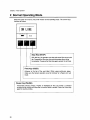
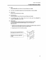
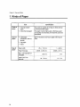
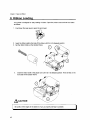
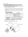
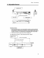
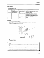
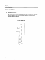
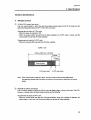
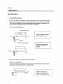
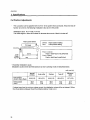
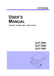
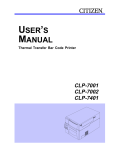
Chapter 4 Printer Adjustments
4 Adjustable Sensor
Adjustable knob
11I11I~ldlllllllll'llIllIllIllllllllIllllllllllIlllIllllIll
Upper guide rail
Operating procedure:
1,
Move the adjustable sensor to your required detection position by tuning the adjustable
knob, Measure your detection position beforehand, To set the detection position, align
the scale marking on top of the upper guide rail with the sensor position mark (yellow) on
the upper of the sensor, The movable range of the adjustable sensor is shown below,
2,
Set the liner and close the upper guide rail and set voltage to 3V,
For voltage selling, see Section 5: System Maintenance Mode, Chapter 2,
Left edge of paper
Omm
118 mm (max. paper width)
59 mm (sensor usable range)
I
----,
0
-[1-..
-
r
.. ....L
...
r--"
r,
_ _ _ _ _ _ .J
,
,
~-_
~
,
;,
,
...
r------,
--'
I
L.J
I[
p
-~
Adjustable sensor
movable range
49