1
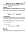
June 19, 2002
GFK-1512M
IMPORTANT PRODUCT INFORMATION
READ THIS INFORMATION FIRST
Product:
IC693 CPU Modules with Firmware Release 10.60
IC693CPU350-CG
IC693CPU360-CH
IC693CPU363-BF
Introduction
This document contains information that is not available in any other publication; therefore, we recommend you save it
for future reference. This document discusses firmware release 10.60, which fixes the problems listed in “Problems
Resolved by this Release” (page 4).
No new features are added by this release.
Hardware Identification
The following table shows the revision level of the circuit boards used in the current version of these CPUs.
CPU Catalog
Number
Circuit Board ID
IC693CPU350-CG
CX3A1 or
CX3B1
44A739579-G01R04 or later
44A749514-G01R00 or later
IC693CPU360-CH
CX3A1
CX3B1
44A739579-G01R04 or later
44A749514-G01R00 or later
IC693CPU363-BF
CX3A1
44A739579-G01R05 or later
Circuit Board Version
Firmware Upgrade Kits
If you wish to upgrade an existing CPU350 or CPU360 to firmware version 10.00, you may purchase the applicable kit
identified in the following table. All previous versions are capable of being upgraded.
Firmware Upgrade Kit Catalog Numbers
CPU Catalog Number
Firmware Upgrade Kit Catalog Numbers
IC693CPU350-(all versions)
44A747145-G06
IC693CPU360-(all versions)
44A747148-G07
IC693CPU363-BF
44A747766-G05
2
Important Product Information
GFK-1512M
Firmware Identification
CPU Catalog Number
IC693CPU350-CG
IC693CPU360-CH
IC693CPU363-BF
Motherboard
Firmware Version
Main:
R10.60 (38A1)
Boot: R9.00 (33A1)
Main:
R10.60 (38A1)
Boot: R9.00 (33A1)
Main:
R10.60 (38A1)
Boot: R9.00 (33A1)
Daughterboard
Firmware Version
N/A
N/A
Main:
R10.00 (49A1)
Boot: R2.00 (30A1)
Firmware Upgrade Hardware Requirements
Note:
The Model 350 and 360 CPU operating firmware is stored in FLASH memory. The firmware upgrade is
provided on a floppy disk and must be serially downloaded from a Personal Computer. An IBM AT personal
computer or better PC with a minimum 640K of RAM, one 3.5” floppy drive, MS-DOS version 3.3 or later (or
Windows 95 or later), a hard drive, and one RS-232 serial port is required. In addition, a serial cable and RS232/RS-485 converter are required. The following serial cable/converter kit is available from GE Fanuc:
IC690ACC901 Mini Converter (RS-232/RS-485) Kit with serial cable
Functional Compatibility
•
CIMPLICTY Machine Edition PLC Logic Developer version 2.11 or later, or VersaPro version 1.1 or later is
required to utilize the features introduced in release 10.00 firmware.
•
PLC Logic Developer, VersaPro version 2.00 or later, or Control software version 2.00 or later is required for C
programming.
•
Version 4.00 or later of the C toolkit must be used for C programming.
•
Control software version 2.00 or later must be used to take advantage of Sequential Function Chart (SFC)
subroutines.
•
Logicmaster software version 9.02 or later must be used to take advantage of the features introduced in firmware
release 9.00.
Important Product Information
3
GFK-1512M
Operating Notes
User Information Cleared when Upgrading Firmware
User information, consisting of program, configuration, CPU ID (used for SNP communications), and status tables in
RAM memory, will automatically be cleared if the CPU firmware in flash memory is changed. You will need to restore
these if upgrading firmware. A recommended procedure is to first back up your user information from RAM memory
to Flash memory. Then write your new firmware to Flash memory (firmware is stored in a different location in Flash
memory than that used for storing user information such as program, configuration, etc.). Finally, write your user
information back out of Flash into RAM memory. As an alternative, your user information (program, configuration,
etc.) can be restored from a computer-based backup program folder using your PLC programming software. The SNP
ID, if required, must be set separately using the programming software or the Hand-Held Programmer (HHP).
Option Module Revision Requirements
•
Ethernet Interface Module Compatibility. All IC693 Ethernet Interface (IC693CMM321) modules used with
these CPUs should be updated to IC693CMM321 firmware release 1.10 or later. This is also a requirement of the
TCP/IP Ethernet version of the MS-DOS programming software. During a Run Mode Store (Alt + S hot key
combination) of a large program block (greater than 14 kilobytes), the Ethernet module may time out, causing
communications to fail. Changing the Communications Window to Run-to-Completion mode, or storing the
program in Stop mode, will allow the store to take place successfully.
•
FBC Compatibility. FBC version 3 or later is required for these CPUs.
Writing to Flash Using the Windows PLC Programming Software
When writing very large programs to flash memory, it may be necessary to increase the Windows PLC programming
software request timeout value to avoid receiving a request timeout message. An upper bound of 25 seconds is typically
satisfactory
Storing Large Configurations
The IC693 PLC normally supports 20 DSM314 modules in a system. This number may be reduced by other modules in
the system, such as APM and GBC modules. It may also be further reduced if using datagrams that read the reference
or fault tables. If the configuration and user program are stored at the same time, the presence of either C blocks within
the LD program, or a C logic program may also affect the number of DSM314 modules that may be included in a
system. If the store fails, it may be possible to work around this problem by first storing the logic program and then
storing the configuration on a separate store request. The number of modules supported may be further reduced by the
size of CPU user memory.
No Model Number Checking with DOS-based programmer
The No Model Number Checking feature does not support storing a 311, 313, 321, 323 or 331 configuration to a
Release 9.0 or later CPU.
Simultaneous Load and Store
When operating with multiple programmers attached, if a store operation is initiated by one programmer, while a load
operation is already in progress, the load request will fail.
Transition Tables are not cleared when the reference tables are cleared.
The transition tables are not cleared upon clearing the reference tables through the programmer.
4
Important Product Information
GFK-1512M
Problems Resolved by this Firmware Release (10.60)
CPU won’t handle 11K byte smart module init file
With the new version of Horner PBM and the new version of VersaPro, both of which create and expect an 11K byte
init file, logic analyzer traces show that the data received from the SI30 on the module are incorrect. That is, the data
coming across the backplane was corrupted. A LOAD or VERIFY of the configuration works properly, so it appears
that the data within the PLC is correct.
Load of large (>32K) DSM zip files fails
Load greater than 32K through 364 (stored over SNP)
Failed with the following station manager log.
= log
<<< Exception Log >>>
Log initialized using valid RAM information
Log last cleared 01-JAN-2000 03:32:49.7
Date
Time
Event Count Entry
01-JAN-2000 03:33:17.2 8H 21H 00H 0024H 0202H 0000H 0001H 0000H
->01-JAN-2000 03:33:25.9 8H 1H 00H 0008H 0000H 0097H 002eH 0000H
Restrictions and Open Issues
Timing Issue with ALG220/221 Modules May Result in Incorrect %AI Values Read by CPU
A problem was found with the IC693ALG220/221F (and earlier versions) where the actual %AI values reported by the
card may exhibit erratic behavior (versions F and earlier may show this problem; the problem was fixed in version G or
later). Certain current or voltage levels within the input range applied to the card could cause the %AI values to report
incorrectly. The problem stems from the use of particular optocouplers, which may exhibit timing issues with these
CPU35x/36x modules. (NOTE: CPUs 341, 331, 321, 313, and 311 have not exhibited this problem.)
The IC693 PLC will generate a fatal fault if a ladder containing DOIO function block calls to a smart
module is repeatedly placed in RUN then STOP mode
A problem was found with the CPU where a ladder containing a call to a DOIO function block would cause the PLC to
run out of system memory. This is caused when the PLC transitions to run mode and back to stop mode several times.
If the configuration is stored, the system memory will be freed, and the PLC will resume normal operation.
IC693 PLC CPU may Develop Fatal Fault During Store of Folders with Large Configurations
The IC693 PLC CPU may generate a fatal fault during a store of a folder with an especially large configuration. This
may be made worse by storing a program and configuration at the same time, or by having datagrams from a
programmer present during the store.
PID Integral Contribution
The PID Integral Contribution is not calculated correctly with an integral rate of 0 or 1.
A CPU360 Configuration Stored to CPU352 may Cause Fatal Fault
If a CPU360 configuration file is stored to a CPU352, the PLC may generate a fatal fault when transitioning to run
mode.
Reading from an Invalid Flash Part may Cause a Watch Dog Timeout
If a corrupted flash part is read, the Watch Dog Timer on the PLC may be triggered. This can be fixed by completing a
valid flash store.
Important Product Information
GFK-1512M
Fatal Fault Occurs when Configuring a Module with the HHP Following a Maximum Size PLC Store
The IC693 PLC CPU may generate a fatal fault while attempting to configure a module with the Hand-Held
Programmer (HHP) following a maximum size store to the PLC.
Firmware Update Fail Following Power-up with Clear M/T and a Write to Flash
Firmware update may fail following a power-up with Clear M/T pressed on the Hand-Held Programmer and a write to
flash. Cycling power on the PLC will enable the upgrade to proceed.
Documentation
Instructions for using these two modules can be found in the latest version of the following manuals:
Hardware Description, Installation Instructions: IC693 Installation and Hardware Manual
General Configuration Instructions: IC693 PLC Programming Software User’s Manual
System Operation: IC693 PLC System Manual
System Operation and Instruction Set: IC693 PLC Reference Manual
5
6
Important Product Information
GFK-1512M
IC693CPU350 Data
CPU Type
Total Baseplates per System
Single slot CPU module
8 (CPU baseplate + 7 expansion and/or remote)
CPU 350
Load Required from Power Supply
670 milliamps from +5 VDC supply
ON
Processor Speed
25 MegaHertz
Processor Type
80386EX
Typical Scan Rate
.22 milliseconds per 1K of logic (Boolean contacts)
User Program Memory (maximum)
32K Bytes (not configurable)
Discrete Input Points - %I
Discrete Output Points - %Q
2,048
2,048
Discrete Global Memory - %G
1,280 bits
Internal Coils - %M
4,096 bits
Output (Temporary) Coils - %T
256 bits
System Status References - %S
128 bits (%S, %SA, %SB, %SC - 32 bits each)
Register Memory - %R
9,999 words
Analog Inputs - %AI
2,048 words
Analog Outputs - %AQ
512 words
System Registers (for reference table
28 words (%SR)
viewing only; cannot be referenced in user logic
program)
.
Timers/Counters
>2,000
Shift Registers
Yes
Built-in Serial Port(s)
1 (uses connector on PLC power supply). Supports SNP,
SNP-X slave protocols. Requires CMM module for
SNP/SNP-X master, CCM, or RTU (slave) protocol support.
Requires PCM module for RTU master support.
Communications
LAN – Supports multidrop. Also supports Ethernet, FIP,
Profibus, GBC, GCM, and GCM+ option modules.
Override
Yes
Battery Backed Clock
Yes
Interrupts
Supports the periodic subroutine feature.
Type of Memory Storage
RAM and Flash
PCM/CCM Compatibility
Yes
Floating Point Math Support
Yes, firmware-based in firmware releases 9.0 and later.
PS
PORT
OFF
7
Important Product Information
GFK-1512M
IC693CPU360 Data
CPU Type
Total Baseplates per System
Single slot CPU module
8 (CPU baseplate + 7 expansion and/or remote)
CPU 360
Load Required from Power Supply
670 milliamps from +5 VDC supply
ON
Processor Speed
25 MegaHertz
Processor Type
80386EX
Typical Scan Rate
.22 milliseconds per 1K of logic (Boolean contacts)
User Program Memory (maximum)
240K (245,760) Bytes. Note: Actual size of available
user program memory depends on the amounts configured
for the %R, %AI, and %AQ configurable word memory
types (described below).
Discrete Input Points - %I
Discrete Output Points - %Q
2,048
2,048
Discrete Global Memory - %G
1,280 bits
Internal Coils - %M
4,096 bits
Output (Temporary) Coils - %T
256 bits
System Status References - %S
128 bits (%S, %SA, %SB, %SC - 32 bits each)
Register Memory - %R
Configurable in 128 word increments, from 128 to 16,384
words with DOS programmer, and from 128 to 32,640
words with Windows programmer Ver. 2.2 or VersaPro
version 1.0.
Analog Inputs - %AI
Configurable in 128 word increments, from 128 to 8,192
words with DOS programmer, and from 128 to 32,640
words with Windows programmer Ver 2.2 or VersaPro
version 1.0.
Analog Outputs - %AQ
Configurable in 128 word increments, from 128 to 8,192
words with DOS programmer, and from 128 to 32,640
words with Windows programmer Ver. 2.2 or VersaPro
version 1.0.
System Registers (for reference table
28 words (%SR)
viewing only; cannot be referenced in user logic
program)
Timers/Counters
>2,000
Shift Registers
Yes
Built-in Serial Port(s)
1 (uses connector on PLC power supply). Supports SNP,
SNP-X slave protocols. Requires CMM module for
SNP/SNP-X master, CCM, or RTU (slave) protocol
support. Requires PCM module for RTU master support.
Communications
LAN – Supports multidrop. Also supports Ethernet, FIP,
Profibus, GBC, GCM, and GCM+ option modules.
Override
Yes
Battery Backed Clock
Yes
Interrupts
Supports the periodic subroutine feature.
Type of Memory Storage
RAM and Flash
PCM/CCM Compatibility
Yes
Floating Point Math Support
Yes, firmware-based in firmware release 9.0 and later.
PS
PORT
OFF
8
Important Product Information
GFK-1512M
IC693CPU363 Data
a47500
CPU Type
Total Baseplates per System
Single slot CPU module
8 (CPU baseplate + 7 expansion and/or remote)
P1
Load Required from Power Supply
890 milliamps from +5 VDC supply
P2
Processor Speed
25 MegaHertz
Processor Type
80386EX
Typical Scan Rate
.22 milliseconds per 1K of logic (Boolean contacts)
User Memory (total)
240K (245,760) Bytes. Note: Actual size of available
user program memory depends on the amounts
configured for the %R, %AI, and %AQ configurable
word memory types (described below).
Discrete Input Points - %I
Discrete Output Points - %Q
2,048
2,048
Discrete Global Memory - %G
1,280 bits
Internal Coils - %M
4,096 bits
Output (Temporary) Coils - %T
256 bits
System Status References - %S
128 bits (%S, %SA, %SB, %SC - 32 bits each)
Register Memory - %R
Configurable in 128 word increments, from 128 to
16,384 words with DOS programmer, and from 128 to
32,640 words with Windows programmer Ver. 2.2 or
later, or VersaPro version 1.0 or later.
Analog Inputs - %AI
Configurable in 128 word increments, from 128 to
8,192 words with DOS programmer, and from 128 to
32,640 words with Windows programmer Ver 2.2 or
later, or VersaPro version 1.0 or later.
Analog Outputs - %AQ
Configurable in 128 word increments, from 128 to
8,192 words with DOS programmer, and from 128 to
32,640 words with Windows programmer Ver. 2.2 or
later, or VersaPro version 1.0 or later.
System Registers (for reference table
28 words (%SR)
viewing only; cannot be referenced in user logic
program)
Timers/Counters
>2,000 (depends on available user memory)
Shift Registers
Yes
Built-in Serial Ports
3 (one uses connector on PLC power supply). Supports
SNP/SNPX slave (on all three ports) and RTU slave and
Serial I/O (on Ports 1 and 2). Requires CMM module
for CCM and PCM module for RTU master.
Communications
LAN – Supports multidrop. Also supports Ethernet,
FIP, Profibus, GBC, GCM, and GCM+ option modules.
Override
Yes
Battery Backed Clock
Yes
Interrupt Support
Supports the periodic subroutine feature.
Type of Memory Storage
RAM and Flash
PCM/CCM Compatibility
Yes
Floating Point Math Support
Yes, firmware-based
PS
PORT
CPU 363
ON
OFF
PORT 1
RS-232
PORT 2
RS-485
FRAME