1
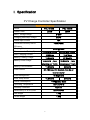
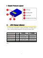
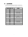
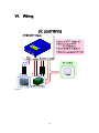
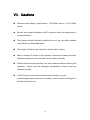
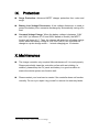
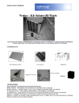
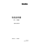
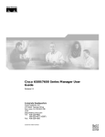
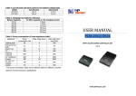
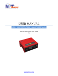
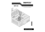
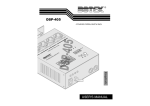
USER MANUAL PCL-1512M / PCL-1524M 200W / 250W MPPT charge controller with load control V.1.0 WWW.MPPSOLAR.COM Import Safety Instructions General Safety Instructions z Please follow all the instruction and warning markings in this manual and on the controller z Do not remove or bypass grounding pin. Make sure the surface of the controller is connected to earth. z Please check the appearance of controller before installation. Contact your sales agent if there is any obvious damage z Please keep the controller from moisture z Do not leave any heavy item on the top of the controller z To reduce the chance of short-circuits, use insulated tolls when installing or working with the controller z This controller should ONLY be installed and maintained by qualified professionals. z Please keep this manual for your future reference 2 Check the Controller and Parts The package should include a charge controller and user manual. Please contact your local dealer if there is any damage on the appearance of the charge controller or missing page in the manual. 3 Content I. Specification .............................................................................................. 5 II. Basic Product Layout ............................................................................... 6 III. LED Status Indicator ................................................................................ 6 IV. Load Switch ............................................................................................... 7 V. Charge Current Switch ............................................................................. 8 VI. Wiring ......................................................................................................... 9 VII. Cautions ................................................................................................... 12 VIII. Operation Instructions ............................................................................ 13 IX. Protection ................................................................................................. 14 X. Maintenance ............................................................................................ 14 4 I. Specification PV Charge Controller Specification Specification Summary Model PCL-1512M Rated Power PCL-1524M 200W 250W MPPT Voltage Range 6~50V Charging Start/Stop Voltage 6V/4V 15A Rated Input Current >85%/>90% Converter Efficiency /MPPT Efficiency 5Vdc @ 1min Sleeping Mode 12Vdc min.200AH 24Vdc min.100AH Max. Charging Current 16.66Amp 10.41Amp Battery Floating Charge 13.8V±5% 27.6V±5% 14.4V±5%,1min 28.8V±5%,1min charging per 10min charging per 10min 11.5V±5% 23V±5% Recommended Battery Spec Battery Pulse Charge Battery Low Shutdown Load Current DC 16Amax, Dry Contact, Can be an inverter starter 16 Segments Load Management Enter Sleep Mode 10.5V±5% 21V±5% <1W@sleep Mode Power Consumption Operating Temperature -20°C to 40°C Humidity Protection Optional Dimension (L x W x H) mm 200×142×50 Net Weight 1.7kg Gross Weight 1.8kg 5 II. Basic Product Layout III. LED Status Indicator The LED lights indicate MPPT charging, discharging, and battery status. Table 1 shows the relation between the LED lights and battery status. LED Status Indicator Status SOLAR (RED LED) Blinking BATTERY (RED LED) Blinking Stop discharge < 11.5V Stop discharge <23V BATTERY (RED LED) ON Low 12V-12.8V Low 24V-25.6V BATTERY (YELLOW LED) ON Normal 12.8V-13.8V Normal 25.6V-27.6V BATTERY (GREEN LED) ON Full > 13.8V Full > 27.6V LOAD (GREEN LED) Blinking PCL-1512M PCL-1524M Blinks once per second when charging Blinks once per second when load is normal Table 1. 6 IV. Load Switch Load switch manages discharging time based on requirement. Our product provides 16 segments load management – please see below, Discharge Mode(0/OFF, 1/ON) Load Output 0000 TEST mode for 5min 0001 2 hours on at night 0010 4 hours on at night 0011 6 hours on at night 0100 8 hours on at night 0101 10 hours on at night 0110 12 hours on at night 0111 Full on 1000 TEST mode for 5min 1001 2 hours on at day 1010 4 hours on at day 1011 6 hours on at day 1100 8 hours on at day 1101 10 hours on at day 1110 12 hours on at day 1111 Full on 7 V. Charge Current Switch The charging current switch can adjust current based on power. The set-up modes are defined as the followings, Discharge Mode(0/OFF, 1/ON) Charge Current 0001 5A 0010 10A 0100 15A 1000 20A 0000 25A 8 VI. Wiring Wiring Instructions: PV+/PV- Line:connect the output of solar panel to the PV+/PV- lines of the controller ---(14AWG, Blue(PV+)/Brown(PV-) 1) BAT+ Line:connect to the positive polarity (+) of a battery ---(10AWG, RED(+)) BAT+ Sensor Line:connect to the positive polarity (+) of a battery to detect its voltage ---(18AWG, RED(+)) BAT- Line:connect to the negative polarity (-) of a battery ---(10AWG、BLACK(-)) BAT- Sensor Line:connect to the negative polarity (-) of a battery to detect its voltage ---(18AWG、BLACK(-)) Discharge Control Signal Line:dry contact, can work as an inverter starter ---(14AWG*2、White、Orange) Ground Line:this line is for grounding to avoid damage from spikes, such as lightning strike ---(14AWG、Yellow and Green Stripe) 1 Please refer the following wiring charts. 9 VI. Wiring Figure 1 10 VI. Wiring Figure 2 11 VII. Cautions Recommended Battery Specification: 12V/200Ah above or 24V/100Ah above. Be sure the voltage of batteries and PV panels is within the range given in the specifications. The charge controller should be installed in a cool, dry, and well ventilated area without any flammable items. The length of battery wires should be shorter than 5 meters. Before connect PV panels to the controller, make sure a battery has been installed properly and the controller can be started normally. Please unwire the input terminal, and then, batteries before removing the controller - which could be damaged permanently if those steps are followed correctly. If the PV panel is not wired correctly to the controller, e.g. the positive/negative poles are wired reversely, a short circuit could happen or the fuse could burn out. 12 VIII. Operation Instructions Discharge Mode Options: 16 segments available. Please refer to the Load Switch section in this manual. Day/Night Mode Detection: the controller will switch to day/night mode based on the input voltage from PV panels。Therefore, the PV panels needs to be installed properly before this function starts to work. Day/Night Mode Switch: It takes the controller 10-20 minutes to determine that it’s daytime or nighttime. Please see the table below. Day Mode: The controller will discharge battery only during daytime. Night Mode: The controller will discharge battery only during nighttime. Detection Time – Normal first time after the Detection controller is started Time Testing Mode Immediately Immediately 5min Day Mode 20min 10min Based on Setup Night Mode 10min 10min Based on Setup Full On Mode 5s 5s Full On Discharge Mode 13 LOAD Discharge IX. Protection Surge Protection: Advanced MPPT charger protection from noise and surge Battery Low Voltage Disconnect: A low voltage disconnect is used to protect the battery from excessive discharge by automatically turning off a load. Constant Voltage Charge: When the battery voltage is between 13.8V and 14.4V (or between 27.6V and 28.8V based on model), the MPPT function will turns off (∗). Then, the charger will enter into a floating charge mode; when the battery voltage is over 14.4V/28.8V, the controller will change to a pulse charge mode – 1 minute charging per 10 minutes. X. Maintenance The charge controller only requires little maintenance if it is used properly. Please periodically clean the controller surface with wet clothing. In addition, please keep the PV panel and battery in a good condition to ensure the whole system can function well. Please contact your local service center if the controller does not function normally. Do not try to repair it by yourself or remove the warranty labels. ∗ The voltage accuracy will be within ± 5% range. 14