1
User Manual for the
HE693PBS106
PROFIBUS SLAVE
Second Edition
05 June 2003
MAN0221-02
PREFACE
05 JUN 2003
PAGE 2
PREFACE
This manual explains how to use the Horner APG Profibus Slave Module (HE693PBS106).
Copyright (C) 2003 Horner APG, LLC., 640 North Sherman Drive, Indianapolis Indiana, 46201. All rights
reserved. No part of this publication may be reproduced, transmitted, transcribed, stored in a retrieval
system, or translated into any language or computer language, in any form by any means, electronic,
mechanical, magnetic, optical, chemical, manual or otherwise, without the prior agreement and written
permission of Horner APG, LLC.
All software described in this document or media is also copyrighted material subject to the terms and
conditions of the Horner Software License Agreement.
Information in this document is subject to change without notice and does not represent a commitment on
the part of Horner APG, LLC.
Profibus is a trademark of Siemens, Inc.
LM90 and Series 90-30 PLC are trademarks of GE Fanuc.
Alspa 8000 and P8 are trademarks of CEGELEC.
For user manual updates, contact Technical Support:
North America:
(317) 916-4274
www.heapg.com
Europe:
(+) 353-21-4321-266
www.horner-apg.com
PAGE 3
05 JUN 2003
PREFACE
LIMITED WARRANTY AND LIMITATION OF LIABILITY
Horner APG, LLC. ("HE") warrants to the original purchaser that the Profibus Slave manufactured by HE
is free from defects in material and workmanship under normal use and service. The obligation of HE
under this warranty shall be limited to the repair or exchange of any part or parts which may prove
defective under normal use and service within two (2) years from the date of manufacture or eighteen
(18) months from the date of installation by the original purchaser whichever occurs first, such defect to
be disclosed to the satisfaction of HE after examination by HE of the allegedly defective part or parts.
THIS WARRANTY IS EXPRESSLY IN LIEU OF ALL OTHER WARRANTIES EXPRESSED OR IMPLIED
INCLUDING THE WARRANTIES OF MERCHANTABILITY AND FITNESS FOR USE AND OF ALL
OTHER OBLIGATIONS OR LIABILITIES AND HE NEITHER ASSUMES, NOR AUTHORIZES ANY
OTHER PERSON TO ASSUME FOR HE, ANY OTHER LIABILITY IN CONNECTION WITH THE SALE
OF THIS Profibus Slave. THIS WARRANTY SHALL NOT APPLY TO THIS Profibus Slave OR ANY
PART THEREOF WHICH HAS BEEN SUBJECT TO ACCIDENT, NEGLIGENCE, ALTERATION, ABUSE,
OR MISUSE. HE MAKES NO WARRANTY WHATSOEVER IN RESPECT TO ACCESSORIES OR
PARTS NOT SUPPLIED BY HE. THE TERM "ORIGINAL PURCHASER", AS USED IN THIS
WARRANTY, SHALL BE DEEMED TO MEAN THAT PERSON FOR WHOM THE Profibus Slave IS
ORIGINALLY INSTALLED. THIS WARRANTY SHALL APPLY ONLY WITHIN THE BOUNDARIES OF
THE CONTINENTAL UNITED STATES.
In no event, whether as a result of breach of contract, warranty, tort (including negligence) or otherwise,
shall HE or its suppliers be liable of any special, consequential, incidental or penal damages including,
but not limited to, loss of profit or revenues, loss of use of the products or any associated equipment,
damage to associated equipment, cost of capital, cost of substitute products, facilities, services or
replacement power, down time costs, or claims of original purchaser's customers for such damages.
To obtain warranty service, return the product to your distributor with a description of the
problem, proof of purchase, post paid, insured and in a suitable package.
ABOUT PROGRAMMING EXAMPLES
Any example programs and program segments in this manual or provided on accompanying diskettes are
included solely for illustrative purposes. Due to the many variables and requirements associated with any
particular installation, Horner APG cannot assume responsibility or liability for actual use based on the
examples and diagrams. It is the sole responsibility of the system designer utilizing the Profibus Slave to
appropriately design the end system, to appropriately integrate the Profibus Slave and to make safety
provisions for the end equipment as is usual and customary in industrial applications as defined in any
codes or standards which apply.
Note: The programming examples shown in this manual are for illustrative
purposes only. Proper machine operation is the sole responsibility of the
system integrator.
PREFACE
05 JUN 2003
PAGE 4
TABLE OF CONTENTS
PREFACE ..................................................................................................................................................... 2
LIMITED WARRANTY AND LIMITATION OF LIABILITY............................................................................. 3
ABOUT PROGRAMMING EXAMPLES ........................................................................................................ 3
TABLE OF CONTENTS ................................................................................................................................ 4
CHAPTER 1: INTRODUCTION ................................................................................................................... 6
1.1
General ........................................................................................................................................... 6
1.2
System Requirements: ................................................................................................................... 6
1.3
Physical Layout of PBS106: ........................................................................................................... 7
1.4
LED Operation of PBS106:............................................................................................................. 7
1.5
Profibus DP Connector................................................................................................................... 8
1.6
RS-232 Connector .......................................................................................................................... 8
1.7
PBS106 Status ............................................................................................................................... 9
1.1.7
PLC Status Bit Definition ......................................................................................................... 9
2 TECHNICAL SUPPORT ........................................................................................................................ 9
CHAPTER 2: INSTALLATION AND CONFIGURATION ............................................................................ 10
2.1
PBS106 Mounting Requirements ................................................................................................. 10
2.2
Configuring the PBS106 ............................................................................................................... 10
2.3
Status Bits..................................................................................................................................... 12
CHAPTER 3: WIRING DIAGRAMS ............................................................................................................ 13
3.1
Profibus Wiring ............................................................................................................................. 13
PAGE 5
05 JUN 2003
This Page Intentionally Left Blank
PREFACE
CHAPTER 1: INTRODUCTION
05 JUN 2003
PAGE 6
CHAPTER 1: INTRODUCTION
1.1
General
The Profibus Slave User Manual describes the operation, configuration, and physical
characteristics of the PROFIBUS Slave device. The Horner Electric HE693PBS106 provides the
GE Fanuc PLC with a flexible communications interface to PROFIBUS networks for
Decentralized Peripherals (DP).
The HE693PBS106 operates as PROFIBUS DP modules only. They do not support the other
types of Profibus (FMS, PA). The PROFIBUS utilizes a Master-Slave type of communication with
the HE693PBS106 functioning as the slave device. Decentralized Peripherals (The Slave)
include but are not limited to: input/output devices, drives, valves, and measuring transmitters.
DP’s are mainly used to connect programmable controllers to the above devices via a high speed
serial link. Baud rates of up to 12 MBd can be obtained through PROFIBUS.
Up to 32 devices (masters or slaves) can be connected in one segment without using repeaters,
or up to 64 devices can be connected using repeaters.
Master devices are used to determine the data communication on the bus. One master can
service several slaves. Several Masters can participate on the bus simultaneously, but a slave
can only receive outputs from one master.
The slave devices are peripheral devices that include input/output devices, valves, and drives.
Slaves do not have bus access rights and can only acknowledge received messages or send
messages to the master when requested to do so. Any master can read data from the Slaves.
All connected Slaves have the same priority.
1.2
System Requirements:
Note: The HE693PBS106 requires GE-Fanuc Series 90 / CEGELEC Series 8000 PLC
programming and configuration software for use.
The LogicMaster version of the Horner Electric Profibus Slave for 90-30 (HE693PBS106) allows
the incorporation of the Profibus slave module on a Series 90-30 rack that does not support
Cimplicty Control and/or does not require a “slot 1” CPU. An example of such a rack would be
the IC693CPU313. It is possible to use a Profibus Slave on these racks using the LogicMaster
software for configuration. There are, however, some limitations in the capabilities of this version
of the PBS106. The network data is limited to 1 to 16 words of input and 1 to 16 words of output.
An additional word of input is added to the PLC data for module status information.
PAGE 7
1.3
05 JUN 2003
CHAPTER 1: INTRODUCTION
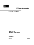
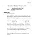
Physical Layout of PBS106:
PROFIBUS DP
OK
PROFIBUS
DP PORT
RUN
PWR
RS-232
SERVICE PORT
H E 693 P B S 106 # ###
H o rn e r E le c tric , In c .
PROFIBUS DP
SLAVE
Figure 1.1 - PBS106 Module (Front Cover and Side View)
1.4
LED Operation of PBS106:
There are three visible LED’s on the PBS106, the OK LED, RUN LED, and the POWER LED.
Various combinations of these LED’s will indicate different states of the Slave. See Table 1-1 for
the states indicated by the LED’s.
Table 1.1 – LED Operation
POWER LED
OK LED
RUN LED
Off
Yellow
Off
Red
Off
Green
Green
Red
Green
Green
Green
Green
Red
Blinking
between
yellow and
green
Yellow
Meaning
Module not receiving any power.
Module has good power, but has not received valid
configuration from CPU, and is not communicating
on the Profibus-DP network.
Module has good power, has received valid
configuration from CPU, but is not communicating
on the Profibus-DP network.
Module has good power, has received valid
configuration from CPU, and is communicating on
the Profibus-DP network.
A fault has occurred. Refer to the following
description to determine fault.
CHAPTER 1: INTRODUCTION
05 JUN 2003
PAGE 8
Table 1. 2 – Fault Conditions
Meaning
An error encountered during system initialization.
A mismatch between PLC I/O length and Profibus-DP
network map has occurred.
The blinking RUN light indicates a fault, to determine the fault; simply count the number of
green pulses (the LED will pause for 2 seconds, pulse green a number of times, then
repeat the cycle). Table 1-2 describes the fault as represented by the number of green
pulses.
Pulse Count
2
3
1.5
Profibus DP Connector
The 9-pin Profibus DP connector is for physical connection between the slaves and the master.
For further information on the cable and connectors, see Chapter 3.
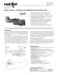
1.6
RS-232 Connector
The RS-232 Service Port is used to upgrade the firmware specific to the slave. This port uses a
standard RS-232 9-pin connector.
5
DTR
RXD
TXD
DCD
4
3
2
1
9
8
7
6
RI
RTS
CTS
DSR
Figure 1.2 - Pin-out for the
RS-232 connector.
PAGE 9
05 JUN 2003
1.7
PBS106 Status
1.1.7
PLC Status Bit Definition
Status Word Bits
2
Table 1.3 – PLC Status Bit Definition
Meaning
15-12
Baud Rate
11-10
DP State
9
8
7-4
3-0
On-line
PLC Config
Major Rev
Minor Rev
TECHNICAL SUPPORT
North America:
(317) 916-4274
www.heapg.com
Europe:
(+) 353-21-4321-266
www.horner-apg.com
CHAPTER 1: INTRODUCTION
Values
0= 12M
1= 6M
2= 3M
3= 1.5M
4= 500K
5= 187.5K
6= 93.75K
8= 19.2K
9= 9.6K
0= Wait PRM
1= Wait CFG
2= Data Exchange
3= Error
0= Off-line
1= Good PLC Configuration
0-9 Firmware Major Rev. level
0-9 Firmware Minor Rev. level
CH. 2: INSTALL/CONFIGURATION
05 JUN 2003
PAGE 10
CHAPTER 2: INSTALLATION AND CONFIGURATION
Note: The GSD Files can be found on the Horner Electric’s Website at www.heapg.com.
2.1
PBS106 Mounting Requirements
The PBS106 Module is designed to plug into any GE FANUC Series 90-30 or CEGELEC Alspha 8000
local slot. The PBS106 can be used with any version of the previously mentioned PLC’s. Please refer
to the GE Fanuc PLC Installation manual GFK-0356E for information on installing the module.
2.2
Configuring the PBS106
The PBS106 is configured for the PLC as a FOREIGN MODULE (ID 3).
Figure 2.1 – Configuration Screen
The following fields of the Foreign Module screen must be completed for the network configuration.
Byte 1 =
Byte 2 =
Byte 3 =
Byte 4 =
Byte 5 =
Byte 6 =
Bytes 7 - 16 =
00000001
00000000
01H - 7DH
00H
01H - 10H
01H - 10H
00H
Always 1
Always 0
Hex value if station ID 1 - 125
Always 0
Hex value of the number of Inputs Words 1 - 16
Hex value of the number of Output Words 1 -16
Always 0
PAGE 11
05 JUN 2003 CH. 2: INSTALL/CONFIGURATION
EXAMPLE:
1
B
Figure 2.2 – Configuration Screen (Example)
Byte 3 = 14 hexadecimal = Slave Station address of 20 decimal.
Byte 5 = 0B hexadecimal = 11 words of Inputs
Byte 6 = 01 hexadecimal = 1 word of Output
The network data below (%I, %Q, %AI and %AQ) must be mapped to PLC references and could be
done in the following manner:
%I Ref Adr
%I Size
%Q Ref Adr
%Q Size
%AI Ref Adr
%AI Size
%AQ Ref Adr
%AQ Size
:
:
:
:
:
:
:
:
%I0001
16
%Q0001
0
%AI0001
1
%AQ0001
11
Note: Either 1 word or 16 bits of data must
be added to the inputs. The status will
always be the first 16 bits of input data.
This would configure 16 %I’s starting at %I0001 and ending at %I0016 as status bits. 0 %Q's, 1 %AI at
%AI1, and 11 %AQ’s starting at %AQ1 and ending at %AQ11. The Module status bits can either be
configured as 16 %I’s or 1 word of %AI’s.
It is important to remember that Bytes 5 and 6 are used to configure the number of network data words
and the PLC data is configured by setting the reference addresses to the proper data lengths. For
instance if the network is set up for five words of outputs (by setting byte 6 to five) then the PLC data
must be set to five outputs as well. This can be done by setting up the %Q’s to a size of 80 bits or by
setting the %AQ’s to a size of five words, or any combination of %AQ’s and %Q’s.
CH. 2: INSTALL/CONFIGURATION
2.3
05 JUN 2003
PAGE 12
Status Bits
It is also important to remember that there has to be 16 bits (1 word) of PLC data set aside for status
bits. This can be done by setting aside 16 %I’s or 1 word of %AI’s. In order to insure this is done there
should always be 16 more bits of input data (or 1 more word of input data) configured in the PLC then
there is for the network data.
Example: If there are eight words of inputs configured at Byte 5 then there should be either nine
%AI’s configured or eight %AI’s and 16 %I’s making up a total of nine words (eight words for
network data and one word for status data). Even if there are no inputs configured across the
network (Byte 5 = 0), there must still be 16 bits (1 word) of data set in the PLC.
Note: %I data can be combined with %AQ data or %AI data can be combined with %Q data.
PAGE 13
05 JUN 2003
CH. 3: WIRING DIAGRAMS
CHAPTER 3: WIRING DIAGRAMS
3.1
Profibus Wiring
The following information covers the assembling of the cable for use with the DP port on the
PBM100 and PBS106 modules.
a. The HE693PBS106 uses a 9-pin D sub plug connector for its DP port. The pin assignment of
the Profibus plug connector and the wiring are shown below.
Station 1
Station 2
RxD/TxD-P
3
3
V+
6
6
DGND
5
5
RxD/TxD-N
8
Shielding
8
Protective Ground
Figure 3.1
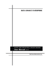
b. It is necessary to terminate both ends of the network. Both terminations must have power to
them to insure proper operation of the network. Figure 3-2 illustrates the correct connection for
the termination resistors.
VP(6)
Line Termination
390 Ohm
(Already on Profibus
Mainboard)
A-Line (3)
220 Ohm
B-Line (8)
390 Ohm
GND(5)
Figure 3.2
NOTE: Figure 3.2 is for illustrative purposes only. Cabling and connectors should be PTO
approved to achieve the desired performance results. See Section 3.1.3 for recommended
part numbers.
CH. 3: WIRING DIAGRAMS
05 JUN 2003
PAGE 14
c. The shield braiding and shield foil (if shield foil is present) must be connected to protective
ground on both sides. There must also be good conductivity via shield clamps covering as large
an area as possible. In addition, it is recommended that the data lines be kept separate from all
high-voltage cables.
Other considerations when wiring the Profibus network are:
a. In a Profibus network, up to 32 stations (master or slaves) can be connected per segment
without the addition of repeaters. If more that 32 stations are desired, repeaters must be used.
The repeaters are used to connect individual bus segments together.
b. The maximum cable length depends on the transmission speed. The specified cable length
can be increased by the use of repeaters; however, the use of more than three repeaters in
series is not recommended.
c. The following cable length specifications are based on type-A cable with 135 to 165 Ohm
impedance, less than 30 pf/m capacity, a loop resistance of 110 Ohms/Km, a wire gauge of
.64mm, and a conductor area of 0.34mm².
Table 3.1 Baud Rate / Distance
Baud Rate(bit/sec)
9.6K
19.2K
93.75K
187.5K
500K
1.5M
12M
Distance/Segment
1200m
1200m
1200m
600m
200m
200m
100m
d. For data transmission speeds of greater than 500 kbit/sec, Stub lines should be avoided.
There are plug connectors available on the market that permit data line A and data line B to be
connected directly to the plug connector.
3.2
Recommended Part numbers:
It is highly recommended that the following cable and connectors be used for high speed data
transmissions. Both Cable and Connector part numbers are Siemens part numbers.
a. Connectors:
Extra 9-pin DSUB for
easy cable stacking.
6ES7-972-0BB10-0XAO
6ES7-972-0BA10-0XAO
Figure 3.3 - Connectors
b.
Cable: Part Number 6XV1-830-OAH10