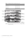
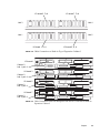
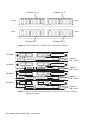
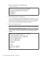
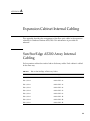
1
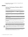
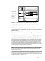
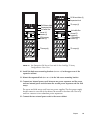
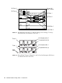
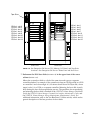
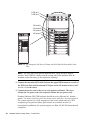
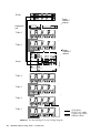
4. Connect two external power cords to the server cabinet.
The Database Platform 420/3 hardware should have two dedicated AC breaker
panels. The cabinet should not share these breaker panels with other, unrelated equipment.
The system requires two L30-R receptacles for the server cabinet, split between two
isolated circuits. For international installations, the system requires two Blue 32A
IEC309 (International) receptacles.
5. Connect the server cabinet power cords to the appropriate receptacles.
6. Power on the disk arrays; do not connect them to the server at this time.
7. Using a null modem cable, connect a CRT, laptop, or serial port B on another Sun
Server to serial port A of the VOS server. If you are connecting a computer that is
running the Solaris Operating Environment, to get the console window, type:
tip hardwire
8. Power on the server. The power-on self-test will run about 20 minutes. Once the
system banner and “initializing memory” message are displayed, press STOP-A to
get the ok> prompt.
9. At the ok> prompt, change the following values:
setenv auto-boot? false
setenv diag-level min
setenv diag-switch? false
10. Connect two fiber optic cables between the server and the disk arrays ( FIGURE 3-1).
11. Connect the two copper loop cables to the disk arrays (FIGURE 3-3).
To FC-AL slot 2
MIA
Loop
cables
To FC-AL slot 1
MIA
FIGURE 3-3
Loop Cabling and Sun StorEdge T3Array to Sun Enterprise 420R Server
Cabling—Rear View
Chapter
15