1
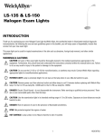
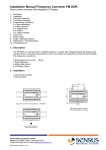
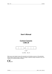
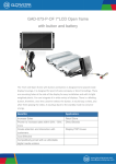
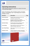
POWER SUPPLY SOURCES
SERIES SSG
SSG 1,5 SSG2,5 & SSG5
Instruction Manual
July 12, 2006
SSG-0101
All the information contained in this document may be modified without prior warning.
IMPORTANT SAFETY
INSTRUCTIONS
Electric Safety Measures
No one should work alone in potentially hazardous situations.
A high short-circuit current from conductive materials can cause serious burns.
A licensed electrician must be present for permanent installation of equipment with hardwiring.
Check that the power supply cables, plugs and sockets are in good condition.
Do not use any kind of metal component without first unplugging the equipment.
Batteries
Batteries should be recycled. Leave the battery in a suitable recycling bin or return it to
the supplier in the original packaging of the new batteries. Consult the new battery
instructions to obtain more information on this.
Do not dispose of batteries by throwing them in fire, as they could explode.
Do not open or cut batteries; they contain an electrolyte that is toxic and harmful to the skin and
eyes.
In order to prevent personal injury caused by hazardous currents, avoid wearing wristwatches
and jewelry such as rings when replacing batteries. Use tools equipped with insulated handles.
When replacing batteries, use the same number and type of batteries installed in the equipment.
Consult your distributor to obtain information on battery equipment replacement and recycling
batteries.
SSG-0101
ZetaAlarm Systems
1
Table of Contents
Installation of Series SSG power
supply sources
1
2
3
SSG-0101
3
Checking the power supply source
3
Checks prior to installation
4
Protection against transient interferences
4
Cleaning
4
Mounting Series MPS
5
LED Description and
Operation
6
Features of SSG Power Supply
Sources
7
Fault Relay
8
Control Unit Connectors
9
LED Description
10
Specifications
11
ZetaAlarm Systems
2
1. INSTALLATION OF SERIES SSG
POWER SUPPLY SOURCES
It is easy to install and start operating the Series SSG
power supply source if you follow the procedures
described in this manual.
Read the instructions in this manual carefully to
prevent anomalies in the power supply source.
Checking the power supply source.
Before installing the Series SSG power supply source,
you should make some checks.
The following procedure indicates what should be
done in the event that the equipment has been
damaged after leaving the factory, or if the user has
any doubts about the quality of any ordered element.
1. If, after unpacking the Series SSG power supply
source and making a visual inspection, you find that it
has been damaged in any way, YOU SHOULD NOT
carry on with installation, but rather you should contact
the supplier for instructions on how to return and
replace the product.
Likewise, if during installation the product does not
respond properly, immediately contact your supplier.
2. It is important that you note the relevant details in
your complaint, the date on which you received the
product, the conditions of the package, and the name
of the contact person of the supplier firm.
. When the product has to be returned to the supplier,
it is recommended that the original packaging be used
whenever possible.
WARNING!!!
TAKE THE NECESSARY PRECAUTIONS WHEN HANDLING EQUIPMENT SENSITIVE TO ELECTRICAL
DISCHARGES
SSG-0101
ZetaAlarm Systems
3
Checks Prior to Installation
Before selecting a place to install the power supply source,
YOU SHOULD make sure that:
a) The ambient temperature stays between:
-5 ºC and 40 ºC
b) The relative humidity is less than:
93% (not condensed)
c) YOU SHOULD NOT locate the equipment in a place
exposed to high levels of humidity.
d) YOU SHOULD NOT locate the equipment in places
exposed to vibrations or blows.
e) YOU SHOULD NOT locate the equipment in places where
it is hard to access internal equipment and hardwiring
connections.
Protection against transient interferences.
Just like all electronic equipment, this system may function
irregularly when subject to electrical discharges. Although no
system is completely immune from electrical discharges, a
proper Earth connection will make the equipment less
susceptible.
The use of exterior hardwiring without anything to anchor it is
not recommended, as this would increase the system’s
susceptibility to electrical discharges.
The power supply system should be wall mounted so that the
front panel with the LEDs is clearly visible. The height with
respect to the floor should be chosen so that the front panel is
at eye level (approximately 1.5 m).
Cleaning
The power supply source box should be periodically cleaned
with a soft, moist rag that does not shed fluff.
Do not use solvents.
SSG-0101
ZetaAlarm Systems
4
Mounting the Series SSG
When you have a suitable location for the Series SSG power supply source, follow the instructions
indicated below:
1. Hold the rear box in the right position, supported on the wall, and mark the position of the screw holes,
making sure that the center one is leveled.
The following illustration shows the box and the screw holes through the back.
Do not use the rear box as a guide when drilling the holes!
2. Drill the holes in the wall.
3. Prepare the necessary openings to feed through the cable.
4. Screw the equipment’s rear box to wall using the holes in the box and the proper screws.
SSG-0101
ZetaAlarm Systems
5
2. LED DESCRIPTION AND OPERATION
FRONT
PANEL:
SERVICE
PRIMARY POWER SUPPLY FAULT /
BATTERY CHARGER FAULT
BATTERIES NOT CONNECTED FAULT /
LOW BATTERY WARNING
GENERAL FAULT
INTERNAL LEDS:
EARTH SHUNT
MAINS PRESENCE
SYSTEM FAULT
SSG-0101
ZetaAlarm Systems
6
Features of the Power Supply Sources
SSG series.
The SSG1,5 SSG2,5 and SSG5 power supply sources have been
designed in accordance with standard EN54-4 to supply support
power to fire control systems.
The Series SSG power supply source has been designed to operate
with a universal input range of 90 to 264 VAC and frequencies
between 47 and 440 Hz. There is no need to change the voltage; the
source self-adjusts to the primary power supply conditions.
The two source models are similar; they are composed of a power
supply module of 45W , 65W and 2 x 65W for supply sources
SSG1,5 SSG2,5 and SSG5, respectively, and an electronic control
module that provides all primary and secondary (batteries) power
supply source supervision.
The power supply sources can supply up to 630 mA (SSG1,5), 1 A
(SSG2,5) or 2 A (SSG5) of current in each of their two outputs PS01
and PS02. If the sum of currents is needed to supply a single load,
the positive of both outputs should be connected in parallel:
LOAD
The negative is common in the control board and thus does not need
to be bridged.
SSG-0101
ZetaAlarm Systems
7
Fault Relay
The power supply source is provided with a fault relay to indicate
any anomaly to a remote control unit. On idle, this relay is energized
to indicate normal operation; if any fault occurs, it is immediately
triggered except in the event of a 220 Vac mains power supply loss,
which is indicated after a delay of some 8 minutes in order to
prevent failures due to intermittent blackouts.
Fault Relay Operation
Connector J4 (FAULT) with three terminals
Terminal 1 (Left) C common
Terminal 2 (Center) NO or normally open
Terminal 3 (Right) NC or normally closed
The fault relay functions as follows:
Stop control (no power) or indicating fault
Between C and NC —> continuity
Between C and NO —> circuit open
Control in fault-free operation, i.e. NORMAL STATE
Between C and NC —> circuit open
Between C and NO —> continuity
SSG-0101
ZetaAlarm Systems
8
Control Unit Connectors:
There are four connectors at the top of the Control Unit:
OUTPUT 1:
PSO1 (+) Output 1 positive
PSO1 (-) Output 1 negative
OUTPUT 2 :
PSO2 (+) Output 2 positive
PSO2 (-) Output 2 negative
FAULT RELAY:
FAULT (C) Fault relay common
FAULT (NC) Contact normally closed
FAULT (NO) Contact normally open
MAINS IN:
MAINS IN ( ) Equipment earth
MAINS IN (L) Input phase
MAINS IN (N) Input neutral
There is 1 connector at the bottom of the control unit:
BATTERY IN:
IN BAT (+) Battery positive
IN BAT (-) Battery negative
SSG-0101
ZetaAlarm Systems
9
LED Description:
EXTERNAL LEDS:
POWER SUPPLY LED
Green LED that turns on when the control unit is providing
service through either of its two outputs.
PRIMARY POWER SUPPLY FAULT/
BATTERY CHARGER FAULT LED
Yellow LED:
It turns on without blinking if no power is received from the
converter, either because of a lack of mains in or else
converter failure.
It blinks when the control detects a malfunction of the
charger block in the control unit.
BATTERIES NOT CONNECTED FAULT/LOW BATTERY
WARNING LED.
Yellow LED:
It turns on without blinking when the batteries are
disconnected, either because of a connection fault or else
because they are at low discharge level and the control
disconnects them for protection.
It blinks when the batteries are at the last level of discharge
before disconnection
GENERAL FAULT LED
Yellow LED that turns on when there is a fault in the power
supply source. If this indication is triggered, the fault relay
will also be triggered.
INTERNAL LEDS:
EARTH SHUNT LED
This lights up when the equipment has detected an earth
shunt, depending on the position of the bridge in J1. If the
bridge is in place, earth shunts are supervised.
Solution for the earth shunt => Check that there is no shunt
between Earth and outputs 1 and 2 (+) and (-)
SYSTEM FAULT LED
The microprocessor of the power supply source is not
functioning properly.
MAINS OK LED
This lights up if mains power reaches the control board.
SSG-0101
ZetaAlarm Systems
10
3. SPECIFICATIONS
Dimensions:
380 mm wide x 410 mm high x 97 mm deep.
Source Power:
130 W (SSG5) 65 W (SSG2,5) 45 W (SSG1,5)
Input voltage:
Universal 90-264 Vac 47-440Hz
Maximum absorbed current:
1.6 Amp.
Efficiency:
80%.
Output voltage:
27 Vdc protected against over-voltages and short-circuits.
Power supply outputs:
2.
Connection terminals:
Terminal for 2.5 mm cable.
Maximum current per output:
630mA (SSG 1,5)
Battery charge current:
300mA (7 Amp/hour) / 600mA (17 Amp/hour)
1 A (SSG 2,5)
2 A (SSG 5)
Charges batteries to 80% in less than 24 hours and to 100% in
less than 48 hours.
Faulty Relay:
Contacts C, NO, NC maximum 1 Amp/24Vdc.
Energized in normal state.
State indication LEDs:
4 external 5 mm + 3 internal 5 mm.
Space for batteries:
2 x 17 Amp/hour.
Tube inlets:
Ø 21 mm
Earth Shunt Supervision
2 levels (intermediate, without supervision)
Conforms with safety standards:
Designed as per EN54-4; UL1950; TUV EN60950 and
Standards EMC, EN55022, IEC1000-4-2,3,4,5 IEC1000-3-2.
SSG-0101
at the top.
at the top rear.
ZetaAlarm Systems
11