1
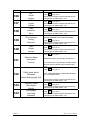
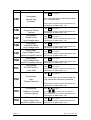
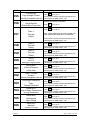
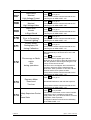
Page 1 / 46 C 306.36 User’s Manual Control Console C306.36 n. 0077 Ver. ENG - Rev J5 While every care is taken to ensure the description and illustration accuracy in this publication, factory reserves itself the right to make any change in equipment design considered to be in the interest of our customers without noticing it. C 306.36 (0077 – Ver E – Rev J5) NOTICE The safety of both patient and operator was a major consideration in the design and manufacturing of this equipment. The equipment will function reliably when operated, maintained, and repaired according to the instructions in this manual. Misuse, however, could result in hazards to patient, operator and/or equipment. CONFORMITY CERTIFICATION Manufacturer certifies that X-ray generator series R306.3x - R306.4x is in accordance to European Medical Directive MDD 93/42/CEE, and it meets all the requirement asked by tubes or subassemblies that complies with this regulation, only if controls and requirement are strictly observed and tubes calibrated in the working range specified by tube X-RAY DIAGNOSTIC SYSTEMS MECHANICAL and ELECTRICAL SAFETY All moveable assemblies and parts of the unit should be carefully operated and routinely inspected according to the Operator and Maintenance Manuals. Only properly trained and qualified personnel should have access to any internal components; before opening any access door be sure that line disconnect witch is open. DO NOT REMOVE the high tension cables from the X-ray tube housing or high tension generator until main and auxiliary power supplies have been disconnected. Failure to comply with the above may result in hazard to operator, patient, and/or equipment. Electrical Grounding Instruction Equipment when installed must comply IEC 601-2-7 grounding requirements, it must have a protection ground using a specific separate ground cable. The neutral side of the line is not to be considered the heart ground. DIAGNOSTIC X-RAY DEVICES IONIZING RADIATION WARNING Ionizing radiation can be dangerous for both the patient and the operator if safety regulation are omitted. Only specifically trained people can operate ionizing radiation equipments, following the on-site radiation directive according to general safety rules. C 306.36 (0077 – Ver E – Rev J5) C 306.36 (0077 – Ver E – Rev J5) SUMMARY SUMMARY .................................................................................................................................... 5 1. GENERALS...................................................................................................................... 7 1.1. Introduction .................................................................................................................. 7 1.2. Technical Characteristics............................................................................................. 7 1.3. Configuration................................................................................................................ 7 1.3.1. User’s Interface........................................................................................................ 7 1.4. Programmed Memory (Anatomical Technique) ........................................................... 8 1.5. User selection – Free Technique ................................................................................. 8 1.6. Automatic Exposure Control Technique ...................................................................... 8 1.7. Working Place Selection .............................................................................................. 8 1.8. Technical Characteristics............................................................................................. 9 1.9. Identification Data Sheet............................................................................................ 10 2. Controls .......................................................................................................................... 13 2.1. Generator Switch ON/OFF......................................................................................... 13 2.1.1. Control Electronics Switch ON .............................................................................. 13 2.1.2. Power Electronics Switch ON................................................................................ 13 2.1.3. Generator Switch OFF........................................................................................... 13 2.1.4. Reload Installation Condition................................................................................. 13 2.2. Main Screen ............................................................................................................... 14 2.3. Generator Status........................................................................................................ 15 2.4. Ionizing Radiation Emission Indication ...................................................................... 17 2.5. Warning Messages .................................................................................................... 17 2.6. Alarm Messages ........................................................................................................ 19 2.7. Working Station Selection.......................................................................................... 25 3. Intermittent Mode ........................................................................................................... 30 3.1. Radiographic Technique ............................................................................................ 30 3.1.1. Three Points Technique ........................................................................................ 30 3.1.2. Two Points Technique ........................................................................................... 31 3.2. Focal Spot Selection .................................................................................................. 31 3.2.1. Automatic Exposure Control Technique ................................................................ 32 3.3. Automatic Exposure Control Option........................................................................... 34 3.3.1. AEC controls.......................................................................................................... 34 3.4. LAST EXPOSURE DATA SUMMARY WINDOW ...................................................... 36 3.5. Intermittent Mode Data Programming........................................................................ 37 3.5.1. Programmed Memory Selection ............................................................................ 37 3.5.2. APR Program Store in Memory ............................................................................. 38 3.6. Continuous Mode (*RF version only) ......................................................................... 39 3.7. Auxiliary Functions ..................................................................................................... 40 3.8. Other Symbols ........................................................................................................... 41 4. SAFETY NOTICE............................................................................................................. 1 4.1. General Information ..................................................................................................... 1 4.2. Safety ........................................................................................................................... 2 4.2.1. Safety against Explosion ......................................................................................... 2 C 306.36 (0077 – Ver E – Rev J5) 4.2.2. Safety against ionizing radiation.............................................................................. 2 4.2.3. Automated Procedures and Device periodic test .................................................... 2 4.2.4. Cleaning................................................................................................................... 2 4.3. Performance and Safety Tests .................................................................................... 2 4.3.1. Daily Tests ............................................................................................................... 2 4.3.2. Monthly Tests .......................................................................................................... 3 4.3.3. Annual Service......................................................................................................... 3 C 306.36 (0077 – Ver E – Rev J5) 1. GENERALS 1.1. Introduction R306.3x microprocessors controlled series of X-Ray Generator have been developed according to conventional radio-diagnostics needs. Repetitive operations have been reduced using a new concept of intuitive Anatomical Programming Techniques. Designers always take in consideration the easy and intuitive interaction between man and device during the development process of this products All X-ray parameters are freely changeable, and can be user-stored in memory associated with a strings of characters freely selectable for quick retrieve. 1.2. Technical Characteristics R306.3x microprocessors controlled series of X-ray generator series includes several version of high frequency generators; the common characteristics are listed below. • Microprocessors controlled, network connected modular units • Intuitive Anatomic programming • R306.3x power output 40 - 50 - 65kW (High frequency - High Voltage Rectification) • Automatic Mains Voltage Drop Compensation • Intermittent working modes: • Automatic Exposure Control • Anatomical (APR) including Automatic Exposure Control • Free technique, including Automatic Exposure Control • Easy and Intuitive parameters change • Touch View interface (Touch Screen panel) • 1,2,3 points techniques • X-Ray Time & mAs pre-indication in kV/mA/s technique. • Actual Exposure Time display in Automatic Exposure Control mode (1 or 2 points). • Tube thermal load indication in Relative and Absolute format 1.3. Configuration R306.3x microprocessors controlled series of X-Ray Generator always includes the Power Rack (HV Transformer, Power Electronics and Control Electronics), and, as option, a Touch Screen Control Console for User Interaction. 1.3.1. User’s Interface User’s Interface is realized using a Graphic Interface on Touch Screen industrial class computer. All the information and selections are made through graphic virtual Selectors and Graphic Displays on the control console. C306.36 Control Console permits all the working techniques (1-2-3 points) as well as the technique with automatic exposure control and prefixed anatomical programs. The Control Console is connected to the microprocessor located in the power rack via Controlled Area Network Bus (CANBus) over a cable carrying all the necessary machine status information. All the functions are controlled via the various microprocessors standing on the network during all the working phases, the operator is run time informed of the “machine status ” in progress using icons and color lights. C 306.36 (0077 – Ver E – Rev J5) 1.4. Programmed Memory (Anatomical Technique) The term “Program” stands for an series of values stored in a computer location in which it is described the way the generator have to be set for the specific job. Every program is associated with two 12 characters strings for easy user recall. In every program are stored all the useful parameters such as kV, mA, time, working stations, predisposition for AEC, X- Ray tube, continuous mode preset and so further. These values can be adapted to three patient sizes according to its structure (normal, thin, obese) using the proper control. At any time, the pre-programmed parameters can be corrected on the control console according to the operator decisions. The programs available are as follows: • 12 Programs per screen • 2 banks per working station: 24 programs per working station • 4 working station on R306.4x or 4 working station on R306.3x. For a total of 96 memory location on 3 patients: 288 programmable working ways 1.5. User selection – Free Technique Every single modification of a programmed value changes the generator status to “Free Technique”: the starting values are the ones memorized in an anatomic program, freely changeable. 1.6. Automatic Exposure Control Technique Automatic exposure control chamber is automatically chosen when the associated working station is selected. Up to three dominant zones are freely selectable. Up to three different film/screen combination (Slow Speed High Resolution, Normal Speed Medium Resolution, High Speed Low Resolution, for example). The Automatic Exposure calibration process is performed by technical service during generator installation, the calibrated darkness can be modified by user needs in seven different timing steps from 50% to 200% of the nominal timing value. A user selectable mAs limit can be runtime selectable for special regulation requirements. Exposure technique (1 or 2 points) are set during generator installation according to user’s specifications. 1.7. Working Place Selection In Anatomic technique, the working station is automatically set according to the exam selected. In free Technique or in Programmed technique, the working station is selected according to the user working way through on-keyboard virtual pushbuttons. C 306.36 (0077 – Ver E – Rev J5) 1.8. Technical Characteristics NOMINAL MAXIMAL THROUGHPUT HIGH VOLTAGE WAVEFORM TUBE VOLTAGE IRRADIATION TIME FLUOROSCOPY (RF version only) AUTOMATIC EXPOSURE CONTROL X-RAY TUBE WORKING STATION HOSTING C 306.36 R306.34 R306.35 R306.36 400mA 500mA 630mA @ @ @ 100kV 100kV 100kV Continuous: High Frequency Continuous Adjust from 1ms to 6s in R’10 step scale kV and mA chained from 50kV to 100/110/120kV up to 5 mA AEC Semiconductor or Ionizing Chamber up to 2 chambers The complete standard bifocal tube library already present on other products 4 3 on Bucky Reply 1 Direct Radiography On a standard PC using ODEL NAVIGATOR program (0077 – Ver E – Rev J5) 1.9. Identification Data Sheet CONFORMITY to GENERAL MD STANDARD REFERENCE STANDARDS MDD 93/42/CEE CONFORMITY to PARTICULAR STANDARD IEC 601-1:1988 + A1:1991 + A2:1995 IEC 60601-2-7:1998 Odel S.p.A. Via Sartirana,12 Monza (MI) – Italia MANUFACTURER NAME MANUFACTURER’ s PRODUCT TRADE NAME R306.34 (40HF) R306.35 (50HF) R306.36 (65HF) Dealer’s PRODUCT TRADE NAME USER CONTROL CONSOLE C306.36 Other O-XRLink compatible device MANUFACTURING DATE R306.34 NOMINAL MAINS VOLTAGE NOMINAL MAINS FREQUENCY MAXIMUM POWER ABSORBED MAXIMUM APPARENT NOMINAL RESISTENCE (SUPPLY IMPEDANCE) MAINS CURRENT FUSES OR DEVICE 60 kVA 54 kW 75 kVA 63 kW 0,30 Ohm 0,20 Ohm COMPULSORY -10% .. +10% AUTOMATIC on admitted mains drop interval 40 kW 50 kW MD CLASS and TYPE Class I Type B PROTECTION INDEX IPX0 INTERMITTENT MODE (nominal maximum power output) CONTINUOS MODE (RF version) 98 kVA 82 kW 60 A delayed (fuses) or 63 A C-curve (magnetothermal circuit breaker) MAINS DROP ADMITTED MAXIMUM POWER OUTPUT R306.36 50-60 Hz GROUND COMPENSATED MAIN DROP R306.35 400 Vac Three-phase 400mA @ 100kV 65 kW 500mA @ 100kV 630mA @ 103kV 5mA @ 120kV COOLING REQUIREMENT CONTROL CONSOLE 95 kcal/h POWER RACK 930 kcal/h NOMINAL TUBE VOLTAGE 150 kV Intermittent Mode 120 kV Continuous Mode (RF Version) C 306.36 (0077 – Ver E – Rev J5) Intermittent Mode NOMINAL MAXIMUM TUBE CURRENT 400mA @ 100kV 500mA @ 100kV 630mA @ 103kV Continuous Mode (RF Version) 5mA MAXIMUM CURRENT TIME PRODUCT 600 mAs MINIMUM CURRENT TIME PRODUCT 0,4 mAs SHORTEST IRRADIATION TIME C 306.36 0,001 s (1ms) (0077 – Ver E – Rev J5) C 306.36 (0077 – Ver E – Rev J5) 2. Controls 2.1. Generator Switch ON/OFF 2.1.1. Control Electronics Switch ON Press I key on control console to switch on the control electronics. A welcome message will appear on the control console screen. 2.1.2. Power Electronics Switch ON Switch on the Power Electronics on welcome screen, pressing key . Since the power part is switched on it is possible to modify the parameters and recall a stored program. 2.1.3. Generator Switch OFF Press o key on control console to switch off the generator. Immediately is switched off the power electronics, after a few seconds it is switched off also the control electronics including the control console. 2.1.4. Reload Installation Condition If on initial screen (the welcome dialog box) appear the following key the and doesn’t appear key the generator has lost the actual configuration. It is possible to reload the initial configuration pressing key, key appear and have to be pressed to start the electronics and go on working. Than Nevertheless call your Local Technical Service to inspect the causes of configuration lost. If the key appear within key, the generator in Initial Setup Condition: call your Local Technical Service to switch the generator in Normal Working Condition before using it. C 306.36 (0077 – Ver E – Rev J5) 2.2. Main Screen Several virtual gauges are present on the main screen. GENERATOR STATUS ICON WORKING PLACE WINDOW RADIOGRAPHIC PARAMETERS WINDOW AUTOMATIC EXPOSURE CONTROL ACTIVATED WINDOW WORKING TECHNIQUE SELECTOR ANATOMICAL PROGRAM SCREEN ACTIVATION KEY ANATOMICAL PROGRAM STORE ACTIVATION KEY C 306.36 (0077 – Ver E – Rev J5) 2.3. Generator Status Generator status is identified with several icons: the GENERATOR STATUS ICON display. HANDSHAKE Initial link try-out between control console and power rack STAND-BY Parameter modify status RADIOGRAPHIC EXPOSURE REQUEST Pressing the I Step discrete key on the control console or an optional hand switch the generator changes status from STAND-BY to this state READY FOR EMISSION When the II Step key is pressed within the I Step key pressed the new state is this. Now the generator is waiting for an external command to start exposure IONIZING RADIATION EMISSION The tube is emitting radiation. At the end of exposure will follow an acoustic signal (beep) LAST RADIOGRAPY EXPOSURE DATA Is a Stand-By state having data to be print from last exposure. Press the icon to learn more about the tube status WARNING There is an error in parameter setting Press the icon to learn more about the actual warning. Or simply look at the parameters display: the one in negative are the wrong parameters ALARM There was / there is an alarm Press the icon to learn more about the actual alarm. C 306.36 (0077 – Ver E – Rev J5) Call the local technical service to ask for the possibility to keep on working Press alarm C 306.36 on the opened window to reset the (0077 – Ver E – Rev J5) 2.4. Ionizing Radiation Emission Indication status shows an Ionizing Radiation Emission Indication in the upper left part of the screen, accompained by a flashing yellow light indication on the control console. 2.5. Warning Messages Warning messages are identified by icon and described in the following table. It is possible to have a description of the warning pressing the Remove the warning cause to keep on working. COD MESSAGE 1 Radiography: kV exceed the maximum 2 3 Radiography: As exceed the maximum Radiography: mAs value under the minimum icon. ACTION Use till to reduce the High Voltage value icon appear In 3 points technique use or, in 2 to reduce the points technique use High Voltage Current value till icon appear In 3 points technique use or, in 2 to increase the points technique use icon appear High Voltage Current value till 4 5 Instantaneous Power Exceed the maximum Radiography: Power Overload 6 X-Ray Tube: Thermal Overload 7 Filament Lighting Computation not possible C 306.36 Use or to reduce the icon appear Instantaneous Power value till Act on or icon appear Power value till Act on to reduce the or Thermal Power value till wait for tube cool down to reduce the icon appear or Act on to change the current focus. If the problem remains, call the technical service indicating the WARNING CODE “7” (0077 – Ver E – Rev J5) 8 Back-Up Memory Corrupted Act on to reload the initial configuration. If the problem remains, call the technical service indicating the WARNING CODE “8” Powering OFF the Generator in 30 seconds Powering OFF the Generator O-XRL Protocol Transaction Error NO SJA1000 REPLY No exposure made in 60 minutes: the generator will shut down automatically in 30 seconds. 12 O-XRL Protocol Transaction Error UNKNOWN COMMAND 13 O-XRL Protocol Transaction Error COMMAND UNDONE 14 O-XRL Protocol Transaction Error TX TIMEOUT 15 O-XRL Protocol Transaction Error RX TIMEOUT Error in CANBus transmission. NOTE: retransmission is automatic. If the problem remains call the technical service indicating the WARNING CODE “12”. Error in CANBus transmission. NOTE: retransmission is automatic. If the problem remains call the technical service indicating the WARNING CODE “13”. Error in CANBus transmission. NOTE: retransmission is automatic. If the problem remains call the technical service indicating the WARNING CODE “14”. Error in CANBus transmission. NOTE: retransmission is automatic. If the problem remains call the technical service indicating the WARNING CODE “15”. 9 10 11 16 17 18 19 20 C 306.36 Stop Emission Quick pre-release of Accessory Reply Stop Emission Quick pre-release of Emission Switch Stop Emission Quick pre-release of Preparation Switch Stop Emission Angiographic Sequence requested on Priority Stop Emission for Alarm Press to keep it alive Wait for the control console to switch off then press I key to switch the generator on again Error in generator initialization. Call the technical service indicating the WARNING CODE “11”. Call the technical service indicating the WARNING CODE “16” Keep the hand switch or the key switch on the control console pressed till the emission is over.. If the problem remains call the technical service indicating the WARNING CODE “17” Keep the hand switch or the key switch on the control console pressed till the emission is over.. If the problem remains call the technical service indicating the WARNING CODE “18” Call the technical service indicating the WARNING CODE “19”. Verify the Alarm Message (0077 – Ver E – Rev J5) 2.6. Alarm Messages An alarm message which follows this status icon are described in following table It is possible to have a description of the alarm pressing the Remove the alarm cause to keep on working. COD 127 128 MESSAGE Ionizing Radiation can be dangerous for patient and operator Anatomical Program Not Existent 129 Potter Reply Time-out 130 Tomography Input Error 131 Error in Filament Lighting Computation 132 133 134 135 C 306.36 IMA Signal Inactive IAR Anode Rotation Failure IPW Signal Inactive ICF Signal Inactive icon. ACTION Welcome Message Press key to go on Store a program in selected position. Press key to go on Verify that the accessories are switched on and working well. key to go on. Press If the problem remains call the technical service indicating the ALARM CODE “129”. Verify that the accessories are switched on and working well. key to go on. Press If the problem remains call the technical service indicating the ALARM CODE “130”. Press key to go on. Act on to change the current focus. If the problem remains call the technical service indicating the ALARM CODE “131”. Press key to go on. If the problem remains call the technical service indicating the ALARM CODE “132”. Press key to go on. If the problem remains call the technical service indicating the ALARM CODE “133”. Press key to go on. If the problem remains call the technical service indicating the ALARM CODE “134”. Press key to go on. If the problem remains call the technical service indicating the ALARM CODE “135”. (0077 – Ver E – Rev J5) COD 136 137 138 MESSAGE IKV Signal Inactive IFI Signal Inactive Tube Selection Error 139 Door Opened During Emission 140 IRM Signal Inactive ACTION Press key to go on. If the problem remains call the technical service indicating the ALARM CODE “136”. Press key to go on. If the problem remains call the technical service indicating the ALARM CODE “137”. Press key to go on. If the problem remains call the technical service indicating the ALARM CODE “138”. VERIFY THAT ROOM DOORS ARE CLOSED DURING PREPARATION AND EXPOSURE. key to go on. Press If the problem remains call the technical service indicating the ALARM CODE “139”. Press key to go on. If the problem remains call the technical service indicating the ALARM CODE “140”. Press 141 Exposure Meter Dose Level Too Low INCREASE RADIO kV and redo the exposure. Try several times, If the problem remains call the technical service indicating the ALARM CODE “141”. Press 142 X-Ray Hand switch Released before Radiography End key to go on. key to go on. KEEP THE HANDSWITCH PRESSED DURING ALL THE EXPOSITION If the problem remains call the technical service indicating the ALARM CODE “142”. 143 144 C 306.36 Exposure Meter Stop Signal Inactive Tomography: First Step Released Press key to go on. If the problem remains call the technical service indicating the ALARM CODE “143”. Press key to go on. If the problem remains call the technical service indicating the ALARM CODE “144”. (0077 – Ver E – Rev J5) COD MESSAGE ACTION Press 145 Tomography: Second Step Released key to go on. KEEP THE HANDSWITCH PRESSED DURING ALL THE EXPOSITION If the problem remains call the technical service indicating the ALARM CODE “145”. 146 147 148 149 150 151 Tomography: Accessory Activity Time-out Tomography: Unable to rise High Voltage value Tomography: Unable to reduce High Voltage value Radiography: High Voltage Current outside Compliant Interval Radiography: High Voltage value outside Compliant Interval High Voltage Forced Extinction code: OAB Press key to go on. If the problem remains call the technical service indicating the ALARM CODE “146”. Press key to go on. If the problem remains call the technical service indicating the ALARM CODE “14”7. Press key to go on. If the problem remains call the technical service indicating the ALARM CODE “148”. Press key to go on. If the problem remains call the technical service indicating the ALARM CODE “149”. Press key to go on. If the problem remains call the technical service indicating the ALARM CODE “150” Press key to go on. If the problem remains call the technical service indicating the ALARM CODE “151” Press 152 Fluoroscopy: Tube Thermal Overload key to go on. WAIT A FEW MINUTES TO COOL DOWN THE TUBE ANODE BEFORE NEXT EXPOSURE. If the problem remains call the technical service indicating the ALARM CODE “152” 153 Fluoroscopy: Unable to Compute Filament lighting 154 Fluoroscopy: High Voltage value outside Compliant Interval C 306.36 Press key to go on. Act on to change the current focus. If the problem remains call the technical service indicating the ALARM CODE “153”. Press key to go on. If the problem remains call the technical service indicating the ALARM CODE “154” (0077 – Ver E – Rev J5) COD 155 156 157 MESSAGE Fluoroscopy: High Voltage Current outside Compliant Interval Fluoroscopy: Single Patient Examination Time Limit Tube 1: Thermal Safety ACTION Press key to go on. If the problem remains call the technical service indicating the ALARM CODE “155” Release Fluoroscopy Footswitch. Press key to go on. Press key to go on. WAIT A FEW MINUTES TO COOL DOWN THE TUBE ANODE BEFORE NEXT EXPOSURE. If the problem remains call the technical service indicating the ALARM CODE “157” 158 159 160 161 162 163 164 165 166 C 306.36 Tube 2: Thermal Safety Tube 3: Thermal Safety ADuC error in analogue coprocessor Alarm IXSA: External Request X-Ray Stop Time * Current Product outside Compliant Interval Cine/Angio Sequence: Tube Thermal Overload Alarm ISTP: High Voltage Transformer wrong connection Alarm IBLX: Unbalanced High Voltage Alarm IPO: Maximal Inverter Current Press key to go on. If the problem remains call the technical service indicating the ALARM CODE “158” Press key to go on. If the problem remains call the technical service indicating the ALARM CODE “159” Press key to go on. If the problem remains call the technical service indicating the ALARM CODE “160” Press key to go on. If the problem remains call the technical service indicating the ALARM CODE “161” Press key to go on. If the problem remains call the technical service indicating the ALARM CODE “162” Press key to go on. If the problem remains call the technical service indicating the ALARM CODE “163” Press key to go on. If the problem remains call the technical service indicating the ALARM CODE “164” Press key to go on. If the problem remains call the technical service indicating the ALARM CODE “165” Press key to go on. If the problem remains call the technical service indicating the ALARM CODE “166” (0077 – Ver E – Rev J5) COD 167 168 169 170 171 MESSAGE Alarm IMAX: Maximal High Voltage Current Alarm IKVX: Maximal High Voltage Value Alarm ISCX: Inverter in Short Circuit Tube: Error in Computing Filament Lighting Dummy Alarm: Radiography OK during Calibration ACTION Press key to go on. If the problem remains call the technical service indicating the ALARM CODE “167” Press key to go on. If the problem remains call the technical service indicating the ALARM CODE “168” Press key to go on. If the problem remains call the technical service indicating the ALARM CODE “169” Press key to go on. If the problem remains call the technical service indicating the ALARM CODE “170” Press key to go on. If the problem remains call the technical service indicating the ALARM CODE “171” Press and Release every control (Hand switches and Footswitches) to be sure that no-one is still pressed. 172 Fluoroscopy or Radio switch ON during operations 173 Exposure Meter Dose Level Too Low Press key to proceed. If the error window appear again and the generator do not evolve in Stand-By mode switch OFF the generator and ON again using the I and O keys on the control console. The same error can happen when the external accessory asserts a “ready” state before the generator’s “state” question. In this case call the technical service for a system revision. If the problem remains call the technical service indicating the ALARM CODE “172”. Press 174 C 306.36 Safety Supervisor Device in Alarm State key to go on. DECREASE RADIO kV and redo the exposure. If the problem remains call the technical service indicating the ALARM CODE “173”. Press key to proceed. Annotate the code written on the control console. Generally the error is related to main power supply failure, ask your electrical staff to check for line phases, fuses if present, … If it happens call the technical service indicating the ALARM CODE “174”. (0077 – Ver E – Rev J5) COD MESSAGE 175 Alarm COMCONS: CANBus link Lost between Control Console and Power Rack C 306.36 ACTION Release the hand switch at the end of the exposure / sequence of exposures and check that it is released. key to proceed. Press If it happens call the technical service indicating the ALARM CODE “175”. (0077 – Ver E – Rev J5) 2.7. Working Station Selection Working Station identified with following icon indicates the technique in direct exposure, without reply from anti scatter grid or other active devices between the tube and the film. The other three working station are identified during installation, using the following symbols described in the table. WORKING STATION ACCESSORY UNSELECTED SELECTED Recorder Main Control Panel Vertical Radioscopic Stand Vertical Radiographic Stand Horizontal Radiographic Table Photo Fluorographic Stand Photo Fluorographic Camera Tomograph C 306.36 (0077 – Ver E – Rev J5) WORKING STATION ACCESSORY UNSELECTED SELECTED Tilting table with Tube Above Tilting table with Tube Below Fixed Antiscatter Grid Moving Anti Scatter Grid Direct Radiography Seriograph Film Changer Biplane Film Changer Simultaneous Biplane Alternate Biplane Standing Accessory C 306.36 (0077 – Ver E – Rev J5) WORKING STATION ACCESSORY UNSELECTED SELECTED Ceiling Accessory Urologic Table Craniostat C – Arc U – Arc Mammography Light Intensifier Injector No Radiation Tomography (simulation) Tomography with Radiation Spot C 306.36 (0077 – Ver E – Rev J5) WORKING STATION ACCESSORY UNSELECTED SELECTED Puck Computer C 306.36 (0077 – Ver E – Rev J5) 3. Intermittent Mode Intermittent Mode is the default emission mode present on the panel and it is usually known as “Radiography Mode”. There are various parameter that identify the single exposure, and several way to combine them. Those “way” to identify the parameters are known as “radiological techniques” Techniques can be: Manual 3 Points and 2 Points – All parameters are chosen manually Semi Automatic 2 Points AEC assisted, 1 Point AEC assisted – A few parameters are chosen manually, the rest is automated Automatic 0 Points, - The parameters are a function of the previous Continuous Mode steady state (Manually or Automatically set) Manual and Semi Automatic techniques are best known as “Radiographic Techniques” 3.1. Radiographic Technique Radiographic Technique is freely selectable for every accessory during installation phase. 3.1.1. Three Points Technique Use to select the 3 points technique: It is possible to ad just every parameter relative to next emission in term of: High Voltage Tube Value Using keys it is possible to adjust the High Voltage Value for next exposure expressed in kV from a minimum of 40kV to the maximum value permitted by the Tube up to a generator maximum of 150kV in 1kV step value. C 306.36 (0077 – Ver E – Rev J5) High Voltage Tube Current Using keys it is possible to adjust the High Voltage Tube Current Value for next exposure expressed in mA using permitted tube value in R10’ step scale Significant values are the one which gives a value of Current Time product within interval 0.4 mAs .. 600mAs. Emission Interval (Exposure Time) Using keys it is possible to adjust the duration of the tube emission for next exposure expressed in s using permitted tube value in R10’ step scale Significant values are the one which gives a value of Current Time product within interval 0.4 mAs .. 600mAs. 3.1.2. Two Points Technique Use key to select 2 point technique. High Voltage Selectors High Voltage High Voltage Current Current * Time Product Current * time product selectors It is possible to ad just every parameter relative to next emission in term of: High Voltage Tube Value Using keys it is possible to adjust the High Voltage Value for next exposure expressed in kV from a minimum of 40kV to the maximum value permitted by the Tube up to a generator maximum of 150kV in 1kV step value. High Voltage Current * Emission Interval product Using keys it is possible to adjust the High Voltage Tube Current time product Value for next exposure expressed in mAs using permitted tube value in R10’ step scale 3.2. Focal Spot Selection Focus dimension depends on installed tube. C 306.36 (0077 – Ver E – Rev J5) In standard bifocal tube the foci are identified in • SMALL (0.3mm ~ 1 mm) • LARGE (1mm ~ 2mm): According to international standard, the symbols chosen for the two categories are listed below: Focus UNSELECTED SELECTED Small Focus Large Focus 3.2.1. Automatic Exposure Control Technique During installation phase, if Automatic Exposure Control Option is present, it is possible to select the technique between 1 or 2 points. To use AEC technique press key. One Point Automatic Exposition Technique It is possible to ad just every parameter relative to next emission in term of: High Voltage Tube Value Using keys it is possible to adjust the High Voltage Value for next exposure expressed in kV from a minimum of 40kV to the maximum value permitted by the Tube up to a generator maximum of 150kV in 1kV step value. High voltage current value is calculated automatically according to tube characteristics. C 306.36 (0077 – Ver E – Rev J5) High Voltage Current * Time Limit Use to fix a limit to mAs under AEC control; this will stop exposure automatically in AEC don’t stops it after the imposed limit. TWO POINTS AEC TECHNIQUE It is possible to ad just every parameter relative to next emission in term of: High Voltage Tube Value keys it is possible to adjust the High Voltage Value for next Using exposure expressed in kV from a minimum of 40kV to the maximum value permitted by the Tube up to a generator maximum of 150kV in 1kV step value. High Voltage Tube Current Using keys it is possible to adjust the High Voltage Tube Current Value for next exposure expressed in mA using permitted tube value in R10’ step scale Significant values are the one which gives a value of Current Time product within the interval 0.4mAs .. 600mAs. High Voltage Current * Time Limit Use to fix a limit to mAs under AEC control; this will stop exposure automatically in AEC don’t stops it after the imposed limit. C 306.36 (0077 – Ver E – Rev J5) 3.3. Automatic Exposure Control Option 3.3.1. AEC controls AEC control is divided into three parts: Dominants Zone selection UNACTIVE ACTIVE LEFT DOMINANT CENTRAL DOMINANT RIGHT DOMINANT Darkness Correction + It is possible to correct the darkness in 7 different level. The central position is the 100% of the darkness as it is programmed during installation process. Variation can be made from 50% to 200% following the R10’ progression using the following keys: Decrease C 306.36 Increase (0077 – Ver E – Rev J5) Time Selection Darkness Iindex 50% -3 Half 63% -2 80% -1 100% 0 Nominal 125% +1 160% +2 200% +3 Double Visualization Screen Speed Selection Standard combination, listed below, can be overwrite during installation process according to site needs: Control Description UNACTIVE ACTIVE Fast Combination (Low Definition – High Speed – Low Dose) Intermediate Combination (Normal Definition – Normal Speed) Slow Combination (High Definition – Low Speed – High Dose) C 306.36 (0077 – Ver E – Rev J5) 3.4. LAST EXPOSURE DATA SUMMARY WINDOW Last Exposure Data summary window : following data are shown. DATE and TIME of last exposure activity (hi, left side) RADIOGRAPHYC PARAMETERS (on right): High Voltage, High Voltage Current, Current * time product, Global Run Time (time passed since I step where pressed), Number of Exposures in Run Time (number of exposures made keeping pressed the I step). ANODE TUBE HEAT Expressed in RELATIVE (percentage of maximum thermal capacity) and ABSOLUTE expressed in kJ). The keys: Re-print last label Print Data label Start Automatic Data Window show after exposure Stop Automatic Data Window show after exposure Close Data window. Following window is open. Pressing Here is possibile to write 2 lines of up to 40 characters printed in the top of the label. C 306.36 (0077 – Ver E – Rev J5) 3.5. Intermittent Mode Data Programming 3.5.1. Programmed Memory Selection Pressing screen. The APR divided into 5 The complete programs into: 4 Working 2 Memory bank station 12 Programs for key on main Screen is activated the APR program selection Selection screen is parts: memory is 98 divided respectively Station for every working every memory bank WORKING MEMORY Pressing one of STATION BANK SELECTION keys it is possible to select one specific working station’s memory bank. MEMORY BANK SELECTION Pressing one of keys it is possible to select one of the two memory banks for every working station memory bank as selected in previous paragraph. ANATOMIC PROGRAM SELECTION Pressing one of the keys it is possible to recall a previously stored anatomic program. If the program has been previously stored, in the centre of the screen appear the name with which the program was stored (12 upper character for organ identification and 12 lower characters for projection identification). On the name side appears also a key ( or ) with which it is possible to select that particular program. A not existing program is identified by the absence of both name and selector key (a blank space instead of a program). ANATOMICAL PROGRAM DELETE It is always possible to overwrite a program with a new one, or it is possible to delete a program from memory using following procedure: C 306.36 (0077 – Ver E – Rev J5) Press key, the key become and the led indicator starts blinking red, in this condition it is possible to abort the operation pressing the pressing the relative or key, or delete a program key. APR PATIENT SIZE SELECTION keys whenever an anatomical program is Patient size is selected using the selected. If a parameter is modified the keys disappears to indicate that no more APR program is running but a free selection. Patient Parametrization UNACTIVE ACTIVE Thin Patient Normal Patient Large Patient 3.5.2. APR Program Store in Memory Pressing key it is possible to save the actual contest into an anatomic program. First thing is to associate the program to a descriptive name using the keyboard screen which automatically appears as soon as the key is pressed. NOTE: Pressing up to 12 characters. key it is possible o associate an ORGAN description to the program key it is possible o associate a PROJECTION description to the Pressing program up to 12 characters. is BACK SPACE key, used to delete last character confirms the input names C 306.36 (0077 – Ver E – Rev J5) After pressing , is required the kV parameterization for patient thickness: act on up/down key to modify the values. Than press to go on. Is than required the position in which the programs have to be saved using following screen . Pressing or in the desired position the program is stored in memory. To abort saving a program press key. 3.6. Continuous Mode (*RF version only) On a RF generator it is possibile to configure a working station to use the continuos mode. . Pressing the fluoroscopy windows pops up: GENERATOR STATUS FLUOROSCOPY PARAMETERS FLUOROSCOPY TIMER RESET FLUOROSCOPY TIME KEY MANUAL FLUOROSCOPY SELECTOR CLOSE FLUOROSCOPY PANEL DOSE MANUAL CONTROL AUTOMATIC FLUOROSCOPY SELECTOR C 306.36 (0077 – Ver E – Rev J5) The windows pops up also automatically when the fluoro footswitch is switched on, in this case when the fluoro footswitch is switche off, the window automatically hides. During emission, the Status Icon is the following: . Every fluoroscopy effective 5’ an acoustic signal is emitted to advise the operator. After 10’ consecutive of continuos fluoroscopy the generator automatically stops emitting: the operator must release the footswitch and press again according to current regulation in matter of ionizing radiation generator 3.7. Auxiliary Functions LANGUAGE SELECTOR DESKTOP SELECTOR Language and Desktop Image are changeable during setup. Ask to Your local service to adjust language or desktop background (option available only for technical service). C 306.36 (0077 – Ver E – Rev J5) 3.8. Other Symbols UNACTIVE CONTROL ACTIVE CONTROL CONFIRM an operation PRINT a label STORE a program in memory ABORT current operation CHANGE technique C 306.36 (0077 – Ver E – Rev J5) 4. SAFETY NOTICE 4.1. General Information Laws or regulations for both operating and/or services must be respected. To assure patient, operator and people that could come in contact with the X- Ray system is better to make a preventive inspection service every 12 month. The manufacturer (ODEL S.p.A.) directly train and qualify the technicians to service the generator, no responsibility is assumed if the generator is serviced by unqualified people. More severe control must be done if generator is working out of the specified range of compliance or in condition that do not meet manufacturer specifications reported in the tables. It is better to contact your local dealer to be informed regarding service policy and maintenance contract. The installation parts that can be dangerous must be controlled every 12 months by qualified people and if necessary changed. If local laws or regulations regarding maintenance are more restrictive and severe they must be complied and respected. Before using the equipment, the operator has to check that all the functionality is guaranteed. Pay attention to the leds, display and indicators in order to control that no faults occur. The X- Ray lamp must be lighted in YELLOW flashing only during radiography or fluoroscopy exposure time. If these indicators remain lit the equipment must be switched off and you the technical service has to be call. Manufacturer and manufacturer’s qualified local dealer disclaims all responsibility on any equipment malfunctioning if: • Installations, functional extensions, calibration, maintenance, have not been done by people qualified by the manufacturer. • Components, parts, subassembly or assembly, especially the ones directly involved in generator safety, are replaced non original one or modified with components not reported in schematics • Electrical installation doesn't meet IEC 601 - 2 -7 regulation and requirements reported in Technical Manual code 1038. • Destination or modality of use different from the one declared by manufacturer. On reasonable request, the manufacturer permits technical documentation to be consulted in factory. C 306.36 (0077 – Ver E – Rev J5) 4.2. Safety 4.2.1. Safety against Explosion This equipment was not designed to work in areas where explosion hazard can occur. 4.2.2. Safety against ionizing radiation Operator must follow all the regulations and facilities on safety against radiation hazard. 4.2.3. Automated Procedures and Device periodic test Caution! 1 Before starting the tests, protective wear has to be put on, a safety distance must be respected, and, if necessary, use personal dosimeter during all the tests requiring X-Ray emission. Automatic exposure functional test (AEC) If Applicable Close the beam collimator. Be sure that A.E.C. is activated and make one exposure by constantly pushing the X- Ray button. The X-ray lamp must blink yellow for all exposure time. NOTE: the alarm that appears when exposure is blocked is normal if the collimator is closed and it means that A.E.C. is working in the right way. Open the beam collimator. Make another exposure. In this case the X-ray lamp will blink for the whole duration of the exposure, which will depends on the filtration. If no filtration is present, a direct radiography can saturate the A.E.C. giving a new alarm. Put a phantom of at least 5 cm of water and redo the test. Keep track on timing when the exposure regularly ends to have a reference for next tests Automatic Brightness control test (where applicable in RF version) Close the beam collimator. Make a fluoroscopy, maintain constantly pushed the fluoroscopy footswitch and be sure that A.B.C. is activated. The X-ray indicator must blink yellow during the fluoroscopy time. NOTE: the dose, reported on the control console in terms of kV-mA, must go to the maximum (maxi mum value of kVmA). Open the beam collimator and remove any phantom. Make a new fluoroscopy. In this case the dose has to go down to the minimum. Release fluoroscopy footswitch. 4.2.4. Cleaning Equipment has to be switched off before any keeping or cleaning action. Clean it by using cotton cloth and don't use abrasive detergent. Do not use organic solvent or any kind of detergent containing any kind of solvent. Do not uses Spray, It can penetrate into the equipment and damage the electronics inside. To disinfect equipment parts we recommend using a water solution based on aldeide. We recommend to not using aggressive detergent based on Al cool. Do not use Spray disinfectant. Some of its components are harmful for the health 4.3. Performance and Safety Tests 4.3.1. Daily Tests Before starting with live examinations make a visual inspection of the equipment. During examinations look for the right functioning of the X- Ray yellow indicator. C 306.36 (0077 – Ver E – Rev J5) Do not expose to high kV when the X-ray tube is cold 4.3.2. Monthly Tests Make test reported in the page behind on good A.E.C. (option) and A.B.C. (option) working. 4.3.3. Annual Service In order to maintain all the functions of the equipment we recommend an annual verification performed by manufacturer’s qualified technicians of your local dealer. If a malfunction occurs, call the technical service: Ask to your local dealer for preventive maintenance program. LOCAL DEALER C 306.36 (0077 – Ver E – Rev J5)