1
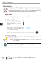
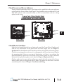
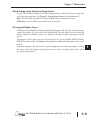
MAINTENANCE
CHAPTER
7
In This Chapter...
Project Backup . . . . . . . . . . . . . . . . . . . . . . . . . . . . . . . . . . . . . . . . . . . . . . . . . . . . . .7–2
Check Operating Environment . . . . . . . . . . . . . . . . . . . . . . . . . . . . . . . . . . . . . . . . .7–2
Check Operating Voltage . . . . . . . . . . . . . . . . . . . . . . . . . . . . . . . . . . . . . . . . . . . . .7–2
Check Transmit and Receive Indicators . . . . . . . . . . . . . . . . . . . . . . . . . . . . . . . . . .7–3
Check Physical Conditions . . . . . . . . . . . . . . . . . . . . . . . . . . . . . . . . . . . . . . . . . . . .7–3
Run Tests under the System Setup Screens . . . . . . . . . . . . . . . . . . . . . . . . . . . . . . .7–4
Check Settings under the System Setup Screens . . . . . . . . . . . . . . . . . . . . . . . . . .7–5
Cleaning the Display Screen . . . . . . . . . . . . . . . . . . . . . . . . . . . . . . . . . . . . . . . . . . .7–5
Check Project Functionality . . . . . . . . . . . . . . . . . . . . . . . . . . . . . . . . . . . . . . . . . . .7–6
Checks from the C-more Micro-Graphic Programming Software . . . . . . . . . . . . . .7–6
Chapter 7: Maintenance
1
2
3
4
5
6
7
8
9
10
11
12
13
14
A
B
C
D
Maintenance
7–2
Although the C-more® Micro-Graphic panels require very little maintenance, setting up a
routine maintenance schedule will ensure the longevity of the product in your application.
The following are some suggestions of items to include in a preventive maintenance list or
schedule. Most of these items should be scheduled quarterly or bi-annually.
Project Backup
During a routine preventive maintenance schedule is a good time to make sure that there is an
up-to-date backup of the application project.
Check Operating Environment
Make sure the C-more Micro-Graphic
panel is operating in the proper
temperature range: (0 to 50 °C (32 to
122 °F)).
Make sure the C-more Micro-Graphic panel is
operating within the specified humidity range:
(5–95% RH, non-condensing).
Make sure the operating environment is free of corrosive vapors and gasses.
CORROSIVE
8
Check Operating Voltage
Check the input voltage that is powering the C-more Micro-Graphic panel to make sure it is
within the appropriate range.
24 VDC: The acceptable voltage range to the panel is 10.2-26.4 VDC (6.5W @ 10.2
VDC (630mA)).
NOTE: When the panel is powered through Port1 from a connected PC, the screen brightness is diminished
because the panel is running in Low-Power Mode. Connect an external 12-24 VDC power source when the
panel is installed in its application for full brightness.
®
EA1-TCL-M Hardware User Manual, 2nd Ed. Rev. A, 07/13
Chapter 7: Maintenance
Check Transmit and Receive Indicators
During a routine maintenance check is a good time to take a quick look at the status indicators
on the back of the C-more Micro-Graphic panel. There should be activity on both the TxD and
RxD LED indicators when connected serially to a PLC or control device and data is being
updated on the screen.
C-more Color Micro-Graphic Panel
Communication Port Status Indicators
R**. 1 2 3 4 5
MODEL:EA1-T4CL
TxD Indicator
Port2
R
INPUT:12-24V 0.19-0.38A Class2
0.19-0.38A Class2
Date code:9048
MADE IN CHINA
7M17
IND.CONT.EQ.
EA1-T4CL+
EA1-T4CL
+094018001
RxD Indicator
Port2
R01. 1 2 3 4 5
MODEL:EA1-T6CL
R
INPUT:12-24V 6.5W
Date code:****
MADE IN CHINA
TxD Indicator
Port2
EA1-T4CL
LISTED
7M17
IND.CONT.EQ.
EA1-T6CL + serial number
8
1
15
9
RxD Indicator
Port2
EA1-T6CL
4
Check Physical Conditions
Make sure that harmful chemicals are not being used around the C-more Micro-Graphic panel.
Look for any deterioration of the panel’s bezel and front display area. See Chapter 2:
Specifications for identification of the materials on the face of the panels and accessory bezels.
Check the mounting gasket to make sure it is sealing properly and has not deteriorated. Replace
the mounting gasket if there are any signs of deterioration, or if there is any evidence that
moisture/liquids have penetrated to the inside of the enclosure where the panel is mounted.
Information on replacement gaskets can be found in Chapter 9: Replacement Parts.
Check to make sure that none of the cooling vents around the inside section of the C-more
Micro-Graphic panel are clogged with dust or debris. Also make sure that there is clearance
around the panel as shown in Chapter 4: Installation and Wiring.
®
EA1-TCL-M Hardware User Manual, 2nd Ed. Rev. A, 07/13
2 3
1
2
3
4
5
6
7
8
9
10
11
12
13
14
A
B
C
D
7–3
Chapter 7: Maintenance
Run Tests under the System Setup Screens
1
2
3
4
5
6
7
8
9
10
11
12
13
14
A
B
C
D
7–4
Use the C-more Micro-Graphic panel’s System Setup Screens to test communication port, PLC
connectivity, the internal beeper and touch screen operation. See Chapter 5: System Setup
Screens for additional details.
BAK
TEST MENU
1. Serial Port - Loop Back
2. PLC Enquiry Test
3. Buzzer Test
4. Touch Panel Test
5. Display Test
UP
DWN
ENT
ENT
Serial Port - Loop Back Test - Performs a test to verify either the RS-232 or the RS485/422
serial communications functionality from the 15-pin connector (Port 2) on the panel is
operating correctly. A loop back connector inserted into the port is required for proper testing.
Wiring diagrams to build RS-232 and RS-485/422 loop back connectors are shown below.
RS-232 Loop-back Connector
User Constructed
15-pin D-sub
(male)
2 TXD
15
3
RXD
7
CTS
8
RTS
1
Wiring Diagram
RS-422/485 Loop-back Connector
User Constructed
7 CTS 15-pin D-sub
(male)
8 RTS
9
RXD+
11
TXD+
10
RXD–
12
TXD–
15
1
Wiring Diagram
PLC Enquiry Test - Tests the communications with the selected PLC protocol between the
panel and a connected PLC.
Buzzer Test - Use this option to test the internal audible beeper of the panel.
Touch Panel Test - Tests the response of the touch screen area to contact. This test is used to
make sure the touch screen area is responding properly.
®
EA1-TCL-M Hardware User Manual, 2nd Ed. Rev. A, 07/13
Chapter 7: Maintenance
Check Settings under the System Setup Screens
Use the C-more Micro-Graphic panel’s System Setup Screens to check the various settings such
as the beep and orientation. See Chapter 5: System Setup Screens for additional details.
Beep - Used to enable or disable the internal audible beeper. the default is beep on.
Calibration - Used to calibrate the touch screen on the panel.
Cleaning the Display Screen
The display screen should be cleaned periodically by wiping it with a lint free damp cloth using
a mild soap solution. Dry the surface when finished with a lint free cloth. Do not use cleaning
solvents (ammonia, alcohol, acetone, etc.) which may damage the plastic housing and touch
screen.
The longevity of the touch screen can be increased by the use of the EA-4-COV2 or EA-6COV2 clear screen overlay. See Chapter 3: Accessories for additional information on the screen
overlay.
To prevent damage to the touch screen, avoid touching the screen with sharp objects, striking
the screen with a hard object, using abrasives on the screen, or using excessive force when
pressing the touch screen.
®
EA1-TCL-M Hardware User Manual, 2nd Ed. Rev. A, 07/13
1
2
3
4
5
6
7
8
9
10
11
12
13
14
A
B
C
D
7–5
Chapter 7: Maintenance
Check Project Functionality
1
2
3
4
5
6
7
8
9
10
11
12
13
14
A
B
C
D
7–6
During routine maintenance is a good time to check the functionality of your application,
making sure that various areas on different screens do what they were designed to do. An
outline or specification for the application is a useful tool for testing the various aspects of your
application. As a starting point, you may want to run through all the screens to make sure they
are accessible if the project allows this.
If there are any trouble-shooting procedures programmed into the C-more Micro-Graphic panel
application, now is a good time to also check these aids.
Checks from the C-more Micro-Graphic Programming Software
If you have a PC available with the C-more Micro-Graphic Programming Software,
EA-MG-PGMSW, installed, and the panel is connected to the PC, you can check the status of
the panel from the Panel Information window.
The Panel Information window shown below will indicate the panel type, if a keypad bezel has
been installed, the total memory, memory used, free memory, firmware version, mask ROM
version, and the PLC protocol selected for its serial communication ports. The programming
software can also be used to update the panel’s firmware to the latest version.
®
EA1-TCL-M Hardware User Manual, 2nd Ed. Rev. A, 07/13
Chapter 7: Maintenance
Notes:
_____________________________________________________________
_____________________________________________________________
_____________________________________________________________
_____________________________________________________________
_____________________________________________________________
_____________________________________________________________
_____________________________________________________________
_____________________________________________________________
_____________________________________________________________
_____________________________________________________________
_____________________________________________________________
_____________________________________________________________
_____________________________________________________________
_____________________________________________________________
_____________________________________________________________
_____________________________________________________________
_____________________________________________________________
_____________________________________________________________
_____________________________________________________________
_____________________________________________________________
_____________________________________________________________
_____________________________________________________________
_____________________________________________________________
_____________________________________________________________
_____________________________________________________________
_____________________________________________________________
_____________________________________________________________
_____________________________________________________________
_____________________________________________________________
_____________________________________________________________
_____________________________________________________________
_____________________________________________________________
_____________________________________________________________
®
EA1-TCL-M Hardware User Manual, 2nd Ed. Rev. A, 07/13
1
2
3
4
5
6
7
8
9
10
11
12
13
14
A
B
C
D
7–7